Table of Contents
Advertisement
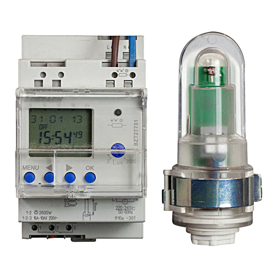
Tempus Lux
Digital Photoelectric Switch
BZT27731
Installation and
operating instructions
D GB CZ
PL HR
0
6
12
18
24
2
MENU
OK
1
2
0,5mm -
2
2,5mm
1-2
2600 W
1-2-3
16A-10AX
250V~
1
2
3
BZT27731
Correct connection required for smooth zero
crossing switch operation (see connection diagram)!
310380 01
2000
Lux
220-240V~
230-240V~
50-60Hz
R10a –30T
GB
Advertisement
Table of Contents

Related Manuals for Schrack Technik Tempus Lux BZT27731


Summary of Contents for Schrack Technik Tempus Lux BZT27731
- Page 1 310380 01 Tempus Lux Digital Photoelectric Switch BZT27731 Installation and operating instructions 2000 MENU D GB CZ 0,5mm - 2,5mm 230-240V~ 220-240V~ 50-60Hz 2600 W 1-2-3 16A-10AX 250V~ R10a –30T PL HR BZT27731 Correct connection required for smooth zero crossing switch operation (see connection diagram)!
-
Page 2: Table Of Contents
Contents Basic safety instructions Display and keys/operating instructions Overview of menu selection Connection/installation Connection/installation of light sensor Initial start-up Set lux values Menu item LIGHT Set delay Menu item PROGRAM Set switching time Menu item MANUAL Manual and permanent switching Menu item OPTIONS Enter PIN code Technical data... -
Page 3: Basic Safety Instructions
Basic advice WARNING Danger of death through electric shock or fire! Installation should only be carried out by a professional electrician! • The device is designed for installation on DIN top hat rails (in accordance with EN 60715) • Power reserve (10 years) Designated use •... -
Page 4: Display And Keys/Operating Instructions
Screen display and keys Operating instructions Programmed ON 1. Read text line switching times Flashing text/symbol represents query Date display Time display Channel status Days of the week from ON OFF 1 to 7 2. Make a decision Display of active keys with relevant function bbbb Confirmation... -
Page 5: Overview Of Menu Selection
Overview of menu selection MENU 19 10 08 LIGHT PROGRAM TIME/DATE MANUAL OPTIONS 9:40 ON DELAY TIME PERMANENT OPERATING FREE 56 HOURS METER DATE PERMANENT ON DELAY ILLUMINATION VIEW SUMMER-- MANUAL ON LANGUAGE WINTER CHANGE WEEKDAY TIMER... -
Page 6: Connection/Installation
Connection/installation WARNING Warning, danger of death through electric shock! Must be installed by a professional electrician! Disconnect power source! 45° cable Cover or shield any adjacent live components live components. Spring screwless Ensure device cannot be switched on! terminal ... -
Page 7: Connection/Installation Of Light Sensor
Connection/installation of light sensor Take length of connection cable into account max. 100 m 2 x 1,5 mm , max. 50 m 2 x 0,75 mm Avoid running sensor wiring wiring parallel to mains power cables. 0,5–2,5 mm , strip cable by 10 mm (max. -
Page 8: Initial Start-Up
Initial start-up GERMAN KEEP PROGRAM Set language, date, time as well DATE FORMAT as summer/ winter time YEAR MONTH P ress required key and display follows on screen (see fig). TIME FORMAT HOUR SUMMER- 28 02 08 MINUTE WINTER GB/ IRL/P ... -
Page 9: Set Lux Values
Set lux values The sun relay with external light sensor controls lighting equipment for streets, stairways, entrances etc. S et desired range from I-V with a screw tab a screw- driver on the potentiometer setting (see fig). ... -
Page 10: Set Delay
Set delay An on/off delay of 1 minute is preset to avoid faulty operation caused by lightning, car headlights etc. LIGHT ON DELAY When the delay ends the channel status will ON DELAY flash ON/OFF. MINUTE MINUTE SECONDS SECONDS ... -
Page 11: Set Switching Time
Set switching time (e.g. with a night switch off at the weekend 23:00–05:00) PROGRAM Press MENU (see fig.). NIGHTSWITCH VIEW HOUR CHANGE There are 56 available memory MINUTE cells. DELETE MONDAY LASTS Switching time UNTIL for one day same switching time for ... -
Page 12: Manual And Permanent Switching
Manual and permanent switching Manual control Manual and permanent switching can be set Reversing the channel status to the next auto- using the menu in MANUAL or (in the auto- matic or programmed switching. matic screen) by key combination (see fig). Permanent switching Channel As long as a permanent switching (on or off) -
Page 13: Enter Pin Code
Enter PIN code The PIN-Code is set via the menu in OPTIONS (see picture). If you have forgotten the PIN please call the Hotline. OPTIONS OPERATING HOURS METER ILLUMINATION LANGUAGE WITHOUT PIN WITH PIN FACTORY SETTINGS CURRENT INFO NEW PIN ... -
Page 14: Technical Data
10 A/250 V~ cos ϕ = 0,6 Service address/Hotline Fluorescent lamps: 10 AX Switching capacity min.: 10 mA/230 V AC 100 mA/12 V AC/DC Schrack Technik GmbH Glow lamp load: 2600 W www.schrack.com Halogen lamp load: 2600 W Fluorescent lamps (VVG – low-loss series devices):...
Need help?
Do you have a question about the Tempus Lux BZT27731 and is the answer not in the manual?
Questions and answers