Table of Contents
Advertisement
Advertisement
Table of Contents

Related Manuals for Samsung 400T8A


Summary of Contents for Samsung 400T8A
- Page 1 400T8A/400S8A User Manual...
-
Page 2: Table Of Contents
Connecting an External Display Device Chapter 6. Appendix Connecting Speakers Adjusting the Volume Important Safety Information Wired LAN Replacement Parts and Accessories Wireless LAN Regulatory Compliance Statements Samsung Update WEEE Symbol Information Online Support (S Service) Samsung Packaging Take-Back Program Product Specifications Glossary... - Page 3 Chapter 1. Getting Started Before You Start Safety Precautions Ergonomic tips Package Contents Overview Installing the Computer Turning the Computer On and Off...
-
Page 4: Before You Start
Before You Start Chapter 1. Getting Started Before reading the User Manual, first check the following Safety Precaution Notations information. • Optional items, some devices and software referred to in Icon Notation Description the User Manual may not be provided and/or changed by upgrade. - Page 5 Samsung Electronics shall not be liable for any data loss. Please take care to avoid losing any important data and backup your data to prevent any such data loss.
- Page 6 Before You Start Chapter 1. Getting Started About Memory Capacity Representation About the Product Capacity Representation Standard The memory capacity reported in Windows is less than the actual capacity of memory. About the capacity representation of the storage This is because BIOS or a video adapter uses a portion of memory or claims it for further use.
-
Page 7: Safety Precautions
• Do not touch with wet hands. • Do not use a damaged power cord. • Since this is commonly applied to Samsung Computers, • Do not overload a multi-outlet or an extension cord beyond some pictures may differ from actual products. - Page 8 Failure to do so may result in electric shock or fire due to the • Samsung cannot be responsible for the user’s safety when malfunction of the inner part. using accessories or supplies that are not approved by Samsung.
- Page 9 If the computer is dropped or broken, disconnect the power cord A blocked vent causes the computer to overheat, resulting in an and contact a Samsung Service Center. explosion, fire, burns, or computer malfunction. Using a broken computer may result in electric shock or fire.
- Page 10 Safety Precautions Chapter 1. Getting Started Do not place heavy objects on the product. Caution This may cause a problem with the computer. In addition, the object may fall and cause injury or damage the computer. Failure to follow instructions marked with this symbol may result in minor physical injury or damage to the computer.
- Page 11 Failure to do so may result in damage to the product. Broken glass or acrylic could cause injury to your hands and face. Take the device to a Samsung Service Center to have it repaired. If the product emits smoke or there is a burning smell, disconnect the power plug from the wall outlet and contact a When using wireless communication (LAN, Bluetooth, etc.)
- Page 12 The airport security devices that check Do not attempt to upgrade the computer, unless you are carry-on luggage, such as conveyor belts, use X-rays instead of qualified. Otherwise, contact a Samsung Service Center or an magnetism and will not damage a drive. authorized technician.
- Page 13 • The data may be lost and irrecoverable due to a computer virus. • The data may be lost if the power is turned off while running an application. • Samsung is not liable for any loss of data on the storage device.
-
Page 14: Ergonomic Tips
Ergonomic tips Chapter 1. Getting Started Maintaining the proper posture during computer use is very • Use an adjustable chair with firm, comfortable support. important to prevent physical injury. Improper or prolonged • Adjust the height of your chair so that thighs are horizontal to keyboard use may result in repetitive strain injury. - Page 15 Ergonomic tips Chapter 1. Getting Started Arms and hands • When using the keyboard and touchpad, the shoulders should be relaxed. The upper arm and forearm should form an angle that is slightly greater than a right angle, with the wrist and hand in almost a straight line.
- Page 16 Ergonomic tips Chapter 1. Getting Started Eye position and display illumination Hearing and volume control VOLUME Check your volume! • Ensure that the volume is not too loud before using the headset or earpiece. Excessive exposure to loud sounds can • Position the screen at least 50 cm away from your eyes.
- Page 17 Ergonomic tips Chapter 1. Getting Started Operating conditions Use caution when exposed to flashing lights. • While using your computer, leave some lights on in the room • Take at least a 10 minute break every hour. and do not hold the screen too close to your eyes. • Avoid using the computer in dark locations.
-
Page 18: Package Contents
Package Contents Chapter 1. Getting Started Contents of 400T8A Keyboard Mouse Computer Power Cord • The appearance and color of the keyboard and mouse may differ depending on your computer model. • The appearance of the power cord may differ from country to country. - Page 19 Package Contents Chapter 1. Getting Started Contents of 400S8A Keyboard Mouse Computer Power Cord • The appearance and color of the keyboard and mouse may differ depending on your computer model. • The appearance of the power cord may differ from country to country. • The appearance and package contents of the computer may differ depending on your computer model.
-
Page 20: Overview
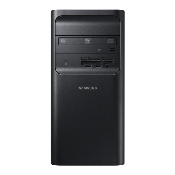
Overview Chapter 1. Getting Started Front View of 400T8A CD Drive (ODD, Optional) or Memory Card Slot (Optional) CD Drive expansion space (Optional) A card slot supports memory cards. CD Drive (ODD, Optional) This drive allows you to read CDs or DVDs. - Page 21 Overview Chapter 1. Getting Started Rear View of 400T8A PS/2 Port (for PS/2-compatible keyboards or mouse devices) AC-IN Port You can connect a PS / 2 type Keyboard/Mouse here. You can connect the power cord here. Printer Port (Optional) Internal Graphics Port (Optional) You can connect a parallel device such as a printer here.
- Page 22 Overview Chapter 1. Getting Started Front View of 400S8A CD Drive (ODD, Optional) This drive allows you to read CDs or DVDs. Memory Card Slot (Optional) A card slot supports memory cards. Power button and status light Turns the computer on/off and indicates Earpiece/Headset Jack the operating status of the computer via the border color.
- Page 23 Overview Chapter 1. Getting Started Rear View of 400S8A PS/2 Port (for PS/2-compatible keyboards or mouse devices) Internal Graphics Port (Optional) You can connect a PS / 2 type Keyboard/Mouse here. DVI Port (Supports DVI-I or DVI-D) Printer Port (Optional) RGB Port ...
-
Page 24: Installing The Computer
Connect the keyboard and the mouse to corresponding ports. The keyboard and the mouse may vary depending on the model. When the mouse supporting USB 2.0 is connected to the USB 3.0 port, it operates with the USB 2.0 speed. • 400T8A • 400S8A USB Port... - Page 25 Installing the Computer Chapter 1. Getting Started Connecting the Monitor/TV When Using the Internal Graphics Card (Optional) Connect to the RGB Port or HDMI Port. • 400T8A • 400S8A DVI Port DVI Port RGB Port RGB Port HDMI Port HDMI Port...
- Page 26 Installing the Computer Chapter 1. Getting Started When Using the External Graphics Card (Optional) Connect to the RGB Port, HDMI Port, or DVI Port. • 400S8A • 400T8A DVI Port HDMI Port DVI Port HDMI Port RGB Port Port • The location and type of the port may differ depending on the graphics card.
- Page 27 Installing the Computer Chapter 1. Getting Started Connecting the Speaker and the LAN Cable Connect the speaker and the LAN cable to corresponding ports. • 400T8A • 400S8A Connect the LAN cable Connect the LAN cable Connect the Speaker Connect the Speaker...
- Page 28 Installing the Computer Chapter 1. Getting Started Connecting the Power Cord Plug the power cord into the AC-IN port of the computer. • 400T8A • 400S8A AC-IN Port AC-IN Port...
-
Page 29: Turning The Computer On And Off
Reconnect the power cable and press the Power button. The computer will turn on. Power Button [400T8A] [400S8A] When you turn the computer on for the first time, the Windows activation screen appears. You must register your Windows information to use the computer. - Page 30 Turning the Computer On and Off Chapter 1. Getting Started Unlocking the screen Turning the computer off To unlock the lock screen, do one of the following: • Since the procedures to turn the computer off may differ • Mouse: Click the lock screen. depending on the installed operating system, please turn • Keyboard: Press any key.
-
Page 31: Chapter 2. Windows
Chapter 2. Windows Microsoft Windows Understanding the Screen... -
Page 32: Microsoft Windows
Microsoft Windows Chapter 2. Windows Microsoft Windows is an operating system that is used to control a Configuring the Windows Settings computer. You can configure the basic system settings, such as installing • Images and available features may differ depending on the or uninstalling apps and managing accounts, on the Windows model and operating system. -
Page 33: Understanding The Screen
Understanding the Screen Chapter 2. Windows Action Center • You can enable or disable push notifications for applications. You can also set personalized hot keys to The Windows 10 action center allows you to receive system appear in the action center by selecting the Start button notifications, such as updates, and push notifications, such as >... - Page 34 Chapter 3. Using the computer Keyboard Mouse CD Drive (ODD, Optional) Memory Card Slot (Optional) Connecting an External Display Device Connecting Speakers Adjusting the Volume Wired LAN Wireless LAN Samsung Update Online Support (S Service)
-
Page 35: Keyboard
Keyboard Chapter 3. Using the computer The appearance and color of the keyboard may differ with the model. Function keys Additional keys Indicators These operate various program You can delete/enter/edit text or These indicate whether functions. You can use them move the cursor up or down the page Num Lock, Caps Lock or differently depending on the... -
Page 36: Mouse
Mouse Chapter 3. Using the computer Click function A mouse is a user interface that enables users to move the cursor and pointer on the screen. Briefly press the left mouse button once. The appearance and color of the mouse may differ depending on If you click this mouse button once, the corresponding program is your computer model. - Page 37 Mouse Chapter 3. Using the computer Right click function Scroll Function If you right-click on the mouse once, the context-sensitive menu Turn the wheel upwards or downwards and the screen is scrolled of the current program appears. up or down accordingly. Drag function Dragging refers to clicking an item and moving the item to another position while holding the mouse button down.
-
Page 38: Cd Drive (Odd, Optional)
Push the CD tray to close it. A CD drive’s reading and writing speed may differ depending on the condition and type of the media. Inserting and Ejecting a CD (400T8A) Press the Eject button for the CD drive (ODD) to open the CD tray. - Page 39 CD Drive Chapter 3. (ODD, Optional) Using the computer When you press the Eject button again, the CD tray will close. Inserting and Ejecting a CD (400S8A) Press the Eject button for the optical disk drive to open the CD tray. Eject button Do not insert small discs such as 80 mm CDs into the computer when the computer is vertical.
-
Page 40: Memory Card Slot (Optional)
Memory Card Slot Chapter 3. (Optional) Using the computer Use a memory card as a removable storage device and transfer Abbreviation Description data to other digital devices, such as digital cameras. MS-Pro Memory Stick Pro Purchase a memory card with the necessary capacity for the MS-Pro Duo Memory Stick Pro Duo requirement. - Page 41 Memory Card Slot Chapter 3. (Optional) Using the computer Inserting a memory card For the 400S8A models, insert the memory card with the gold plated side facing to the right. If a dummy card or a memory card adapter is inserted in the If a pop-up message appears, select the pop-up message.
- Page 42 Memory Card Slot Chapter 3. (Optional) Using the computer Formatting a memory card • To use a memory card to exchange data with a digital device, such as a digital camera, formatting the data with Format the memory card to remove all data or before using it for the digital device is recommended.
-
Page 43: Connecting An External Display Device
• The location of the port may differ depending on the graphics card. When Using the External Graphics Card (Optional) [400T8A] [400S8A] ... - Page 44 Connecting an External Display Device Chapter 3. Using the computer About the connection cable Users should additionally purchase the necessary connection cables. • DVI Cable • HDMI Cable A cable used to connect A cable used to connect to a DVI port. to a HDMI port.
- Page 45 Connect an external display device to the DVI, HDMI, RGB port Audio OUT port of the computer via an audio cable (sold and select External IN on the external display device. separately). • [400T8A] L-AUDIO-R VIDEO HDMI • If the Desktop screen does not fit the external display, you can set it in the graphics card’s Control Panel.
- Page 46 Connecting an External Display Device Chapter 3. Using the computer Setting up HDMI external display audio Setting up the screen when two devices are connected You can configure the sound of the computer to be played through the HDMI external display. Connect the power cable to the connected monitor, TV, or projector, and turn on the power.
-
Page 47: Connecting Speakers
You can connect 5.1 channel analog speakers to the ports at the back. ► Front Earpiece/Headset Ports Since the speaker ports at the back are for amplifying a speaker system, the output of these ports may differ from the ports at the front. [400T8A] [400S8A] Connect the earpiece/headset Connect the earpiece/headset ►... - Page 48 Connecting Speakers Chapter 3. Using the computer icon, select the Rear speaker output Double-click the Connecting Analog Speakers item of the Back Pannel and click OK. You can connect up to 6 speakers to the audio jacks on the rear panel of the computer for 5.1 channel sound.
-
Page 49: Adjusting The Volume
Adjusting the Volume Chapter 3. Using the computer You can adjust the volume using the taskbar. Using the Voice Recorder When speakers or headphones are connected to the computer, will appear on the taskbar. You can record to the computer using the Windows recording program. -
Page 50: Wired Lan
Wired LAN Chapter 3. Using the computer > Network & Internet > To access the Internet at home, set up an account with an Internet Select the Start button ( ) > Ethernet > Change adapter options. service provider (ISP). To purchase Internet service and a modem, contact a local ISP. - Page 51 Wired LAN Chapter 3. Using the computer Select Internet Protocol Version 4 (TCP/IPv4) from the Configure the IP settings. list below This connection uses the following items > • When using DHCP, select Obtain an IP address Properties. automatically. • The Network Component name may differ depending on • When not using DHCP, contact the network administrator for the operating system.
- Page 52 Wired LAN Chapter 3. Using the computer Right-click Ethernet and select Properties. Wake on LAN (WOL) feature You can activate the system remotely from sleep mode using Select Configure… > Power Management > Allow this Wake on LAN. device to wake the computer > OK. <Wake on LAN>...
-
Page 53: Wireless Lan
Wireless LAN Chapter 3. Using the computer Connect the computer to a wireless network to use the Internet. Select a network from the list of detected wireless networks and select Connect automatically > Connect. The descriptions below are for computer models with a Wireless LAN card or device. -
Page 54: Samsung Update
Samsung Update Chapter 3. Using the computer Use Samsung Update to install and update Samsung applications Select Update all. Or, select Install or Update of the item to and drivers on the computer easily and conveniently. This be updated. application enables the user to search for or download the BIOS, The items will be updated. -
Page 55: Online Support (S Service)
A service associate can resolve any problems you have with your computer using the online chat and remote control program. You Enter the Contents and select Request. can receive the help when you are having trouble using Samsung software. Online Support (S Service) You can access the online service for free for a certain period of time after purchasing your computer. - Page 56 Chapter 4. Settings and Upgrade BIOS Setup Setting a Boot Password Changing the Boot Priority Disassembling the computer Interior computer components Main board structure Adding cards Adding memory Adding the hard drive (HDD) Exchanging the CD drive (ODD) Exchanging the CPU Exchanging the CMOS battery...
-
Page 57: Bios Setup
BIOS Setup Chapter 4. Settings and Upgrade The BIOS Setup enables you to configure your computer hardware Entering the BIOS Setup according to your needs. Turn the computer on. • Use the BIOS setup to define a boot password, change the booting priority, or add a new device. - Page 58 BIOS Setup Chapter 4. Settings and Upgrade The BIOS Setup Screen Setup Menu Description This is a description about the basic SysInfo specifications of the computer. The BIOS Setup menus and items may differ depending on your computer model. Using this menu, you can configure the major Advanced chipsets and additional functions.
- Page 59 BIOS Setup Chapter 4. Settings and Upgrade System Setup Keys The keyboard image may differ from the actual keyboard. In the Setup, you have to use the keyboard. Press to view the Setup Help. Up & Down Press to move up and down. Keys F5/F6 Press to change the item value.
-
Page 60: Setting A Boot Password
Setting a Boot Password Chapter 4. Settings and Upgrade If you set a password, you have to enter the password when you Setting a Supervisor Password turn the computer on or enter the BIOS Setup. If you set a Supervisor Password, you need to enter the password By configuring a password, you can restrict system access to when you turn the computer on or enter the BIOS Setup. - Page 61 Setting a Boot Password Chapter 4. Settings and Upgrade Enter a password, press <Enter>, re-enter the password for Setting a User Password confirmation, and press <Enter> again. Using the User Password, you can turn the computer on but you The password can be up to 20 alphanumeric characters. cannot change the major settings of the BIOS Setup because you Special characters are not allowed.
- Page 62 Setting a Boot Password Chapter 4. Settings and Upgrade Setting up a Hard Disk Drive Password (Optional) Deactivating the Password If you set a password for a hard disk drive, it cannot be accessed Press <Enter> on the password to be deactivated. For from another computer.
- Page 63 Setting a Boot Password Chapter 4. Settings and Upgrade Press the latch holding in the CMOS battery and remove the If you have forgotten an administrator or user battery, then reinsert after 1-2 minutes. password You can cancel the password using the computer main board’s CMOS battery.
-
Page 64: Changing The Boot Priority
Changing the Boot Priority Chapter 4. Settings and Upgrade Press <Enter> on the Boot Option #1 item. Changing the Boot Priority Select the drive to boot from. Select the Boot menu in the BIOS Setup. Press <Enter> on the Boot Device Priority item. BIOS Setup SysInfo Advanced... -
Page 65: Disassembling The Computer
Disassembling the computer Chapter 4. (for 400T8A models only) Settings and Upgrade You must open the cover to replace or add computer parts. The Opening the computer cover computer's form and interior structure may differ depending on selected specifications. Lie the computer on its side and use a screwdriver to remove If you are not comfortable doing the expansion yourself, please the 2 screws from its back. - Page 66 Disassembling the computer Chapter 4. (for 400T8A models only) Settings and Upgrade Lift the cover in the direction of the arrow. Turn the screws in the back of the computer to the right to tighten. To close the cover again, place the cover on the triangle ( ) on the computer and then push it forward to the end of the front cover.
- Page 67 Disassembling the computer Chapter 4. (for 400T8A models only) Settings and Upgrade Pull the bottom two latches upward and push the top two Removing the front cover latches to the center to remove the front cover. You must remove the front cover to exchange the CD drive.
- Page 68 Disassembling the computer Chapter 4. (for 400S8A models only) Settings and Upgrade You must open the cover to replace or add computer parts. The Opening the computer cover computer’s form and interior structure may differ depending on selected specifications. Lie the computer on its side and use a screwdriver to remove If you are not comfortable doing the expansion yourself, please the 2 screws from its back.
- Page 69 Disassembling the computer Chapter 4. (for 400S8A models only) Settings and Upgrade Lift the cover in the direction of the arrow. Turn the screws in the back of the computer to the right to tighten. To close the cover again, place the cover on the triangle ( ) on the computer and then push it forward to the end of the front cover.
-
Page 70: Interior Computer Components
Interior computer components Chapter 4. Settings and Upgrade • The computer's interior structure may differ depending on the model and selected specifications. • The installed cooling fan may differ by model. [400T8A] [400S8A] CD drive or CD drive CD drive... -
Page 71: Main Board Structure
Main board structure Chapter 4. Settings and Upgrade Cooling fan power connector Auxiliary power connector CMOS battery Memory socket Cooling fan / Heat sink / CPU (central processing unit) SSD (selected specifications) Main power connector SSD slot Front power / LED connector PCI Express X16 card slot Wireless LAN card slot PCI Express X1 card slot... -
Page 72: Adding Cards
Adding cards Chapter 4. (for 400T8A models only) Settings and Upgrade Check that there are slots which can be used for expansion and Open the computer cover. then check that the card you want to install is compatible with your computer. - Page 73 Adding cards Chapter 4. (for 400T8A models only) Settings and Upgrade Fix the card in place with the screws you removed. Connect the necessary internal cables according to the manual for the card you purchased. Close the cover and connect external cables, including the power cable.
- Page 74 Adding cards Chapter 4. (for 400S8A models only) Settings and Upgrade Check that there are slots which can be used for expansion and Open the computer cover. then check that the card you want to install is compatible with your computer. Remove the screw holding the bracket.
- Page 75 Adding cards Chapter 4. (for 400S8A models only) Settings and Upgrade Fix the card in place with the screws you removed. Connect the necessary internal cables according to the manual for the card you purchased. Close the cover and connect external cables, including the power cable.
-
Page 76: Adding Memory
Adding memory Chapter 4. Settings and Upgrade Check that there is a memory socket to be used for expansion on Insert the memory in the direction of the socket and slot and the main board and then prepare memory that can be used in push until it is completely installed. -
Page 77: Adding The Hard Drive (Hdd)
Adding the hard drive (HDD) Chapter 4. (for 400T8A models only) Settings and Upgrade Remove power cables or signal cables connecting the current Parallel (IDE) hard drive connections are not available on this hard drive. computer’s main board, so you cannot use parallel (IDE) hard drives with it. - Page 78 Adding the hard drive (HDD) Chapter 4. (for 400T8A models only) Settings and Upgrade Insert the new hard drive and secure it with four screws. Connect the other end of the new hard drive’s signal cable to the main board’s SATA 2 port.
- Page 79 Adding the hard drive (HDD) Chapter 4. (for 400S8A models only) Settings and Upgrade Pull and lift the CD bracket as in the picture to tilt it upward. Parallel (IDE) hard drive connections are not available on this computer's main board, so you cannot use parallel (IDE) hard drives with it.
- Page 80 Adding the hard drive (HDD) Chapter 4. (for 400S8A models only) Settings and Upgrade Remove power cables or signal cables connecting the current Connect the power cable and signal cable to the hard drive hard drive. and then install the hard drive case in the computer. Connect this to the new hard drive.
- Page 81 Adding the hard drive (HDD) Chapter 4. (for 400S8A models only) Settings and Upgrade Connect the other end of the new hard drive’s signal cable to Fix the hard drive case in place with the screw. the main board’s SATA 2 port. Close the computer cover and refer to the manual for the The hard drive supporting SATA 3.0 should be connected to hard drive you purchased to set it up as necessary.
-
Page 82: Exchanging The Cd Drive (Odd)
Exchanging the CD drive (ODD) Chapter 4. (for 400T8A models only) Settings and Upgrade The computer can be replaced with the series (SATA) type drive. Remove the CD drive screws and replace the CD drive with a new CD drive. - Page 83 Exchanging the CD drive (ODD) Chapter 4. (for 400T8A models only) Settings and Upgrade Connect the power and the signal cables to the new CD drive. Power cable Signal cable The picture above displays a computer without the CD drive bracket, and should be used as a reference only.
- Page 84 Exchanging the CD drive (ODD) Chapter 4. (for 400S8A models only) Settings and Upgrade Gently push the CD drive bracket inward and then lift • Only CD drives of the correct type for this model can be upward to remove. ...
- Page 85 Exchanging the CD drive (ODD) Chapter 4. (for 400S8A models only) Settings and Upgrade Remove the 4 screws holding the lower bracket and then Connect the power/signal cables to the CD drive and remove the CD drive. Put in the new CD drive. reassemble the CD drive bracket in the opposite order as you disassembled it, then screw in the 2 screws.
-
Page 86: Exchanging The Cpu
Exchanging the CPU Chapter 4. Settings and Upgrade Remove the 4 screws holding the cooling fan and then take • If you are not comfortable doing the replacement yourself, out the cooling fan. please contact a service center for support. However, there is a cost for services related to expansion even during the free service period. - Page 87 Exchanging the CPU Chapter 4. Settings and Upgrade Push the CPU lever out slightly to remove and then tilt Lower the bracket and then push the CPU lever downward the bracket upward and take out the CPU. until it locks in place. ...
-
Page 88: Exchanging The Cmos Battery
Because the CMOS battery is an expendable part, it may need Turn on the computer. When the Samsung logo appears, to be exchanged for a new battery if a "CMOS Checksum error" press the F2 key to enter BIOS setup and change the settings message appears while the computer is on. -
Page 89: Chapter 5. Backup / Restore
Chapter 5. Backup / Restore Samsung Recovery Windows reinstallation (Optional) Q&A... -
Page 90: Samsung Recovery
See "Backing up data". the computer. When the computer starts Windows: Select the Start button ( ) > Samsung Recovery. • The Samsung Recovery application may not be provided in models with less than 64 GB of storage. If you cannot... - Page 91 Backing up the current system You can back up the factory default system or current system to an alternate internal drive or an external storage device. Select the Start button ( ) > Samsung Recovery > Back up computer.
- Page 92 When backing up to an external storage device, connect the device to the computer. Backing up user data Select the Start button ( ) > Samsung Recovery. You can back up data files and folders. Select Backup and restore management.
- Page 93 Connect the new drive to the computer with an external hard drive connector. Select the Start button ( ) > Samsung Recovery. Select Create a factory state disk or Create a disk copy.
- Page 94 Samsung Recovery Chapter 5. Backup / Restore Windows recovery function If the Samsung Recovery application is not supported by the computer, reinstall Windows using the recovery function of Windows. Reinstalling Windows will erase all data saved on the computer. Back up application and personal data to an external storage device before reinstalling Windows.
-
Page 95: Windows Reinstallation (Optional)
• The data (files, programs) in the hard disk may be deleted if you reinstall Windows. This screen may not appear depending on the OS version. • Be sure to back up any important data. Samsung is not responsible for the loss of data. - Page 96 If you click Designating user, installation starts from Step 5. The D drive saves the images backed up by Samsung If you click Upgrade, installation starts from Step 6. Recovery solution. Install Windows on the C drive.
- Page 97 When the window appears asking where Windows is installed, select the disk partition you want and click Next. The D drive saves the images backed up by Samsung Recovery solution. Install Windows on the C drive. • If you click Drive options (advanced), you can delete, The option window for language, time, and keyboard settings format, create, or expand the partitions.
- Page 98 The computer has an additional partition for restoring data or the capacity representation of the HDD in Windows is smaller than saving backup files (only for models with the Samsung Recovery the actual capacity. The capacity representation in Windows may application).
- Page 99 How can I restore a computer that does not have the On the list, select an app to delete, and then select Uninstall. Samsung Recovery application? Restore the computer with the recovery function provided by Windows. Refer to the Recover Functionality item in the help for...
- Page 100 Chapter 6. Appendix Important Safety Information Replacement Parts and Accessories Regulatory Compliance Statements WEEE Symbol Information Samsung Packaging Take-Back Program Product Specifications Glossary...
-
Page 101: Important Safety Information
Important Safety Information Chapter 6. Appendix • If your computer has a voltage selector switch, make sure that Safety Instructions the switch is in the proper position for your area. Your system is designed and tested to meet the latest standards • Openings in the computer case are provided for ventilation. - Page 102 Important Safety Information Chapter 6. Appendix Care During Use Operating instructions • Do not walk on the power cord or allow anything to rest on it. 1. When installing and operating devices please refer to safety requirements in the user manual. • Do not spill anything on the system.
-
Page 103: Replacement Parts And Accessories
CD or DVD drive. Contact the Samsung Helpline for information on how to dispose • Class 1M laser radiation when operating part is open. of batteries that you cannot use or recharge any longer. - Page 104 Replacement Parts and Accessories Chapter 6. Appendix General Requirements Connecting and disconnecting the AC adapter The requirements listed below are applicable to all countries: The socket-outlet shall be installed near the equipment and shall be easily accessible. • All power cord sets must be approved by an acceptable Do not unplug the power cord by pulling the cable only.
-
Page 105: Regulatory Compliance Statements
Regulatory Compliance Statements Chapter 6. Appendix Wireless Guidance • Radio frequency wireless communication can interfere with equipment on commercial aircraft. Current aviation (If fitted with 2.4G band or 5G band) regulations require wireless devices to be turned off while traveling in an airplane. Low power, Radio LAN type devices (radio frequency (RF) wireless 802.11ABGN (also known as wireless Ethernet or Wi-Fi) and communication devices), operating in the 2.4GHz/5GHz Band, may... - Page 106 Regulatory Compliance Statements Chapter 6. Appendix United States of America • Wireless devices are not user serviceable. Do not modify them in any way. Modification to a wireless device will void the authorization to use it. Please contact manufacturer for USA and Canada Safety Requirements and Notices service.
- Page 107 Responsible Party – U.S. Contact Information • Increase the separation between the equipment and receiver. Samsung Electronics America, Inc. • Connect the equipment into an outlet on a circuit different QA Lab America from that to which the receiver is connected.
- Page 108 Regulatory Compliance Statements Chapter 6. Appendix If necessary, the user should consult the dealer or an experienced This device is restricted to indoor use due to its operation in the radio/television technician for additional suggestions. The user 5.15 to 5.25 GHz frequency range. FCC requires this product to be may find the following booklet helpful: “Something About used indoors for the frequency range 5.15 to 5.25 GHz to reduce Interference.”...
- Page 109 For body worn operation, this model meets the FCC RF exposure at multiple power levels so as to use only the power required to guidelines when used with Samsung accessory designated for this reach the network. In general, the closer you are to a wireless base product.
- Page 110 Samsung Electronics Suzhou Computer Co., Ltd. No. 198, Fangzhou Road, Suzhou Industrial Park, Jiangsu Province, 215021, China Tel: +86-0512-6253-8988 For the web or the phone number of the Samsung Service Center, see the Warranty or contact the retailer where you purchased your product.
-
Page 111: Weee Symbol Information
To find the nearest recycling location, go to our website: www.samsung.com/recyclingdirect or call, (877) 278-0799 For more information on safe disposal and recycling visit our For battery recycling go to call2recycle.org; or call 1-800-822-8837 website www.samsung.com/in or contact our Helpline numbers - 18002668282, 180030008282. This product is RoHS compliant. -
Page 112: Samsung Packaging Take-Back Program
Samsung Packaging Take-Back Program Chapter 6. Appendix In partnering with select recyclers, Samsung offers packaging take-back at no cost to you. Simply call the following number for the locations nearest you. CRT Processing, LLC (877) 278-0799 Kathy Severson – Logistics contact Dispose unwanted electronics through an approved recycler. -
Page 113: Product Specifications
• The amount of memory that Windows can use may be smaller than the actual amount of memory available. Input voltage AC200-240 V (for 220) or AC100-240 V 400T8A: 4.5 A, 6.0 A or 6.5 A Input current 400S8A: 4.0 A or 4.5 A Output voltage... - Page 114 Product Specifications Chapter 6. Appendix Trademarks • Samsung and the Samsung logo are trademarks or registered trademarks of Samsung Electronics. • Intel, Pentium®, and Core™ are trademarks or registered trademarks of the Intel Corporation. • Microsoft, MS-DOS, Vista, XP, and Windows are trademarks or registered trademarks of the Microsoft Corporation.
-
Page 115: Glossary
Glossary Chapter 6. Appendix The Glossary lists the terminologies used in this User Manual. For terminologies other than these, look in Windows Help. Backup DHCP (Dynamic Host Configuration Protocol) A way to save the current data to restore it later if necessary. This refers to automatically allocating IP addresses to the users on A backup is a way to restore computer data when the data or the network by the network administrators. - Page 116 Glossary Chapter 6. Appendix DVD (Digital Versatile Disk) LAN (Local Area Network) DVD was developed to replace CD (compact disk). Although the A communications network connecting computers, printers and shape and size of the disc are the same as that of a CD, the capacity other devices within a local area such as within a building.
- Page 117 Glossary Chapter 6. Appendix Network SDHC (Secure Digital High Capacity) card A group of computers and devices, such as printers and scanners, This is the extension of the SD card that supports over 2GB bytes. connected by a communications link. A network can be either SDXC (Secure Digital eXtended Capacity) small or large and can be connected permanently through cables SDXC provides a higher capacity and speed than the SDHC...
- Page 118 Glossary Chapter 6. Appendix System File Windows Media Player System Files refer to files that are read and used by the Windows A multimedia program included with Windows. Using this operating system. In general, system files must not be deleted or program, you can play a media file, create an audio CD, listen to a moved.
Need help?
Do you have a question about the 400T8A and is the answer not in the manual?
Questions and answers