Advertisement
Quick Links
3
Instructions
For the Assembly of the 68, 80, 100 Position MDR
103XX-12R1-00 and 103XX-12S1-00 Metal Junction
Shells for Pleated Foil Cable and 101XX-6000 Series
MDR Plug.
General:
The 103XX-12R1-00 MDR Junction Shells provide
grounding, EMI/RFI shielding, thumb screw retention, and
strain relief .
Kit Contents:
4 each M2.5 flat head thread
cutting screws
2 each Metal shell halves
2 each Thumb screws
2 each Elastomer gaskets
2 each Metal strain reliefs
NOTE: Kit 103XX-12S1 does
not include the elastomer
gasket material. Contact 3M for details.
Tools Needed:
• 3430-7000 Hand Tool (Scribe)
• Straight edge (Metal ruler)
• Philips screwdriver (No. 1 point head)
• 4000-2000 Cable Splitter
• 3640 or 3335 Assembly Press
NOTE: Because of the torque/pressure involved with
using the thread cutting screws, make sure the
recommended No. 1 pt. Philips screwdriver is used.
Cable Preparation
The cable, shield, and jacket should be trimmed to the
recommended dimensions shown in Figure 2.
Figure 2
• 3/4" cable should be exposed.
• 1/4" pleated foil should be exposed.
• 1/2" cable jacket should be trimmed along the side.
After terminating the connector to the cable, the assembly is
ready to be installed in the junction shell.
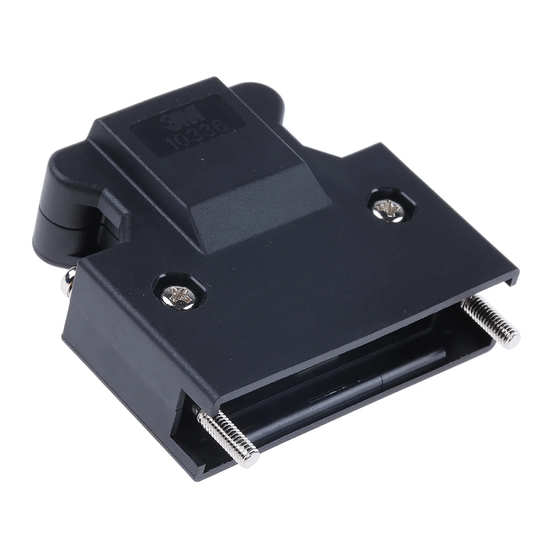
Figure 1
1-1/2"
1/2"
1/4"
3/4"
Assembly
1. Place the top half of the junction shell next to the bottom
half, with the inside of each half facing up. See Figure 3.
Figure 3
• The top half of the shell has four holes on the side with
the 3M logo.
• The bottom half of the shell has no holes on the side with
the 3M logo. See Figure 4.
Bottom Half
Figure 4
2. Insert the Elastomer Gasket in both halves as shown in
Figure 5. (Gasket material in vertical position.)
3. Insert the metal strain reliefs, with flat side facing up as
shown in Figure 5.
Figure 5
Top Half
Advertisement

Related Manuals for 3M 103 12R1-00 Series


Summary of Contents for 3M 103 12R1-00 Series
- Page 1 3M logo. Figure 1 not include the elastomer • The bottom half of the shell has no holes on the side with gasket material. Contact 3M for details. the 3M logo. See Figure 4. Tools Needed: • 3430-7000 Hand Tool (Scribe) •...
- Page 2 Elastomer Gasket. Figure 13 Figure 8 For technical, sales, or ordering information, contact 3M at: To receive this technical document via fax on demand, call Phone: 1-800-225-5373 the 3M Automated Information Response System at...