
Related Manuals for Doran 1200 Series


Summary of Contents for Doran 1200 Series
- Page 1 1200 Series Digital Indicator Technical Manual MAN350 – Rev 2 Doran Scales, Inc. www.doranscales.com...
-
Page 2: Table Of Contents
Table of Contents Introduction .......................... 1 Unpacking Your Scale ........................1 Specifications ..........................2 Scale Function ..........................3 Battery Operation ......................... 7 Power Off ............................7 Low Battery ...........................7 Recharging Battery.........................7 Load Cell Connection ......................8 Load Cell Connector Pinout ......................8 Scale Setup Guide ........................9 Entering Setup Mode ........................9 Setup Mode Navigation ........................9 Data Communications ...................... -
Page 3: Introduction
Introduction Thank you for purchasing a Doran Scales product. Please read this manual to ensure obtaining all the benefits that this indicator can provide. If any questions arise, please contact the Doran Scales Technical Support Department at 630-879-1288. Unpacking Your Scale Before unpacking your Doran scale, please read the instructions in this section. -
Page 4: Specifications
Specifications Class III – 10,000d; Cert. 19-013 NTEP Certificate Enclosure ABS Plastic 9” W x 7.5” H x 2.75” D (includes u-bracket) Product Dimensions Environmental Protection IP5X Legal for Trade 14 F to 104F (-10 C to +40 C) Temperature Range Capacity Range 1 to 999,000 lb Resolution Range... -
Page 5: Scale Function
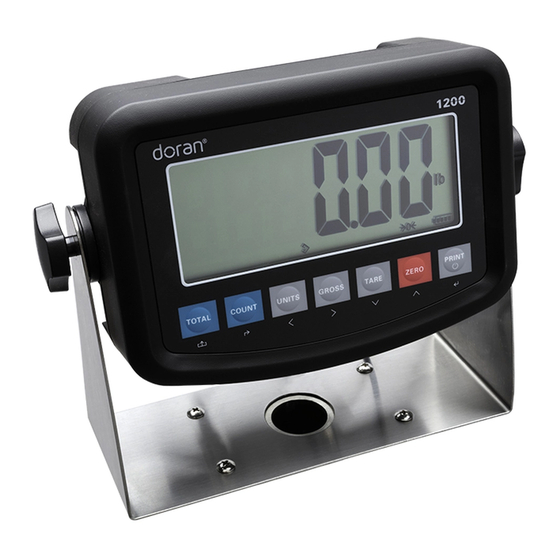
Fig. 1: Front Panel Scale Function Motion indicator. This symbol represents motion or instability of the weight. The annunciator will illuminate when motion is sensed on the platform. Changes in weight, vibration or air currents can cause the scale to go into motion. Center of zero indicator. - Page 6 Under, Accept and Over in checkweigh mode. F1.10 parameter controls the current function. Checkweighing is the default function. Indicates the count function is active Indicates the accumulation function is active Battery indicator Power Up Connect the cord to a compatible power source. Briefly press PRINT (On/Off) until the scale beeps.
- Page 7 TOTAL (Accumulator) The TOTAL annunciator is lit when the accumulation function is active. The accumulator will track the number of weights and total amount of weight on the scale. Do not change units during an accumulation process. Accumulate 1. Place item on the scale 2.
- Page 8 Set piece weight with manual weight entry (F2.4 = 1) 1. Place the container on the scale 2. Press ZERO 3. Place the piece sample into the container 4. Press and hold COUNT until SANPLE is displayed 5. Press PRINT 6.
-
Page 9: Battery Operation
Battery Operation The indicator will run continuously for up to 38 hours with four 350 ohm load cells. To maximize battery life, set the Automatic Shutoff Timer (F3.5) which will automatically powers down the scale after a period of non-use. Power Off 1) Manual - Press and hold the PRINT push button until the display turns off. -
Page 10: Load Cell Connection
Load Cell Connection Load Cell Connector Pinout Description + SIG + Signal - SIG - Signal + EX + Excitation - EX - Excitation Ground... -
Page 11: Scale Setup Guide
Scale Setup Guide Entering Setup Mode The calibration push button is located behind a door on the rear of the indicator. Remove the screw and press and hold the button down until the scale beeps. Setup will be displayed. All menus are accessible. Press and hold GROSS to access menus F2-5. - Page 12 Set Scale Capacity To set the scale capacity, select kg or lb before entering setup to select the primary unit. Once this is set, a calibration in F1.4 and F1.5 must be performed to set the primary unit and capacity. 1.
- Page 13 Calibration Error Codes The entered span calibration weigh is too light, the calibration input 【 】 weight should be ≥10% of scale capacity. The span calibration weight is too light, the loading weight should be 【 】 ≥10% of scale capacity 【...
- Page 14 F1.3 Resolution Selection Select number of decimal places for scale resolution 1, 2, 5 10, 20, 50 10, 20 and 50 are selectable when F1.2 is set to 0 F1.4 Zero Calibration Empty scale platform. Press PRINT. The display will count down from 10 to 0 and display End when E-SCL complete.
- Page 15 F1.9 Digital Filter 0 is slowest 9 is fastest setting. 5 is the default setting. F1.10 Scale Function 0: activates checkweighing function 0,1,2 1: activates accumulation function 2: activates counting function (See F2.4) F1.11 Factory Default Set to 1 and press PRINT to default scale parameters. Scale calibration data is retained.
- Page 16 F2.4 Sampling Method for Counting Function 0: piece weight sample from platform 1: manual piece weight entry F3.1 Date Format 0: year.month.day 0,1, 2 1: month.day.year 2: day.month.year F3.2 Date Entry Enter the date per the format selected in F3.1 00.00.00 Press GROSS and UNITS to select flashing digit Press TARE and ZERO to change digit value...
- Page 17 F3.5 Automatic Shutoff Timer Defaults to 0 which disables this feature When set to 1-60 min the indicator shuts off 0-60 Press GROSS and UNITS to select flashing digit Press TARE and ZERO to change digit value F4.1 Data Output Format 0: No data is transmitted 1: When the scale is stable as indicated by the motion annunciator, a data string is transmitted...
- Page 18 F4.4 Additional Line Feed (F4.1 set to 2) Additional line feeds at the end of the data output F5.1 Button Test Press each button to verify functionality. Press PRESS TOTAL to exit. F5.2 Display Test Press PRINT to exit F5.3 Raw Counts Displays A/D raw output...
-
Page 19: Data Communications
Data Communications DB9 Male Bulkhead Connector Function Print Formats F4.1 set to 1 – Continuous Output. Only weight is transmitted in this mode. 10 11 12 13 14 15 16 17 SP W CR LF • OL (overload or underload) •... -
Page 20: Troubleshooting
Troubleshooting If any problem persists, contact Doran Tech Support at 630-879-1288. Problem What to Do or Check Weight reading will not Examine the weighing platform for any interferences. Be repeat or does not return to sure that nothing is inside the platform, under the load cell... - Page 22 Doran Scales, Inc. 883 Enterprise Ct St. Charles, IL 60174 www.doranscales.com 630-879-1200...
Need help?
Do you have a question about the 1200 Series and is the answer not in the manual?
Questions and answers