Advertisement
Table of Contents
Advertisement
Table of Contents

Related Manuals for Yamaha Silent Piano SG Series


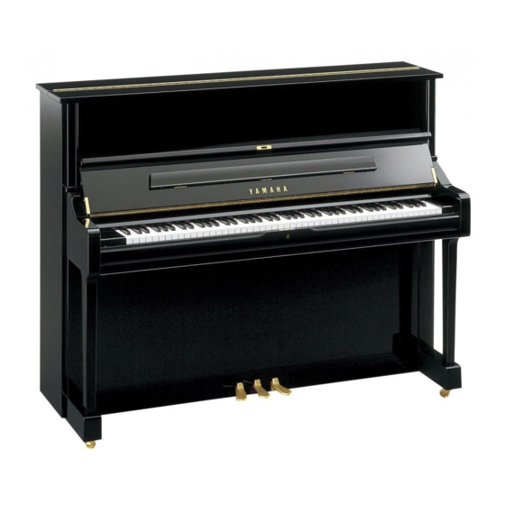
Summary of Contents for Yamaha Silent Piano SG Series
- Page 1 MAINTENANCE HANDBOOK UP Silent SG Series MHB30 Jan 2012 Ver. 1.0...
-
Page 2: Table Of Contents
Foreword This handbook covers maintenance for the Upright Piano Silent SG released in October 2006. For additional information, see SILENT SG SERIES Service manual PP008613 Table of Contents 1. Unit structure and Specifications ---------------------------------------- 2. Adjustment / Checking points --------------------------------------- 3. -
Page 3: Unit Structure And Specifications
1. Unit Structure and Specifications ①Switch Box ②Shift Pedal ③Center Pedal *Sostenuto Pedal ④Damper Pedal ① *Silent lever ② ④ ③ *for model YUS5 and SU7 only Fig.1 Fig.2... - Page 4 ・Right side view ⑥ ⑤ Key Sensor Unit -Key sensor unit adjustment ⇒P.8 -Key sensor measurement ⇒P.9 ⑤ ⑥ Hammer Shank Stopper -Check / adjustment ⇒P.7 Fig.3 ・Front view ⑦ *Silent Lever -Stroke adjustment of Silent lever Stroke adjustment screw ⑦ ⑧ Soft Pedal Sensor Soft sensor ON/OFF -How to check / adjust the sensor detection position ⇒P.11...
-
Page 5: Adjustment / Checking Points
2. Adjustment / Confirmation Items Adjustment item Description Ref. page Lower Front Board removal ・Remove the switch box ⇒P.6 caution ⇒P.6 ・Disconnect three cables Silent mechanism ⇒P.7 ・Check / adjustment ・Check / adjustment of hammer shank stopper ⇒P.7 ⇒P.7 ・Hammer shank stopping position adjustment ... -
Page 6: Piano Regulation Caution
3. Piano regulation caution 1) Removing the Lower Front Board The switch box obstructs removal of the lower front board. Use the procedure shown on the right and remove the switch box before removing (opening) the lower front board. 1) Disconnect the three lines on the rear of the switch box. -
Page 7: Check / Adjustment Of Silent Mechanism
4.Check / Adjustment of Silent mechanism 1)Checking and Adjustment Shank Stop Position [Checking] Shank stop position : 4.5 to 7mm at each section in the following conditions ・Center pedal is depressed and locked to the left ・Hammers are moved towards the strings till they touch the shank stopper ・Check distance between the tip of the hammers and the strings 4.5 to 7.0mm Hammer shank stopper... -
Page 8: Sensor Unit Adjustment
3)Checking Let Off [Checking] Make sure that the let off is properly adjusted, and that the let off is completed before the shank makes contact with the shank stopper. Let Off: Shank stop position +1 to 2mm [Adjustment] Use the regulating button to adjust within the tolerance described above. 4)Checking and adjustment of the shank stopper height and width position [Height Adjustment] Perform the shank stopper height adjustment if each of the following problems is found... -
Page 9: Maintenance And Test Modes
6.Maintenance and Test Modes 1)Maintenance mode (measurement mode) Maintenance mode is a program for adjusting the key sensor and damper pedal sensor. Measurement by maintenance mode shall be required in the following cases; ・If the detection position is out of standard, when checked in the test mode. ・When replacing the key sensor rail, damper pedal sensor and DM sheet, etc. - Page 10 [Damper pedal sensor measurement] While the damper sensor detection position has been adjusted with VR on the sound sheet for the existing Silent series, this series applies half point position measurement for adjustment. Damper pedal sensor measurement procedure Measurement/ confirmation item Operation Measurement status notification 82F#+84G#+86A#+ power ON...
- Page 11 ・Pedal sensor test 1A+3B+4C Adjust the pedal sensor sounding position with the sensor adjustment screw. The damper pedal is adjusted by measurement in the maintenance mode. [Damper Pedal] Pedal at rest : No Buzzer sound Pedal depressed slightly : Continuous tone (*1) Pedal half way down : Intermittent tone (*2) Pedal at stroke end...
-
Page 12: Checking Versions And Types
7.Checking versions and types Fig.18 [How to start] Turn on the power switch while pressing the A#-1 (2), C#0 (5), and D#0 (7) keys, and release the keys in two seconds. (Fig. 18) 1)Checking sensor information After the start-up, tones indicating sensor information will be sounded. The information can be confirmed by the number of piano sound notes. -
Page 13: Unit Connection Diagram
2)Checking tone generator information When the B-1 (3) key is pressed once during the checking of sensor information, tones indicating tone generator information will be sounded. The information can be confirmed by the number of piano sound notes. ①Tone generator type Starting from C3 (40), higher notes are sounded one by one as D3 (42), E3 (44). -
Page 14: Parts List
9.Parts List U1SG,YUS1SG U3SG,YUS3SG Model YUS5SG M112SG SU7SG U, V, W, A, K, E Destination U, A U, E V, W, A, K Key Sensor Unit V9444200 V9444300 V9444400 V9444300 KEY SENSOR Circuit Board V8968400 Switch Box Unit AM Circuit Board WJ057300 WJ057400 DC-IN Circuit Board...
Need help?
Do you have a question about the Silent Piano SG Series and is the answer not in the manual?
Questions and answers