
Related Manuals for Minuteman 957724 PRIME

Summary of Contents for Minuteman 957724 PRIME
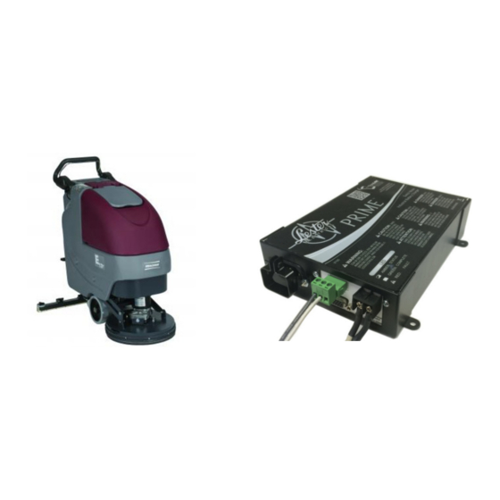
- Page 1 MODEL: E17/E20 DOCUMENTED BY: Jonathan Sanchez DATE: 06/20/18 957724 PRIME Charger INSTALLATION P/N 999081...
- Page 2 CHARGER INSTALLATION Using the (3x) included #10‐24x3/4” flat Angle the charger unit (p/n: 957724) as Install lower (2x) #8‐32x3/8” pan head head machine screws (p/n: 712544), attach shown to insert inside electrical control machine screws (p/n: 711133) by using a the Charger Adapter Plate (p/n: 172089) to box.
- Page 3 CHARGER WIRING Remove indicator light cap (fig. 2) and insert plastic lock nut through indicator light assembly (fig. 3). Insert light end of assembly through the opening on the machine’s back panel (fig. 4) and insert cover over light housing (fig. 5). Re‐install indicator light cap and secure onto back panel by tightening the retaining ring on the rear of the Attach indicator light wiring into the port as shown (fig.
- Page 4 WIRING Attach indicator light onto back‐panel if this has not been attached yet. Attach common wire, from battery, into Lockout 2. See page 3 for exact details. Attach harness wire, from harness, into Lockout 1. P/N 999081...
- Page 5 DC OUTPUT WIRING Remove cap screw and attach black wire onto (A) and red wire onto (B) as shown. P/N 999081...
Need help?
Do you have a question about the 957724 PRIME and is the answer not in the manual?
Questions and answers