Table of Contents
Advertisement
Quick Links
Advertisement
Table of Contents

Related Manuals for ECS 761GXM-M2


Summary of Contents for ECS 761GXM-M2
- Page 3 Preface Copyright This publication, including all photographs, illustrations and software, is protected under international copyright laws, with all rights reserved. Neither this manual, nor any of the material contained herein, may be reproduced without written consent of the author. Version 1.0 Disclaimer The information in this document is subject to change without notice.
- Page 4 Declaration of Conformity This device complies with part 15 of the FCC rules. Operation is subject to the following conditions: • This device may not cause harmful interference, and • This device must accept any interference received, including interfer- ence that may cause undesired operation Canadian Department of Communications This class B digital apparatus meets all requirements of the Canadian Interference- causing Equipment Regulations.
-
Page 5: Table Of Contents
T T T T T ABLE OF CONTENTS ABLE OF CONTENTS ABLE OF CONTENTS ABLE OF CONTENTS ABLE OF CONTENTS Preface Chapter 1 Introducing the Motherboard Introduction....................1 Features.....................2 Motherboard Components............4 7 7 7 7 7 Chapter 2 Installing the Motherboard Safety Precautions................7 Choosing a Computer Case............7 Installing the Motherboard in a Case..........7... - Page 6 Power Management Setup............34 PCI/Plug and Play Setup .............35 BIOS Security Features..............36 CPU PnP Setup................36 Hardware Monitor...............37 Load Optimal Defaults..............38 Save Changes and Exit..............38 Discard Changes and Exit ............38 Chapter 4 Using the Motherboard Software About the Software CD-ROM............39 Auto-installing under Windows 2000/XP........39 Running Setup..............40 Manual Installation................42 Utility Software Reference ............42...
-
Page 7: Introducing The Motherboard
Chapter 1 Introducing the Motherboard Introduction Thank you for choosing the 761GXM-M2 motherboard. This motherboard is a high performance, enhanced function motherboard that supports Socket AM2 for AMD Athlon 64 FX/Athlon 64 X2 Dual-Core/Athlon 64/Sempron processors for high-end business or personal desktop markets. -
Page 8: Features
Feature Processor This motherboard uses socket AM2 that carries the following features: Accommodates AMD Athlon 64 FX/Athlon 64 X2 Dual-Core/Athlon 64/ • Sempron processors • Supports up to 2000 MT/s HyperTransport (HT) interface speeds HyperTransport Technology is a point-to-point link between two devices, it en- ables integrated circuits to exchange information at much higher speeds than cur- rently available interconnect technologies. - Page 9 Audio • Compliant with AC’97 v2.3 CODEC • Supports 6-channel audio CODEC designed for PC multimedia sys- tems • Provides three analog line-level stereo input with 5-bit volume control: Line-in, CD, AUX • Meets Microsoft WHQL/WLP 2.0 audio requirements Expansion Options The motherboard comes with the following expansion options: •...
-
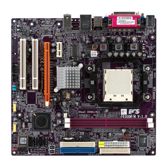
Page 10: Motherboard Components
Motherboard Components Introducing the Motherboard... - Page 11 Table of Motherboard Components LABEL COMPONENTS Socket AM2 for AMD Athlon 64 FX/Athlon 64 1. CPU Socket X2 Dual-Core/Athlon 64/Sempron CPUs 2. DDRII1~2 240-pin DDR2 SDRAM slots 3. IR1 Infrared header 4. CPU_FAN1 CPU cooling fan connector 5. PWR1 Standard 24-Pin ATX Power connector 6.
- Page 12 Memo Introducing the Motherboard...
-
Page 13: Installing The Motherboard
Chapter 2 Installing the Motherboard Safety Precautions • Follow these safety precautions when installing the motherboard • Wear a grounding strap attached to a grounded device to avoid dam- age from static electricity • Discharge static electricity by touching the metal case of a safely grounded object before working on the motherboard •... -
Page 14: Checking Jumper Settings
Do not overtighten the screws as this can stress the motherboard. Checking Jumper Settings This section explains how to set jumpers for correct configuration of the motherboard. Setting Jumpers Use the motherboard jumpers to set system configuration options. Jumpers with more than one pin are numbered. -
Page 15: Checking Jumper Settings
Checking Jumper Settings The following illustration shows the location of the motherboard jumpers. Pin 1 is labeled. Jumper Settings Type Description Jumper Setting (default) 1-2: CLEAR CMOS 2-3: NORMAL CLR_CMOS1 3-pin Clear CMOS Before clearing the CLR_CMOS1 CMOS, make sure to turn off the system. -
Page 16: Connecting Case Components
Connecting Case Components After you have installed the motherboard into a case, you can begin connecting the motherboard components. Refer to the following: Connect the CPU cooling fan cable to CPU_FAN1. Connect the system cooling fan connector to SYS_FAN1. Connect the case switches and indicator LEDs to the PANEL1. Connect the standard power supply connector to PWR1. - Page 17 CPU_FAN1: CPU cooling Fan Power Connector Signal Name Function System Ground +12V Power +12V Sense Sense Control Control Users please note that the fan connector supports the CPU cooling fan of 1.1A ~ 2.2A (26.4W max) at +12V. SYS_FAN1: FAN Power Connectors Signal Name Function System Ground...
-
Page 18: Front Panel Header
SPK1: Internal speaker Signal Name SPKR Front Panel Header The front panel header (PANEL1) provides a standard set of switch and LED headers commonly found on ATX or Micro ATX cases. Refer to the table below for informa- tion: Pin Signal Name Function Pin Signal Name Function... -
Page 19: Installing Hardware
Power Switch Supporting the power on/off function requires connecting pins 6 and 8 to a momen- tary-contact switch that is normally open. The switch should maintain contact for at least 50 ms to signal the power supply to switch on or off. The time requirement is due to internal de-bounce circuitry. - Page 20 CPU Installation Procedure The following illustration shows CPU installation components. Install your CPU. Pull up the lever away from the socket and lift up to 90-degree angle. Locate the CPU cut edge (the corner with the pin hold noticeably missing). Align and insert the CPU correctly.
-
Page 21: Installing Memory Modules
Installing Memory Modules This motherboard accommodates two 240-pin DIMM sockets (Dual Inline Memory Module) for unbuffered DDR2 800/667/533/400 memory modules (Double Data Rate SDRAM), and maximum 16 GB installed memory. DDR2 SDRAM memory module table Memory module Memory Bus DDR2 400 200 MHz DDR2 533 266 MHz... - Page 22 Table A: Unbuffered DIMM Address Timings and Drive Strengths for AM2 Package DRAM DIMM1 DIMM2 Timing Address Timing Output Driver Speed Mode Control Register Compensation Control Register DDR2-400 002F_2F2Fh X011_1222h DDR2-400 002F_2F2Fh X011_1322h DDR2-533 002F_2F2Fh X011_1222h SRx16 SRx16 DDR2-533 SRx16 SRx8 002F_2F2Fh X011_1322h...
- Page 23 Table B: DDR2 (memory module) QVL (Qualified Vendor List) The following DDR2 800/667/533 memory modules have been tested and qualified for use with this motherboard. Type Size Vendor Module Name CORSAIR 4PB11D9CHM CORSAIR AET94F-370 CORSAIR VC256MB533D2 4PB11D9CHM ELPIDA E2508AA-DF-E ELPIDA E2508AA-T7F-E Hynix HY5PS121621...
-
Page 24: Installing A Hard Disk Drive/Cd-Rom/Sata Hard Drive
Installing a Hard Disk Drive/CD-ROM/SATA Hard Drive This section describes how to install IDE devices such as a hard disk drive and a CD- ROM drive. About IDE Devices Your motherboard has a primary and secondary IDE channel interface (IDE1 and IDE2). - Page 25 About SATA Connectors Your motherboard features two SATA connectors supporting a total of two drives. SATA refers to Serial ATA (Advanced Technology Attachment) is the standard inter- face for the IDE hard drives which are currently used in most PCs. These connectors are well designed and will only fit in one orientation.
-
Page 26: Installing A Floppy Diskette Drive
Installing a Floppy Diskette Drive The motherboard has a floppy diskette drive (FDD1) interface and ships with a diskette drive ribbon cable that supports one or two floppy diskette drives. You can install a 5.25-inch drive and a 3.5-inch drive with various capacities. The floppy diskette drive cable has one type of connector for a 5.25-inch drive and another type of connector for a 3.5-inch drive. -
Page 27: Installing Add-On Cards
Installing Add-on Cards The slots on this motherboard are designed to hold expansion cards and connect them to the system bus. Expansion slots are a means of adding or enhancing the motherboard’s features and capabilities. With these efficient facilities, you can in- crease the motherboard’s capabilities by adding hardware that performs tasks that are not part of the basic system. - Page 28 Follow these instructions to install an add-on card: Remove a blanking plate from the system case corresponding to the slot you are going to use. Install the edge connector of the add-on card into the expansion slot. Ensure that the edge connector is correctly seated in the slot. Secure the metal bracket of the card to the system case with a screw.
-
Page 29: Connecting Optional Devices
Connecting Optional Devices Refer to the following for information on connecting the motherboard’s optional devices: F_AUDIO1: Front Panel Audio header This header allows the user to install auxiliary front-oriented microphone and line- out ports for easier access. Signal Name Signal Name Function AUD_MIC Front Panel Microphone input signal... - Page 30 F_USB1~2: Front Panel USB headers The motherboard has two USB ports installed on the rear edge I/O port array. Additionally, some computer cases have USB ports at the front of the case. If you have this kind of case, use auxiliary USB connector to connect the front-mounted ports to the motherboard.
- Page 31 SPDIFO1: SPDIF out header This is an optional header that provides an S/PDIF (Sony/Philips Digital Interface) output to digital multimedia device through optical fiber or coxial connector. Signal Name Function Signal Name Function SPDIF SPDIF-OUT Signal +5VA 5V analog power No pin Ground CD_IN1: Analog Audio Input header...
-
Page 32: Connecting I/O Devices
Connecting I/O Devices The backplane of the motherboard has the following I/O ports: PS2 Mouse Use the upper PS/2 port to connect a PS/2 pointing device. PS2 Keyboard Use the lower PS/2 port to connect a PS/2 keyboard. Parallel Port (LPT1) Use LPT1 to connect printer or other parallel commu- nication devices. -
Page 33: Using Bios
Chapter 3 Using BIOS About the Setup Utility The computer uses the latest “American Megatrends Inc. ” BIOS with support for Windows Plug and Play. The CMOS chip on the motherboard contains the ROM setup instructions for configuring the motherboard BIOS. The BIOS (Basic Input and Output System) Setup Utility displays the system’s configuration status and provides you with options to set system parameters. - Page 34 Press DEL to enter SETUP Press the delete key to access the BIOS Setup Utility. CMOS Setup Utility -- Copyright (C) 1985-2005, American Megatrends, Inc. Standard CMOS Setup CPU PnP Setup Advanced Setup Hardware Monitor Features Setup Load Optimal Settings Power Management Setup Save Changes and Exit PCI/Plug and Play Setup...
-
Page 35: Updating The Bios
Updating the BIOS You can download and install updated BIOS for this motherboard from the manufacturer’s Web site. New BIOS provides support for new peripherals, improve- ments in performance, or fixes for known bugs. Install new BIOS as follows: Create a bootable system disk. (Refer to Windows online help for information on creating a bootable system disk.) Download the Flash Utility and new BIOS file from the manufacturer’s Web site. -
Page 36: Standard Cmos Setup
Standard CMOS Setup This option displays basic information about your system. CMOS Setup Utility -- Copyright (C) 1985-2005, American Megatrends, Inc. Standard CMOS Setup System Time 00 : 47 : 28 Help Item System Date Mon 05/12/2006 User [Enter], [TAB] Primary IDE Master Hard Disk or [SHIFT-TAB] to... -
Page 37: Advanced Setup
Advanced Setup This page sets up more advanced information about your system. Handle this page with caution. Any changes can affect the operation of your computer. CMOS Setup Utility - Copyright (C) 1985-2005, American Megatrends, Inc. Advanced Setup Help Item Share Memory 64 MB Quick Boot... -
Page 38: Features Setup
Spread Spectrum (Disabled) If you enable spread spertrum, it can significantly reduce the EMI (Electro-Magnetic interface) generated by the system.and voltage according to its temperature. Features Setup This page sets up more advanced information about your system. Handle this page with caution. - Page 39 OnBoard PCI IDE Controller (Both) Use this item to enable or disable both of the onboard Primary and Secondary IDE channels. OnBoard PCI S-ATA Controller (IDE) Use this item to enable the onboard PCI SATA Controller. Onboard AC97 Audio DEVICE (Enabled) This item enables or disables the AC’97 audio chip.
-
Page 40: Power Management Setup
Power Management Setup This page sets up some parameters for system power management operation. CMOS Setup Utility - Copyright (C) 1985-2005, American Megatrends, Inc. Power Management Setup Help Item ACPI Aware O/S Power Management Enabled Suspend mode Enable /Disable Suspend Time Out Disabled ACPI support for Resume On RTC Alarm... -
Page 41: Pci/Plug And Play Setup
LAN/Ring Power On (Disabled) The system can be turned off with a software command. If you enable this item, the system can automatically resume if there is an incoming call on the Modem/ Ring, or traffic on the network adapter. You must use an ATX power supply in order to use this feature. -
Page 42: Bios Security Features
BIOS Security Features This item helps you install or change a password. CMOS Setup Utility - Copyright (C) 1985-2005, American Megatrends, Inc. BIOS Security Features Security Settings Help Item Supervisor Password: Not Installed Install or Change the Change Supervisor Password Press Enter password. -
Page 43: Hardware Monitor
CPU OVERCLOCK (200) This item decides the CPU over-clocking function installed in your system. If the over-clocking fails, please turn off the system power. And then, hold the PageUp key (similar to the Clear CMOS function) and turn on the power, the BIOS will recover the safe default. -
Page 44: Load Optimal Defaults
Smart Fan Control (Disabled) This item enables or disables the control of the system fan speed by adjusting the fan parameter. Press <Esc> to return to the Hardware Monitor setup page. System Component Characteristics These items display the monitoring of the overall inboard hardware health events, such as System &... -
Page 45: Using The Motherboard Software
Chapter 4 Using the Motherboard Software About the Software CD-ROM The support software CD-ROM that is included in the motherboard package contains all thedrivers and utility programs needed to properly run the bundled products. Below you can finda brief description of each software program, and the location for your motherboardversion. -
Page 46: Running Setup
Setup Tab Setup Click the Setup button to run the software installation program. Select from the menu which software you want to install. The Browse CD button is the standard Windows command that Browse CD allows you to open Windows Explorer and show the contents of the support CD. - Page 47 Click Next. The following screen appears: Check the box next to the items you want to install. The default options are recom- mended. Click Next run the Installation Wizard. An item installation screen appears: Follow the instructions on the screen to install the items. Drivers and software are automatically installed in sequence.
-
Page 48: Manual Installation
Manual Installation Insert the CD in the CD-ROM drive and locate the PATH.DOC file in the root directory. This file contains the information needed to locate the drivers for your motherboard. Look for the chipset and motherboard model; then browse to the directory and path to begin installing the drivers. -
Page 49: Sis965L Sata Raid Setup Guide
Chapter 5 SiS965L SATA RAID Setup Guide Introduction for SiS965L SATA RAID Function The SiS965L S-ATA Host controller only support two serial ATA on two independent ports. The Serial ATA RAID is designed to provide a cost-effective, high perfor- mance RAID solution that adds performance and/or reliability to PC desktops and/or servers using Serial ATA/150 hard disks. -
Page 50: Installing Software Drivers
JBOD: (Just a Bunch of Drives). Also known as “Spanning”. Two or more hard drives are required. Several hard disk types configured as a single hard disk. The hard drives are simply hooked up in series. This expands the capacity of your drive and results in a useable total ca- pacity. -
Page 51: Bios Utility Operation
Confirming Windows 98/Me Driver Installation From Windows 98/Me, open the Control Panel from “My Computer” followed by the System icon. Choose the “Device Manager” tab. Click the “+” in front of “IDE ATA/ATAPI Controllers” hardware type. The driver “SiS 180 IDE Dual Channel” and “SiS 180 IDE/RAID Control- ler”... - Page 52 Create RAID • SiS965L controller support RAID 0, RAID 1 and JBOD. Creating a RAID 0 (Stripe) Array for Performance • SiS 180 enables users to create striped arrays with 2, 3, or 4 drives. • SiS965L only supports 2 SATA drivers to create a stripe array. To create an array for best performance, follow these steps: Press <A>...
- Page 53 Use < ↑ > < ↓ > to select disk, and press <Enter> to select disk, <Q> to exit. When you press <Enter> on the disk you wanted, the RAID Type will be changed from Single to RAID 0. An the disk you select first will be the SOURCE disk.
- Page 54 Press <Q> again to exit this BIOS utility and the red message frame will show. Press <Y> and <Enter> to save changes. Once the array has been created, you will need to FDISK and format the array as if it were a new single hard drive. Creating a RAID 1 (Mirror) Array SiS 965L/180 enables users to create Mirror arrays with 2 drives only.
- Page 55 Use < ↑ > < ↓ > to select disk, and press <Enter> to select disk, <Q> to exit. When you press <Enter> on the disk you wanted, the RAID Type will be changed from Single to RAID 1. The same as RAID 0, the disk you select first will be the SOURCE disk.
- Page 56 Press <Q> again to exit this BIOS utility and the red message frame will show as the same as the creation of the RAID 0 array. Press <Y> and <Enter> to save changes. Once the array has been created, you will need to FDISK and format the array as if it were a new single hard drive.
- Page 57 Press <Q> again to exit this BIOS utility and the red message frame will show as the same age as the creation of the RAID 0 array. Press <Y> and <Enter> to save changes. Once the array has been created, you will need to FDISK and format the array as if it were a new single hard drive.
- Page 58 Memo...
Need help?
Do you have a question about the 761GXM-M2 and is the answer not in the manual?
Questions and answers