
Subscribe to Our Youtube Channel
Related Manuals for Rosslare CP-R25


Summary of Contents for Rosslare CP-R25
- Page 1 CP-R25 & AS-B01 Desktop MIFARE and fingerprint card programmer and Software Hardware & Software Manual November 2009...
-
Page 3: Table Of Contents
Table of Contents Table of Contents 1. Introduction ................4 1.1 The CP-R25 System ............. 4 1.2 Desktop Convenience ............4 1.3 Intuitive Software System ............. 5 1.4 Compatibility ..............5 1.5 Main Features ..............5 1.6 CP-R25 Desktop Programmer ..........5 1.7 AS-B01 Software .............. - Page 4 7.2 Card Overwrite ..............37 Appendix A. Maintenance ............38 Appendix B. Field Descriptions ..........41 Appendix C. Additional MIFARE Card Memory Map Information ................44 Appendix D. Sample Worksheets..........46 Appendix E. Limited Warranty ..........47 Appendix F. Technical Support ..........49 Page iii CP-R25 Hardware & Software Manual...
-
Page 5: Introduction
1.1 The CP-R25 System The CP-R25 is built for high-security, portability and ease of use, enabling high quality MIFARE and fingerprint enrollment at a low cost. -
Page 6: Intuitive Software System
Using this tool requires basic understanding of MIFARE cards memory architecture and access condition mechanisms. The software does not support all MIFARE cards features required by the systems using the CP-R25 programmed MIFARE cards. 1.4 Compatibility The CP-R25 Desktop Programmer and AS-B01 software are compatible with other products, including but not limited to: •... -
Page 7: As-B01 Software
1.7 AS-B01 Software • Programs fingerprints on Users cards • Programs ID data on Users cards • Produces configuration cards for Rosslare MIFARE readers • Performs firmware updates on supported desktop programmers • Maintains a user log to provide feedback to the software user •... -
Page 8: Specifications And Requirements
Specification – 2% (1/50) Electrical Specifications Operating Voltage 5V DC Via USB Input Current 75mA (standby) 160mA (maximum) CP-R25 Physical Specifications Dimensions 17.3x5.8x3.3 cm 6.18x2.28x1.30 inch (L x W x H) Weight 309g (10.89 oz) Page 7 CP-R25 Hardware & Software Manual... -
Page 9: As-B01 Software Requirements
0 - 95% (non condensing) 2.2 AS-B01 Software Requirements Minimum Software Requirements Operating System Windows XP SP2 Framework Microsoft .NET 2 Processor 400MHz Pentium or equivalent RAM Memory 512 Mbytes Free HD space: 1 Gigabyte Connection Port CP-R25 Hardware & Software Manual Page 8... -
Page 10: Installation
Installation Installation 3.1 Unpacking the Equipment The CP-R25 programmer is ready to use immediately "out of the box" and includes a USB cable and documentation. Please confirm all the items listed below are received before beginning. If any items are missing, contact your dealer immediately. -
Page 11: As-B01 Software Installation
AS-B01 installation. The installation package extracts the installation files. After the files are extracted the "Welcome to the CP-R25 Setup Wizard" window is displayed. Figure 3: AS-B01 Setup – Welcome Screen 3. - Page 12 Figure 4: AS-B01 Setup – Select Installation Folder 4. Select the folder to install the software. In the Folder field the Rosslare default location is displayed. If another location is required click Browse. The standard Windows Explorer window is displayed. Navigate to and select the required folder.
- Page 13 Figure 6: ASB01 Setup – Confirm Installation 7. Click Next to continue the installation process. The Installation Complete window is displayed. Figure 7: ASB01 Setup – Installation Complete 8. Click Close to complete the installation process. CP-R25 Hardware & Software Manual Page 12...
-
Page 14: Cp-R25 Hardware Installation
Before connecting the CP-R25 hardware ensure that the ASB01 software is installed. Connecting the CP-R25 requires two steps. First the AS-B01 software must be operating, and then the CP-R25 can be connected. To connect the CP-R25: 1. Click on the AS-B01 icon on the desktop, or select the program from the Rosslare folder in the "Start"... - Page 15 Installation Figure 9: AS-B01 – Main Window At the bottom left of the Main window the CP-R25 connection indication is red with the description Disconnected. 3. Connect the Desktop Programmer to a PC using the USB cable. One cable end connects to PC USB host port output and the other end connects to the USB connector on the Desktop Programmer.
- Page 16 Disconnected after the USB cable is connected, try disconnecting the USB cable from the Desktop Programmer and reconnecting it. Once the indicator is green and the description is Connected the CP-R25 Desktop Programmer is now ready for use. Page 15 CP-R25 Hardware & Software Manual...
-
Page 17: As-B01 Software Overview And Leds
AS-B01 Software Overview and LEDs AS-B01 Software Overview and LEDs This section explains how to start the software and login to the main window as well as describe the AS-B01 and CP-R25 LEDs. 4.1 Starting the Software To start the software: 1. -
Page 18: Software Overview
Descriptions for fields requiring parameters under all the tabs are described in Appendix A. • There are two programming tabs: Sector reader – Used to configure and read sector reader cards. This tab allows configuration of both Page 17 CP-R25 Hardware & Software Manual... -
Page 19: Indication Led's
• Status information area – indicates connection status with the CP-R25 Desktop Programmer hardware. 4.3 Indication LED’s: The following table describes LED behavior on the CP-R25 Programmer (see Figure 2: CP-R25 Description). General Event Swipe Card... - Page 20 Read finger timeout – when no finger is passed over the scanner for 30 seconds, the CP-R25 Desktop Programmer goes back to standby mode of swipe LEDs. Page 19 CP-R25 Hardware & Software Manual...
-
Page 21: Programming Cards And Tags
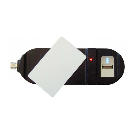
Operation Type drop down menu. When programming a MIFARE card or tag, the card or tag is placed on the CP-R25 Desktop Programmer antenna area. The following figure illustrates where these areas are located on the CP-R25 Desktop Programmer. -
Page 22: Programming Configuration Cards
Programming Cards and Tags Figure 15: CP-R25 Antenna Areas The CP-R25 Programmer configures two card or tags types. The two card types are: • Configuration Card – this card is used to configure a reader upon power up during the initial setup. The... -
Page 23: Sector Reader Configuration Cards
8. For readers with a Keypad, check the Keypad select box, further keypad options will appear. Set the Programming code, select the backlight behavior in the Backlight options dropdown menu, and set the CP-R25 Hardware & Software Manual Page 22... -
Page 24: Fingerprint Swipe Reader Configuration Cards
12 hexadecimal digit with the format FFFFFFFFFFFF. 10. Place a blank MIFARE card or a card previously configured as a Configuration Card on the CP-R25 Desktop Programmer antenna area. 11. Click Start to begin programming the MIFARE card. -
Page 25: Programming User Cards Or Tags
12 hexadecimal digit with the format FFFFFFFFFFFF. 11. Place a blank MIFARE card or a card previously configured as a Configuration Card on the CP-R25 Desktop Programmer antenna area. 12. Click Start to begin programming the MIFARE card. -
Page 26: Programming A Sector Read User Card
Number, and Byte Number fields. Note: If Card serial number is being used by the organization, no programming is available for the user card. 3. Ensure that the Operations is set to Program Card. Page 25 CP-R25 Hardware & Software Manual... -
Page 27: Programming And Enrolling Fingerprint User Card
8. Type the User Card ID or scroll using the Up and Down arrows. The value can be between 0 and 16777215 9. Place a MIFARE card on the CP-R25 Desktop Programmer antenna area. 10. Click Start to begin programming the MIFARE card. - Page 28 10. For Sector Operation Mode, type the User Card ID or scroll using the Up and Down arrows. The value can be between 0 and 16777215. 11. Place a MIFARE card on the CP-R25 Desktop Programmer antenna area. Page 27...
- Page 29 If the programming is a failure there is a short buzz and the swipe Card Reader LEDs lights red for three seconds. To program and enroll additional user cards, repeat steps 10 to CP-R25 Hardware & Software Manual Page 28...
-
Page 30: Additional Programmer Utilities
2. In the Operations area select Card utilities. 3. In the Operation Type field, select Read Configuration Card from the drop down menu. 4. Place the MIFARE Configuration Card on the CP-R25 Desktop Programmer antenna area. Page 29 CP-R25 Hardware & Software Manual... -
Page 31: Reading An Id From A User Card
7. For security reasons, type the KeyA for the card being read. 8. Place the MIFARE User Card on the CP-R25 Desktop Programmer antenna area. 9. Click Start to display the card ID in the MIFARE User Card ID field. -
Page 32: Changing The User Card Keya In A Specific Sector
The value can be between 0 and 16777215. 9. Define the ID Location using the Sector Number, Block Number, and Byte Number fields. 10. Place the MIFARE User Card on the CP-R25 Desktop Programmer antenna area. 11. Click Start to begin programming procedure. -
Page 33: Changing Keya And Erasing All Data
5. Type the same value in the New KeyA and the Confirm New KeyA fields, enter the Current KeyA of the card being programmed. 6. Place the MIFARE User Card on the CP-R25 Desktop Programmer antenna area. 7. Click Start to start the formatting procedure. -
Page 34: Read Serial Number And Card Type
Number, Block Number, and Byte Number fields. 7. For security reasons, type the KeyA for the card being read. 8. Place the MIFARE User Card on the CP-R25 Desktop Programmer antenna area. 9. Click Start to erase the data from the specific sector within the card. -
Page 35: Fingerprint Utilities
KeyA value, type the same value in the New KeyA, the Confirm New KeyA, and the Current KeyA fields. 7. Place the card on the CP-R25 Desktop Programmer antenna area. 8. Click Start to begin programming the MIFARE card. -
Page 36: Verifying Fingerprint Enrollment On A User Card
KeyA value, type the same value in the New KeyA, the Confirm New KeyA, and the Current KeyA fields. 6. Place the card on the CP-R25 Desktop Programmer antenna area. 7. Click Start to begin programming the MIFARE card. -
Page 37: Global Options
4 letters long. Mixing letters and numbers also substantially strengthens the password. All passwords are hidden by '*' characters, to avoid exposing it to an unauthorized user. 3. Click OK. The password is changed. CP-R25 Hardware & Software Manual Page 36... -
Page 38: Card Overwrite
To enable Card Overwrite warning: 1. In the File menu click Options Card overwrite. The Overwrite pop-up window appears Figure 17: Enable Card Overwrite Pop-up Window 2. Check the checkbox to enable warning.. 3. Click OK. Page 37 CP-R25 Hardware & Software Manual... -
Page 39: Appendix A. Maintenance
• Avoid dropping the unit onto the ground. This may cause electromechanical failure. • When required update the firmware To update the CP-R25 Desktop Programmer firmware: 1. In the File menu click Options Firmware Programming. The Desktop Reader Firmware Programming window is displayed. - Page 40 Maintenance 5. Make sure USB cable is disconnected from the CP-R25 Desktop Programmer. If the cable is still connected, a window requesting the cable be disconnected is displayed. The indicator at the left bottom side of the screen displays Disconnected.
- Page 41 Maintenance CP-R25 Hardware & Software Manual Page 40...
-
Page 42: Appendix B. Field Descriptions
Field Descriptions Appendix B. Field Descriptions The AS-B01 software application has fields that need to be completed when configuring the CP-R25 Desktop Programmer, MIFARE cards and / or tags. The following table describes these fields. Field Name Description Card Serial Number In the "Operation Mode"... - Page 43 The MIFARE card storage is divided into sectors with each sector being protected by two different keys, KeyA and KeyB. These keys are programmable according to company security specifications. KeyB is not supported. CP-R25 Hardware & Software Manual Page 42...
- Page 44 MIFARE User Card ID Unique ID assigned to the card. This ID number is obtained from the company security officer. The ID number is a numeric with a range of 0 – 16777215. Page 43 CP-R25 Hardware & Software Manual...
-
Page 45: Appendix C. Additional Mifare Card Memory Map Information
IC manufacturer at production. When the Rosslare MIFARE reader operation mode is configured to "card serial number", the Unique ID (UID) of the card is read from manufacture block. - Page 46 Additional MIFARE Card Memory Map Information Figure: 21 MIFARE 1K Memory Diagram For further details about MIFARE cards refer to the NXP Semiconductor MIFARE datasheet. Page 45 CP-R25 Hardware & Software Manual...
-
Page 47: Appendix D. Sample Worksheets
ID Location – Sector Number ID Location – Block Number ID Location – Byte Number MIFARE User Card ID Number of Fingerprints (1 or 2) LED Control Buzzer Control Lockout Attempts Lockout Duration Batch Order Code CP-R25 Hardware & Software Manual Page 46... -
Page 48: Appendix E. Limited Warranty
2 years (24 Months). Warranty Remedy Coverage In the event of a breach of warranty, ROSSLARE will credit Customer with the price of the Product paid by Customer, provided that the warranty claim is delivered to ROSSLARE by the Customer during the warranty period in accordance with the terms of this warranty. - Page 49 This warranty shall not extend to any ancillary equipment not furnished by ROSSLARE, which is attached to or used in conjunction with a Product, nor to any Product that is used with any ancillary equipment, which is not furnished by ROSSLARE.
-
Page 50: Appendix F. Technical Support
Rosh HaAyin, Israel 48091 Tel: +972 3 938-6838 Fax: +972 3 938-6830 E-mail: support.eu@rosslaresecurity.com South America Pringles 868, 1640 Martinez Buenos Aires Argentina Tel: +54 11 4798-0095 Fax: +54 11 4798-2228 E-mail: support.la@rosslaresecurity.com Web Site: www.rosslaresecurity.com Page 49 CP-R25 Hardware & Software Manual... - Page 52 www.rosslaresecurity.com...
Need help?
Do you have a question about the CP-R25 and is the answer not in the manual?
Questions and answers