
Related Manuals for Rosslare AC-015


Summary of Contents for Rosslare AC-015
- Page 1 AC-015 Single-Door Access Control Programmer Hardware Installation and Programming Manual...
- Page 2 ROSSLARE. ROSSLARE reserves the right to revise and change this document at any time, without being obliged to announce such revisions or changes beforehand or after the fact.
-
Page 3: Table Of Contents
Changing from Secure Mode to Normal Mode ....... 20 Changing from Normal Mode to Bypass Mode ....... 21 Changing from Bypass Mode to Normal Mode ....... 21 Events and Event Actions ......... 22 Tamper Event ................ 22 AC-015 Hardware Installation and Programming Manual... - Page 4 10.11 Return to Factory Default Settings .......... 33 10.12 Changing the Facility Code ............ 33 10.13 Replacing a Lost Programming Code ........34 10.14 Replacing Lost Normal/Secure Code ........35 Limited Warranty ............36 AC-015 Hardware Installation and Programming Manual...
- Page 5 List of Figures List of Figures Figure 1: AC-015 Controller Layout ..............15 Figure 2: Power Wiring ..................16 Figure 3: Typical Lock and Option Wiring ............16 Figure 4: Reader Wiring ................... 17 Figure 5: Connecting a Controller to a PC ............17...
- Page 6 List of Tables List of Tables Table 1: Programming Menu Quick Reference Guide ........24 AC-015 Hardware Installation and Programming Manual...
- Page 7 ROSSLARE exclusive warranty and liability is limited to the warranty and liability statement provided in an appendix at the end of this document. ...
-
Page 8: Introduction
The AC-015 provides a higher level of security as the programmer is normally placed in a secure location while the reader sensor is remotely located outside the premises to be controlled. Should the... -
Page 9: Key Features
A record form is enclosed for your reference to assist you with your record keeping. The AC-015 is capable of learning both PIN codes (keyboard based, 4- digit codes) and proximity codes (received from proximity card reader). - Page 10 Bell, Chime, and Strobe annunciator Programmable Lock Strike release time. Built-in Lock Strike suppressor diode. Comes with mounting template for easier installation. Built-in Reader power supply Built-in Lock Strike power supply AC-015 Hardware Installation and Programming Manual...
-
Page 11: Technical Specifications
Voltage: 12 VDC Max Current: 300 mA 2.1.3 Inputs N.O. Dry Contact Wiegand 26-Bit compatible Two Reader Inputs 2.1.4 Indicators and Annunciators Two tri-colored LEDs Visual Audio Built-in sounder (bell, chime & siren) Piezoelectric buzzer AC-015 Hardware Installation and Programming Manual... -
Page 12: Environmental Characteristics
Operating Humidity Range 0 to 95% (non-condensing) Mechanical Characteristics 134 x 85 x 30 mm (5.3 x 3.4 x 1.2 in.) Dimensions (L x W x D) (fits US Gang Box) Weight 220 g (7.76 oz) AC-015 Hardware Installation and Programming Manual... -
Page 13: Installation
Acid battery. Wiring diagrams are also provided for attaching the controller to the REX button, and external Wiegand 26-bit compatible readers. Also covered in this section is how to wire the AC-015 to a PC. Topics in this section: ... -
Page 14: Mounting The Controller
PC for easier programming and system maintenance. To mount the controller: If you are attaching the AC-015 to a US Gang Box, skip to Step 2. 1. Find the mounting template label that is provided in your AC-015 packaging, and place it at the location that you wish to install the controller. -
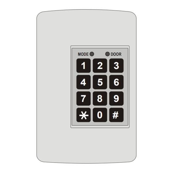
Page 15: Figure 1: Ac-015 Controller Layout
5. Wire the controller according to the diagrams on the next few pages. 6. Return and secure the front case using the security screw and security tool provided in the installation kit. You now have mechanically installed the controller. AC-015 Hardware Installation and Programming Manual... -
Page 16: Wiring
Figure 2: Power Wiring POWER SUPPLY FROM TRANSFORMER 16V AC (1.5A, 25VA) MODE DOOR 12V DC LEAD ACID BATTERY UP TO 7 AH RECOMMENDED Figure 3: Typical Lock and Option Wiring MODE DOOR N.C. N.O. Common N.C. AC-015 Hardware Installation and Programming Manual... -
Page 17: Figure 4: Reader Wiring
Figure 4: Reader Wiring MODE DOOR +12V +12V READER 12V DC, Max. 300mA READER 12V DC, Max. 300mA Figure 5: Connecting a Controller to a PC MODE DOOR To PC Serial Port (COM Port) AC-015 Hardware Installation and Programming Manual... -
Page 18: Modes Of Operation
Modes of Operation Modes of Operation The AC-015 has three modes of operation: Normal Mode Bypass Mode Secure Mode The three modes provide different levels of security. Normal Mode Mode Door The Mode LED is green. Green ... -
Page 19: Bypass Mode
In addition, it is possible to activate the Lock Strike in the following ways: Pressing the REX button Entering Master codes (from an outside reader only using a proximity code or a PIN code) AC-015 Hardware Installation and Programming Manual... -
Page 20: Changing The Modes Of Operation
To change from Secure mode to Normal mode: Mode Door 1. Enter the 4-digit Normal/Secure code. Mode Door Mode LED flashes green. Green 2. Press # to confirm the mode change. Mode Door The Mode LED turns green. Green AC-015 Hardware Installation and Programming Manual... -
Page 21: Changing From Normal Mode To Bypass Mode
To change from By pass mode to Normal mode: Mode Door 1. Enter the 4-digit Normal/Bypass code. Orange Mode Door Mode LED flashes green. Green 2. Press # to confirm the mode change. Mode Door The Mode LED turns green. Green AC-015 Hardware Installation and Programming Manual... -
Page 22: Events And Event Actions
Events and Event Actions Events and Event Actions Tamper Event A tamper event caused the AC-015 tamper output to open and alarm sound generated (if enabled). A tamper event may occur due to several reasons: AC-015 cover is removed or broken. -
Page 23: Rex Button
Lock Strike Release Time. In this case, the Lock Strike Relay only begins its count down once the REX button is released. When a door is opened with a REX button, no chime sound is generated. AC-015 Hardware Installation and Programming Manual... -
Page 24: Programming Instructions
This chapter describes how to program the AC- 015 using the programming keypad. Table 1 shows the names of all the AC-015 menus. It also shows of all the AC-015’s default factory codes and settings. Table 1: Programming Menu Quick Reference Guide... -
Page 25: Entering Programming Mode
Programming Instructions You must be in Normal mode to program the AC-015. The Mode LED is green. Wrong or timed out entries reset the controller to the Normal mode condition. To exit programming, press # for two seconds. Three beeps are generated and the system returns to Normal mode. -
Page 26: Exiting Programming Mode
Mode. While in Programming mode, if no key is pressed for 30 seconds the AC-015 emits a long beep and returns to Normal mode. A short press on # may also return the controller to Normal mode, accompanied by a long beep. -
Page 27: Changing Lock Strike Code 2
10.5 Changing the Programming Code To change the Programming code: 1. Enter Programming mode. Mode Door Green 2. Press 3. The Door LED remains green. Mode Door The Mode LED turns green. Green Green AC-015 Hardware Installation and Programming Manual... -
Page 28: Changing The Normal/Secure Code
015. You may set the code to 4 available options. To change the Normal/By pass code: Mode Door 1. Enter Programming mode. Green 2. Press 5. Mode Door The Mode indicator flashes orange. Orange Green AC-015 Hardware Installation and Programming Manual... -
Page 29: Changing The Fail Safe And Fail Secure Operations, Alarm Sound Time, And Door Release Time
To change the door release time: 1. Enter Programming mode. Mode Door Green 2. Press 6 to enter Menu 6. The Mode indicator flashes green. Mode Door Green Green 3. Construct a code using the following instructions: AC-015 Hardware Installation and Programming Manual... -
Page 30: Enrolling Proximity Cards/Tags And Keyboard Codes Into The System
Each proximity card is unique and can only be assigned to one slot at a time. If an unassigned proximity card is enrolled at an occupied slot, the AC-015 generates a long beep and waits for another slot number to be entered. The card at the current slot location must be erased before a new code is programmed on that slot number. - Page 31 Press # to move to the next slot number. If you do not wish to continue enrolling codes, press #. You hear a long beep and the controller returns to Normal mode. AC-015 Hardware Installation and Programming Manual...
-
Page 32: Deleting Proximity Codes
If the Programming code is valid, three beeps are heard and the controller returns to Normal mode. If the Programming code is invalid, a long beep is heard and the controller returns to Normal mode AC-015 Hardware Installation and Programming Manual... -
Page 33: Return To Factory Default Settings
To change the Facility code: 1. Enter Programming mode. Mode Door Green 2. Press 0. The Door LED flashes red. Mode Door 3. Press 1. The Mode LED flashes green. Mode Door Green Red AC-015 Hardware Installation and Programming Manual... -
Page 34: Replacing A Lost Programming Code
Programming mode so that you may create a new Programming code. The AC-015 must be in Normal mode; otherwise, this does not work. Make sure that the Mode LED is green before proceeding. 1. Disconnect power from the AC-015. -
Page 35: Replacing Lost Normal/Secure Code
Secure mode, perform the following procedure to re-enter Normal mode so that you may program a new Normal/Secure code. The AC-015 must be in Secure mode or this procedure does not work. Make sure that the Mode LED is red before proceeding. -
Page 36: Limited Warranty
The full ROSSLARE Limited Warranty Statement is available in the Quick Links section on the ROSSLARE website at www.rosslaresecurity.com. Rosslare considers any use of this product as agreement to the Warranty Terms even if you do not review them. AC-015 Hardware Installation and Programming Manual... - Page 37 +86 755 8610 6842 Canada Fax: +86 755 8610 6101 Rosslare Security Products, Inc. support.cn@rosslaresecurity.com Southlake, TX, USA Toll Free: +1-866-632-1101 India Local: +1-817-305-0006 Rosslare Electronics India Pvt Ltd. Fax: +1-817-305-0069 Tel/Fax: +91-20-40147830 support.na@rosslaresecurity.com Mobile: +91-9975768824 sales.in@rosslaresecurity.com Europe Rosslare Israel Ltd.
Need help?
Do you have a question about the AC-015 and is the answer not in the manual?
Questions and answers