Table of Contents
Advertisement
Quick Links
Advertisement
Table of Contents

Related Manuals for Traffic Logix SafePace 700


Summary of Contents for Traffic Logix SafePace 700
- Page 1 Traffic Logix ® SafePace® 700 Variable Message Installation Manual Radar Speed Sign Traffic Logix® I 3 Harriet Lane I Spring Valley, New York 10977 T (866) 915-6449 F (866)995-6449 www.trafficlogix.com I info@trafficlogix.com ©2014-2016 Traffic Logix® Corporation...
-
Page 2: Table Of Contents
Turning the Sign ON and OFF ....................13 Operating your sign ......................13 Maintaining your sign ......................14 Replacing key internal sign components ..................14 Warranty ..........................15 Technical Support ........................ 16 Copyright ©2014-2016 Traffic Logix® Corp. SafePace® 700: Installation Manual v1.4... -
Page 3: Introduction
Introduction Congratulations on your recent purchase of a Traffic Logix® SafePace® radar sign. They are a perfect choice for municipalities, residential neighborhoods, schools, police departments, private or gated communities, corporate campuses, schools and construction sites. These full featured signs are extremely versatile with the options you need at remarkably low pricing. -
Page 4: Overview
The display should be turned towards oncoming traffic so that it is clearly visible to approaching drivers (see Figure 3). The maximum detection range of the sign is 1,200 feet and varies based on the line of site (see Figure 4). Copyright ©2014-2016 Traffic Logix® Corp. SafePace® 700: Installation Manual v1.4... - Page 5 Figure 3, Symbolic Location Range of Detection up to 1,200 ft. Figure 4, Zone of Detection Copyright ©2014-2016 Traffic Logix® Corp. SafePace® 700: Installation Manual v1.4...
-
Page 6: Sign Assembly
Remove the breathers from their shipping bag and install by inserting them into the pre-cut mounting holes and securing with the supplied rubber washer and nut. Figure 5, Waterproof Breather Copyright ©2014-2016 Traffic Logix® Corp. SafePace® 700: Installation Manual v1.4... -
Page 7: Mounting The Sign
Tighten with a nut driver until secure (see Figure 7). Once secured, the sign is ready to be powered for use. Figure 7, Sign Secured to a Pole with Banding Strap Copyright ©2014-2016 Traffic Logix® Corp. SafePace® 700: Installation Manual v1.4... -
Page 8: Power Options
The Line (BLACK) and Neutral (WHITE) wires of the incoming power supply should be connected to the marked terminals. GROUND wire (usually GREEN), should be connected to the GREEN/YELLOW terminal (see Figure 6 above). Copyright ©2014-2016 Traffic Logix® Corp. SafePace® 700: Installation Manual v1.4... -
Page 9: Battery Power
TWO years. Improper care and maintenance of batteries may void product warranty. Batteries should always be wired in PARALLEL as depicted in Figure 9 below: Figure 9, Wiring Signs in Parallel Copyright ©2014-2016 Traffic Logix® Corp. SafePace® 700: Installation Manual v1.4... -
Page 10: Solar Power
For example, if the latitude of the installation site is 45 degrees then the solar panel should be installed at an angle of 60 degrees, as shown in Figure 12. Figure 12 Copyright ©2014-2016 Traffic Logix® Corp. SafePace® 700: Installation Manual v1.4... -
Page 11: Wiring The Solar Panel To The Sign
Slide the connectors together until you hear a click and you can no longer slide them apart easily. Once connected the cables should look like the following: Figure 16, Sign and Panel cables connected Copyright ©2014-2016 Traffic Logix® Corp. SafePace® 700: Installation Manual v1.4... - Page 12 This voltage regulator will be completely wired and configured when you receive the sign, so you do not need to make any changes to it. Figure 17, SunSaver-6 Voltage Regulator Copyright ©2014-2016 Traffic Logix® Corp. SafePace® 700: Installation Manual v1.4...
-
Page 13: Turning The Sign On And Off
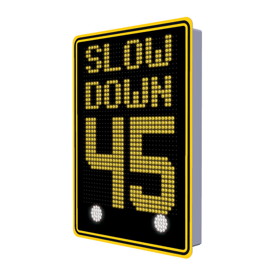
18" digits displaying vehicle speed. Choose any message, graphic, or animated text using the standard library provided or create your own library of custom messages to upload and display. Copyright ©2014-2016 Traffic Logix® Corp. SafePace® 700: Installation Manual v1.4... -
Page 14: Maintaining Your Sign
*If you suspect that you require a replacement of any of the above-mentioned components, please call Technical Support. If necessary, a Diagnostic Toolbox can be sent out to help trouble-shoot any issues you may be having. Copyright ©2014-2016 Traffic Logix® Corp. SafePace® 700: Installation Manual v1.4... -
Page 15: Warranty
THE IMPLIED WARRANTY OF FITNESS FOR A PARTICULAR PURPOSE ARE EXPRESSLY DISCLAIMED. Traffic Logix does not warrant that any of its products will meet or comply with the requirements of any applicable federal, state or local safety code, law, regulation or ordinance (“Applicable Safety Laws”). -
Page 16: Technical Support
Conditional Terms of Use or Applicable Safety Laws, or if the Product has been altered in any way by anyone other than Traffic Logix, or if the Product has been subject to any misuse or accident. In addition, Buyer assumes and agrees to indemnify Traffic Logix for all risk, liability or expense that results from any installation or use of the Product that is not in accordance with the Conditional Terms of Use or any Applicable Safety Laws.
Need help?
Do you have a question about the SafePace 700 and is the answer not in the manual?
Questions and answers