Table of Contents
Advertisement
Quick Links
Advertisement
Table of Contents

Related Manuals for Traffic Logix SafePace 700


Summary of Contents for Traffic Logix SafePace 700
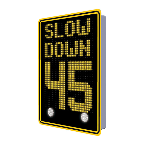
- Page 1 Traffic Logix ® SafePace® 700 Variable Message Radar Speed Sign Installation Manual Traffic Logix® I 3 Harriet Lane I Spring Valley, New York 10977 T (866) 915-6449 F (866)995-6449 www.trafficlogix.com I info@trafficlogix.com ©2014-2015 Traffic Logix® Corporation...
-
Page 2: Table Of Contents
Maintaining your sign ......................13 Replacing key internal sign components ..................13 Determining True South ....................... 14 Warranty ..........................16 Technical Support ........................ 17 2014-2015 Copyright Traffic Logix® Corp. SafePace® 700 Variable Message Radar Speed Sign Installation Manual V. 1.1... -
Page 3: Introduction
Introduction Congratulations on your recent purchase of a Traffic Logix® SafePace® radar sign. They are a perfect choice for municipalities, residential neighborhoods, schools, police departments, private or gated communities, corporate campuses, schools and construction sites. These full featured signs are extremely versatile with the options you need at remarkably low pricing. -
Page 4: Overview
The recommended height of the lower edge of the radar sign is approximately 7 feet above the surface of the road. 2014-2015 Copyright Traffic Logix® Corp. SafePace® 700 Variable Message Radar Speed Sign Installation Manual V. 1.1... - Page 5 (see Figure 3). The maximum detection range of the sign is 1,200 feet and varies based on the line of site (see Figure 4). Figure 3, Symbolic Location Range of Detection up to 1,200 ft. Figure 4, Zone of Detection 2014-2015 Copyright Traffic Logix® Corp. SafePace® 700 Variable Message Radar Speed Sign Installation Manual V. 1.1...
-
Page 6: Sign Assembly
Figure 5, Waterproof Breather 2014-2015 Copyright Traffic Logix® Corp. SafePace® 700 Variable Message Radar Speed Sign Installation Manual V. 1.1... -
Page 7: Mounting The Sign
Tighten with a nut driver until secure (see Figure 7). Once secured, the sign is ready to be powered for use. Figure 7, Sign Secured to a Pole with Banding Strap 2014-2015 Copyright Traffic Logix® Corp. SafePace® 700 Variable Message Radar Speed Sign Installation Manual V. 1.1... -
Page 8: Power Options
The Line (BLACK) and Neutral (WHITE) wires of the incoming power supply should be connected to the marked terminals. GROUND wire (usually GREEN), should be connected to the GREEN/YELLOW terminal (see Figure 6 above). 2014-2015 Copyright Traffic Logix® Corp. SafePace® 700 Variable Message Radar Speed Sign Installation Manual V. 1.1... -
Page 9: Battery Power
Batteries should always be wired in PARALLEL as depicted in Figure 9 below: Figure 9, Wiring Signs in Parallel 2014-2015 Copyright Traffic Logix® Corp. SafePace® 700 Variable Message Radar Speed Sign Installation Manual V. 1.1... -
Page 10: Solar Power
Begin by unscrewing the top fastener of the cable gland at the top right-hand side of the sign enclosure (Figure 12). Loosen it enough so that the solar panel wiring can be fed through. 2014-2015 Copyright Traffic Logix® Corp. SafePace® 700 Variable Message Radar Speed Sign... - Page 11 WARNING: Before ever doing any maintenance on a sign, it is critical that the power is first turned off. This will prevent accidental electrical shock that can be fatal and that can also damage electrical components. 2014-2015 Copyright Traffic Logix® Corp. SafePace® 700 Variable Message Radar Speed Sign Installation Manual V. 1.1...
- Page 12 No changes need to be made to the SunSaver. Figure 17, SunSaver-6 Voltage Regulator 2014-2015 Copyright Traffic Logix® Corp. SafePace® 700 Variable Message Radar Speed Sign Installation Manual V. 1.1...
-
Page 13: Turning The Sign On And Off
Battery (1) + Solar charger (1) - for signs powered by solar with rechargeable battery • AC Power convertor (1) - for AC powered sign configuration • Speed Violator Strobe PCB (2) 2014-2015 Copyright Traffic Logix® Corp. SafePace® 700 Variable Message Radar Speed Sign Installation Manual V. 1.1... -
Page 14: Determining True South
(where "local" and "current" are both important!). Most GPS units will also give the times for sunset and sunrise -- just make sure the GPS is set to your time zone. 2014-2015 Copyright Traffic Logix® Corp. SafePace® 700 Variable Message Radar Speed Sign... - Page 15 If your declination were 14 degrees west, you would rotate the compass until the needle was 14 degrees west of north on the bearing scale (it would point to 360 -14 = 346). 2014-2015 Copyright Traffic Logix® Corp. SafePace® 700 Variable Message Radar Speed Sign...
-
Page 16: Warranty
OR IMPLIED, INCLUDING, BUT NOT LIMITED TO THE IMPLIED WARRANTY OF MERCHANTABILITY AND THE IMPLIED WARRANTY OF FITNESS FOR A PARTICULAR PURPOSE ARE EXPRESSLY DISCLAIMED. Traffic Logix does not warrant that any of its products will meet or comply with the requirements of any 2014-2015 Copyright Traffic Logix® Corp. -
Page 17: Technical Support
Conditional Terms of Use or Applicable Safety Laws, or if the Product has been altered in any way by anyone other than Traffic Logix, or if the Product has been subject to any misuse or accident. In addition, Buyer assumes and agrees to indemnify Traffic Logix for all risk, liability or expense that results from any installation or use of the Product that is not in accordance with the Conditional Terms of Use or any Applicable Safety Laws.
Need help?
Do you have a question about the SafePace 700 and is the answer not in the manual?
Questions and answers