
Related Manuals for Traffic Logix SafePace 100 Series


Summary of Contents for Traffic Logix SafePace 100 Series
- Page 1 Traffic Logix SafePace 100 Radar Speed Sign Installation Manual Traffic Logix I 3 Harriet Lane I Spring Valley, New York 10977 T (866) 915‐6449 F (866)995‐6449 www.trafficlogix.com I info@trafficlogix.com ...
-
Page 2: Table Of Contents
Table of Contents 1.0 Overview .......................... 3 2.0 Available Models ......................... 3 3.0 Installation .......................... 3 3.1 Site Selection ........................ 3 3.2 Positioning the SafePace 100 .................... 4 3.3 Mounting the SafePace 100 .................... 5 3.3a Basic Banding Mounting (hardware included) .............. 5 3.3b Universal Mounting Bracket System (Optional) .............. 5 4.0 Sign Portability ........................ 9 5.0 Powering the SafePace 100 .................... 10 5.1 AC Power ........................... 10 5.2 Battery Power ........................ 10 5.3 Solar Power ........................ 12 5.3a Mounting the Solar Panel .................... 12 5.3b Wiring the Solar Panel to the SafePace 100 .............. 13 5.4 ... -
Page 3: Overview
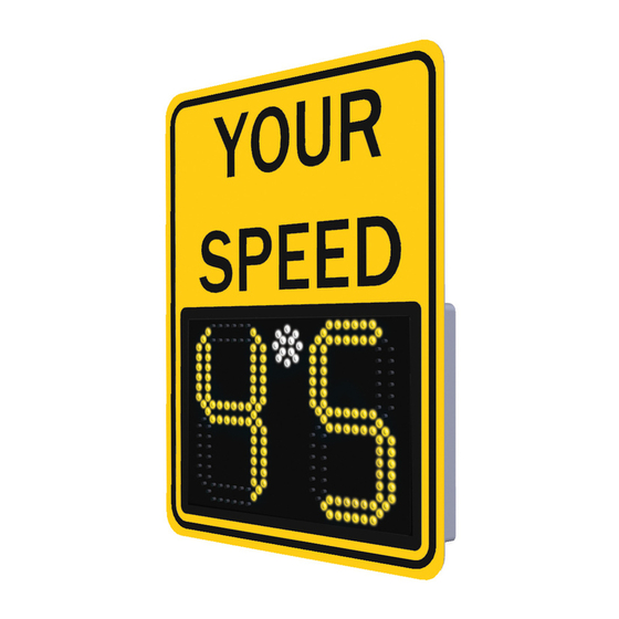
Overview The Traffic Logix SafePace 100 is an economical and portable radar speed sign. Compact and lightweight, it is a perfect choice for private or gated communities, corporate campuses, schools, construction zones and residential neighbourhoods. This full featured, low‐power sign offers the options you need at remarkably low pricing. 2.0 Available Models The SafePace 100 is available in the following models: SafePace 100 AC Powered SafePace 100 3 Cell Battery (3 Cell Lithium Battery – 2 week operation between charges) SafePace 100 4 Cell Battery (4 Cell Lithium Battery – 4 week operation between charges) SafePace 100 Solar Powered Installation There are several methods/hardware options available for the installation of the SafePace 100. 3.1 Site Selection Site selection varies with the application in which the SafePace 100 is being used. The following guidelines, however, should generally be adhered to: Choose a position where the line of sight from the radar sign to the vehicle will be uninterrupted. Consideration should be given to how the location may develop with time. The following types of questions should be considered: Will any trees grow directly in the line of vision? Is it likely that road traffic signs will be erected in a position that could obstruct the field of view? The radar sign should be installed directly adjacent to the lane of cars it is targeting since an interfering lane of traffic may cause inaccurate speed readings. iii) The structure that the radar sign is mounted to should be stable and firm. Avoid structures that are likely to be affected by wind or rain. The suggested pole type for installation is either a 4 inch diameter circular metallic pole or a 4 x 4 inch wooden pole is an ideal choice. If a Telespar pole is used, it is strongly advised that a 2 inch pole be used ... -
Page 4: Positioning The Safepace 100
3.2 Positioning the SafePace 100 Similar to other road signs, the SafePace 100 should be installed near the closest lane of traffic, although off the actual road. The recommended height of the lower edge of the radar speed sign is approximately 7 ft above the surface of the road. The display should be turned towards oncoming traffic so that it is clearly visible to approaching drivers. Figure 1, symbolic location Range of Detection up to 350 ft. Figure 2, zone of detection Page 4 2011 Copyright Traffic Logix Corp. SafePace 100: Installation Manual Ver. 2.0 ... -
Page 5: Mounting The Safepace 100
3.3 Mounting the SafePace 100 There are several methods and hardware options available to install the SafePace 100. 3.3a Basic Banding Mounting (hardware included) The SafePace 100 and optional solar panel should optimally be mounted on a 12 ‐14 foot pole. Standard Pole Banding Mounting Attach the supplied banding brackets to the top and bottom of the rear of the SafePace 100 with the supplied tamper‐proof, M6 security screws. Insert the stainless steel banding strap into the bracket and fasten the sign to the pole. Tighten with a nut driver until secure. See Figures 3 & 4 below. Figures 3 & 4, standard banding bracket mounted directly to sign with M6 tamper‐proof screws 3.3b Universal Mounting Bracket System (Optional) The SafePace 100 comes with an optional Universal Mounting Bracket that allows the sign to be easily mounted to virtually any type of pole or surface in a quick, easy and secure manner. The SafePace 100 mounts to the bracket and is just as easily removed from the bracket with just the turn of a key. The quick mount and dismount feature of this bracket readily allows the sign to be moved from one location to another with relative ease and convenience. Components: SafePace 100 Radar Sign Universal Mounting Bracket System (includes 1 sign bracket & 1 pole bracket) Installation Hardware (included) Page 5 2011 Copyright Traffic Logix Corp. SafePace 100: Installation Manual Ver. 2.0 ... - Page 6 Installing the Mounting Brackets Sign Bracket Attach the Sign Bracket to the backside of the SafePace 100 Radar Sign using the included hardware. Figures 5 &6: Use supplied hardware to mount the Sign Bracket to the rear of the SafePace 100 Pole Bracket The Pole Bracket can be secured to any type of standard pole or Telespar type pole by a choice of banding straps, lag screws, or bolts and nuts. Figure 7, Pole Bracket Figure 8, Pole Bracket mounted to circular pole mounted to 2” Telespar pole Page 6 2011 Copyright Traffic Logix Corp. SafePace 100: Installation Manual Ver. 2.0 ...
- Page 7 Installation of the Pole Bracket using supplied banding straps Figure 9 Figure 10 Figure 11 Pole bracket banded to Additional lag bolts should Profile view of pole utility pole be used for added security bracket banded NOTE: It is highly recommended that if banding is used to secure the Pole Bracket additional screws and/or bolts should also be used (see Figure 10 above) to further prevent theft and vandalism. Installation of Pole Bracket on Telespar Pole (Note: a 2 inch Telespar pole should be used) Use the supplied 2.5” stainless steel security bolts and nuts to secure the Pole Bracket to the 2” Telespar pole. Note: It is very important that the head of the bolt be placed on the Telespar pole (See Figures 12 and 13) and that the nuts be placed on the inside part of the bracket (see Figures 14 and 15). Figure 12 Figure 13 Figure 14 Figure 15 Page 7 2011 Copyright Traffic Logix Corp. SafePace 100: Installation Manual Ver. 2.0 ...
- Page 8 Mounting and Dismounting the SafePace 100 The SafePace 100 easily mounts by sliding the sign down onto the Pole Bracket and dismounts by sliding the sign up off of the Pole Bracket. Once mounted, the sign should be locked into place as shown in Figure 18. Figure 16 Figure 17 Figure 18 Step 1: Position the sign Step 2: Slide the sign down Step 3: Lock the sign in place. above the bracket. the bracket. WARNING: To prevent damage to the locking mechanism of the Universal Mounting Bracket System, the key must be removed from the lock and the locking mechanism must be set in the “unlocked” position (see picture on right) BEFORE sliding the sign ON or OFF of the Pole Locking Mechanism Bracket. in “unlocked” position Pole Bracket Banding strap holes (4) Teleapar pole mounting holes (6) U‐Channel mounting holes (4) Figure 19 Page 8 2011 Copyright Traffic Logix Corp. SafePace 100: Installation Manual Ver. 2.0 ...
-
Page 9: Sign Portability
Sign Portability The SafePace 100 is a very lightweight sign which used in conjunction with the optional Universal Mounting Bracket is quite portable. An optional, smaller, swivelling “YOUR SPEED” sign is available to make portability even easier. To swivel the “YOUR SPEED” sign, simply remove the two, outer tamper‐proof screws and swivel the sign downward until it completely covers the digits (see Figure below). Replace the two, outer screws to secure the sign for transport. Once the sign mounted in the new location, reverse the process and your sign will be ready to go in minutes. Figure 20, “YOUR SPEED” sign swivels down for easier transport Page 9 2011 Copyright Traffic Logix Corp. SafePace 100: Installation Manual Ver. 2.0 ... -
Page 10: Powering The Safepace 100
Powering the SafePace 100 The SafePace 100 is offered in several powering models. Depending on what model you have purchased, powering the sign will vary. 5.1 AC Power WARNING: ELECTRICAL SHOCK HAZARD To avoid serious injury or even death, all electrical wiring should be performed by a qualified and professional electrician in accordance with local electrical codes. Mishandling of electrical wiring may result in damage to the unit and may void product warranty. The SafePace 100 is equipped to accept 100‐240 volts of AC power. For these signs (standard model), the regulated power supply comes already prewired, and your sign is ready to operate once it is mounted and wired to the incoming power supply. The Line (BLACK) and Neutral (WHITE) wires of the incoming power supply should be connected to the marked terminals. The Ground wire should be connected to the GREEN/YELLOW terminal (see Figure 22 below). Figure 21, AC power supply terminal block Figure 22, close‐up view 5.2 Battery Power Signs that are powered by a Lithium battery come with either an optional 3 Cell 9.6 Ah battery or a 4 Cell 15.6 Ah battery. In most instances, the battery will be shipped already installed in the sign. At times, though, due to some shipping restrictions on Lithium batteries, the battery may be shipped separately. Once the battery is received, remove the battery from the shipping packaging. WARNING: the Lithium battery comes with a protective black wrap on the outside of the unit that SHOULD NEVER be removed; doing so will damage the battery and will create Page 10 2011 Copyright Traffic Logix Corp. SafePace 100: Installation Manual Ver. 2.0 ... - Page 11 a potential hazard. The Lithium batteries supplied with the SafePace 100 are stable and safe when handled and used properly. Care should be taken not to bend the battery or puncture it with sharp objects as fire and/or explosion may result. The battery should be charged fully before the initial use. The supplied battery charger is equipped with a charge indicator. When the light on the charger is RED (with the battery plugged into both the battery and an AC power outlet, the battery is charging. Once the light turns GREEN, the battery is now fully charged and is ready for use. The battery should be placed with care into the battery holder inside the sign. Before closing the door of the sign, ALWAYS make sure that the battery holder is closed and locked into place. Failure to do so may result in damage to the battery bracket and enclosure. To install the battery in the battery bracket, pull on the plunger pin on the upper bracket (see Figure 23 below) and open the bracket door. Gently insert the battery into the lower bracket and lay the battery flat against the enclosure. Next, gently close the battery bracket door and make sure the plunger pin locks into place. Once the battery is secured in the battery bracket, connect the battery and sign power connectors. Once connected, the sign will power on. Figure 23, bracket plunger pin Figure 24, battery bracket door Figure 25, battery secured Figure 26, battery and sign connectors Page 11 2011 Copyright Traffic Logix Corp. SafePace 100: Installation Manual Ver. 2.0 ...
-
Page 12: Solar Power
5.3 Solar Power Figure 27, solar panel Figure 28, solar panel mounting bracket The SafePace 100 Solar Power model comes standard with a small, compact 10 Watt solar panel and mounting, a 3 Cell 96 Ah Lithium battery, and a solar charger. The solar panel is quick to install and should suffice in most installations. 5.3a Mounting the Solar Panel The solar panel should be mounted at the highest point on the pole, optimally 10‐12 Feet high. Mount the sign using the supplied solar panel bracket (see Figure 28 above) and please follow the instructions provided by the manufacturer which are supplied in the bracket’s packaging. The two part bracket allows for full adjustment in order to best position the panel towards the sun. It is optimal to position your solar panel towards due Solar South (not magnetic South). Solar South is the position of the sun in sky exactly at the midpoint between sunrise and sunset. See Appendix A for techniques on how to determine Solar South for your installation site . The solar panel should be angled 15 degrees above the latitude of the installation site which can be readily ascertained from mapping software or free from mapping and travel direction websites on the internet. Page 12 2011 Copyright Traffic Logix Corp. SafePace 100: Installation Manual Ver. 2.0 ... -
Page 13: Wiring The Solar Panel To The Safepace 100
5.3b Wiring the Solar Panel to the SafePace 100 Figure 29, solar panel – front view Figure 30, solar panel, rear view To prevent damage to the solar charger, connect the Solar Panel wires to the Solar Charger (Step 1) BEFORE connecting the battery connectors (Step2). STEP 1 Connect solar panel wires to the solar charger STEP 2 Connect battery connectors Figure 31 Page 13 2011 Copyright Traffic Logix Corp. SafePace 100: Installation Manual Ver. 2.0 ... - Page 14 To wire the solar panel to the sign, pass the wire bundle from the solar panel through the water‐tight compression connector on the top of the sign (see Figures 32‐34). Next, carefully strip the protective sheath off of the wire bundle to expose the two inner wires (see Figures 35 & 36). Next, strip the BLACK and RED wires to expose bare wire. Connect the wires to the solar charger. The BLACK wire should be connected to the negative terminal marked Solar Panel ‐ and the RED wire should be connected to the positive terminal marked Solar Panel + (see Figures 37 & 38). Once the wires are securely connected, use the white mounting tabs with the zip ties to secure the wire to the body of the sign. Figure 32, wire bundle Figure 33, compression connector Figure 34 Figure 35, wire stripper Figure 36, wire leads (stripped) Figure 37, solar charger Figure 38, close‐up view of terminals; the BLACK wire from the solar panel is connected to the Negative, Solar Panel – terminal and the RED wire to the Positive, Solar Panel + terminal. Page 14 2011 Copyright Traffic Logix Corp. SafePace 100: Installation Manual Ver. 2.0 ...
-
Page 15: Real Time Clock Backup Battery Pack (For Data Collection)
5.4 Real Time Clock Backup Battery Pack (for Data Collection) For signs that have the Data Collection feature activated, a Real Time Clock backup battery pack is installed and is shown in Figure 39 below. This battery pack will preserve the sign’s Real Time Clock in the event that the main power source to the sign is interupted. This battery back should last for many years and should never need replacement during the life of the sign. IMPORTANT : Make sure that the two green terminal plugs on either side of the battery pack are plugged in at all times. Terminal Plug Terminal Plug Figure 39 5.5 Turning the SafePace 100 On and Off The SafePace 100 will immediately power on once the power source is connected. There is no ON/OFF switch supplied with the sign. To turn the sign off, simply disconnect the battery on the battery models and the connector on the AC and Solar models. To program and operate the SafePace 100, please refer to the SafePace 100 Software & User Manual. 6.0 Technical Support If you have questions or comments regarding the SafePace 100 radar speed sign, please feel free to contact our customer support center by phone: (866) 915‐6449 or by e‐mail: support@trafficlogix.com. Page 15 2011 Copyright Traffic Logix Corp. SafePace 100: Installation Manual Ver. 2.0 ... -
Page 16: Appendix A - Determining True South
Appendix A – Determining True South There are three ways to determine which way is true south. Google Earth You can use Google Earth to zero in on your house and find true south. This requires downloading a small program from the Google Earth site. Place the item you want to determine the direction of right in the center of the display, as the angles change as you pan around. In the “View” drop‐down menu, selecting "Grid" will display a latitude‐longitude grid in which the grid lines run in the north‐south and east‐west directions. Solar Noon Method This method uses the fact that the sun is always true south at solar noon. A shadow cast by a vertical object at solar noon runs true north‐south. So, at solar noon, use the shadow cast by a plumb‐bob string or the vertical edge of a building to determine true south. To determine the local time that corresponds to solar noon, find the sunrise and sunset times from a current local paper (where "local" and "current" are both important!). Most GPS units will also give the times for sunset and sunrise ‐‐ just make sure the GPS is set to your time zone. Solar noon is exactly half way between the sunrise and sunset time. Note that the difference between local time noon and solar noon can be quite a bit, depending on your location in the time zone, and daylight saving time. You can also use this NOAA solar time calculator to find the local time for solar noon at your location: http://www.srrb.noaa.gov/highlights/sunrise/sunrise.html Solar Noon South East West This Print Solar Noon Calendar prints out solar noon for your exact location for the entire year. Page 16 2011 Copyright Traffic Logix Corp. SafePace 100: Installation Manual Ver. 2.0 ... - Page 17 Compass Method You can use a magnetic compass to find south. The compass reading must be corrected for the magnetic declination in your area. Magnetic declination is the difference (in degrees) between the direction the compass needle points and true north. Magnetic Declination depends on your location. You can look up the declination for your area at: http://www.ngdc.noaa.gov/seg/geomag/jsp/Declination.jsp. Some compasses allow the declination to be set. If yours does, then just set your local declination and you are good to go. If not, then on each compass reading, you must offset the compass needle from the true north mark on the compass by the declination angle. For example, if you live in Bozeman, MT your declination is about 14 degrees east. To take a true compass bearing, rotate the compass until the needle points 14 degrees east of north on the compass bearing scale. If your declination were 14 degrees west, you would rotate the compass until the needle was 14 degrees west of north on the bearing scale (it would point to 360 ‐14 = 346). Tax Assessor Maps In some areas, tax assessors offer downloadable maps of your property that show true south. Page 17 2011 Copyright Traffic Logix Corp. SafePace 100: Installation Manual Ver. 2.0 ...
Need help?
Do you have a question about the SafePace 100 Series and is the answer not in the manual?
Questions and answers