Table of Contents
Advertisement
Quick Links
Advertisement
Table of Contents

Subscribe to Our Youtube Channel
Summary of Contents for Pepperl+Fuchs WCS-EIG310
- Page 1 WCS-EIG310 WCS Interface Module EtherNet/IP Manual...
- Page 2 Phone: +49 621 776 - 0 E-mail: info@de.pepperl-fuchs.com North American Headquarters Pepperl+Fuchs Inc. 1600 Enterprise Parkway Twinsburg, Ohio 44087 Phone: +1 330 425-3555 E-mail: sales@us.pepperl-fuchs.com Asia Headquarters Pepperl+Fuchs Pte. Ltd. P+F Building 18 Ayer Rajah Crescent Singapore 139942 Phone: +65 6779-9091 E-mail: sales@sg.pepperl-fuchs.com https://www.pepperl-fuchs.com...
-
Page 3: Table Of Contents
WCS-EIG310 Contents Introduction........................ 4 Content of this Document ................4 Target Group, Personnel ................4 Symbols Used ....................4 Product description....................6 Use and Application ..................6 Dimensions..................... 6 Design of the Device..................7 Installation........................ 11 Mounting....................... 11 Electrical Connection .................. 12 Dismounting .................... -
Page 4: Introduction
WCS-EIG310 Introduction Introduction Content of this Document This document contains information required to use the product in the relevant phases of the product life cycle. This may include information on the following: • Product identification • Delivery, transport, and storage •... -
Page 5: Symbols Used
WCS-EIG310 Introduction Symbols Used This document contains symbols for the identification of warning messages and of informative messages. Warning Messages You will find warning messages, whenever dangers may arise from your actions. It is mandatory that you observe these warning messages for your personal safety and in order to avoid prop- erty damage. -
Page 6: Product Description
Product Description Use and Application The WCS-EIG310 interface module acts as an interface between the WCS read head and the EtherNet/IP controller. Data is transferred between the WCS read head and the interface mod- ule via an RS-485 interface. The data from the interface module to the control panel is trans- ferred via the EtherNet/IP protocol. -
Page 7: Design Of The Device
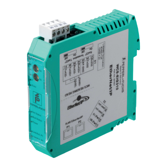
WCS-EIG310 Product Description Design of the Device Device Components Figure 2.2 Interface module overview RS-485 bus termination slide switch X1: RS-485 interface Mounting bracket X2: Connection for power supply X3: EtherNet/IP communication interface Front panel with rotary coding switch and LED indicator lights... - Page 8 WCS-EIG310 Product Description Front Panel WCS-EIG310 Modul Ethernet/IP Figure 2.3 Front panel overview WCS read head: LED status indicator and rotary coding switch Power: The "Power" LED lights up green: power supply is present. State: The "State" LED is green: Data is being exchanged with the WCS read heads. The four "Error No/Select ID"...
- Page 9 WCS-EIG310 Product Description LED ErrorNo/Select ID Error number Error description LED8 LED4 LED2 LED1 Reserved Hardware error EEPROM error Internal memory error Fieldbus hardware error or incorrect fieldbus ID Script error Reserved WCS read head communication, RS send buffer overflow...
- Page 10 WCS-EIG310 Product Description EtherNet/IP: LED status indicator Net Status: "Net Status" LED Interface state Flashes green/red Self-test Lights up green Connection present, data exchange is active Flashes green Waiting for a connection to be established Flashes red Connection has timed out...
-
Page 11: Installation
WCS-EIG310 Installation Installation Mounting Mounting the Modules The module is fastened to a DIN mounting rail with a width of 35 mm using a snap-on fixing method. Figure 3.1 Mounting Hook the module (1) onto the DIN mounting rail (2) from above and press it down until it snaps into place. -
Page 12: Electrical Connection
WCS-EIG310 Installation Electrical Connection Danger! Device damage due to incorrect installation Incorrect installation of cables and connection lines can endanger the function and the electri- cal safety of the device. • Observe the permissible core cross section of the conductor. - Page 13 WCS-EIG310 Installation Connecting the Power Supply Connect the operating voltage (10 VDC ... 30 VDC) to terminals 1 and 2 of the 4-pin plug X2 on the interface module. In addition, note the label on the module. The "Power" LED lights up green.
- Page 14 WCS-EIG310 Installation Preparing for Operation on RS-485 Interface For operation on an RS-485 interface, the terminals on connector X1 must be connected: Connect the read head to the terminal. Use the enclosed jumper to connect the terminals to each other...
-
Page 15: Dismounting
WCS-EIG310 Installation Dismounting Dismounting the modules Use a suitable slot-head screwdriver for dismounting the module. Disconnect all the supply and signal lines. Figure 3.4 Dismounting Insert the screwdriver (2) into the groove of the mounting bracket (3). Press the screwdriver (2) in the specified direction until the lock on the DIN mounting rail (4) opens, see figure. -
Page 16: Commissioning
Installation and commissioning must only be carried out by trained personnel in accor- dance with safety regulations. Components To commission the module, you will require the following components: • WCS-EIG310 interface module • EDS file (the EDS file can be obtained free of charge from our website www.pepperl- fuchs.com). •... -
Page 17: Connecting The Wcs Read Head
WCS-EIG310 Commissioning Connecting the WCS Read Head If you connect several WCS read heads to one interface module, the WCS read heads must have different addresses. This will allow the programmable logic controller to allocate the data to the correct WCS read heads. If you only connect one WCS read head to an interface mod- ule, this WCS read head always receives the address 0. - Page 18 WCS-EIG310 Commissioning Connecting the WCS Read Head Connect the voltage supply for the WCS read head to terminals 1 and 2 of the 4-pin connector X2 on the interface module. Connect the RS-485 data cable to the WCS read head on terminals 4 and 5 of connector X1.
-
Page 19: Connection To The Network
WCS-EIG310 Commissioning Connection to the Network The connection to EtherNet/IP is made via the two RJ45 EtherNet/IP P1 and P2 sockets on the underside of the interface module. The front socket is labeled P1 and the rear socket is labeled P2. -
Page 20: Setting The Ip Address And Subnet Screen
WCS-EIG310 Commissioning Setting the IP Address and Subnet Screen To set the device IP address, the subnet screen, and the gateway IP address, you need the WCS UGC_PF configuration tool. Downloading the Software Tool from the Internet The software tool can be downloaded from our website: www.pepperl-fuchs.com. - Page 21 WCS-EIG310 Commissioning 6. Write the amended configuration into the interface module by clicking "Download." The configuration has now been changed according to your requirements and saved in the non-volatile memory of the interface module. Setting Rotary Switches S4 and S5 Switch off the interface module.
-
Page 22: Network Settings
WCS-EIG310 Commissioning Network Settings The interface modul uses implicit messaging. Therefore, any position and speed data is mapped directly in the controller. The following figure shows the correct setting for integrating the interface module into the network. Parameters Value Input assembly... - Page 23 WCS-EIG310 Commissioning You have connected three readers to the interface module and want to use the velocity output. Enter the value 18 in both fields "Input Size" and "Output Size".
-
Page 24: Communication With Wcs Read Heads
WCS-EIG310 Communication with WCS read heads Communication with WCS read heads Request Byte for Read Heads Read head address Read head address Read head address Read head address F0=0: The read head sends the position data to the interface module. This standard function is automatically active after commissioning. - Page 25 WCS-EIG310 Communication with WCS read heads Address bits A1 and A0 Reader address Reader address 0 Reader address 1 Reader address 2 Reader address 3 Status bits Optical state OUT Description of WCS reader Current position value binary coded in P00...P18...
-
Page 26: Appendix
WCS-EIG310 Appendix Appendix Software Tool for RSLogix 5000, V15, and V17 This small tool divides the 4 or 6 byte long messages of each WCS read head into the position values, the speed values, and diagnostic information. Position and speed of WCS when using ... -
Page 27: Cable Routing In The Rs-485 Bus
WCS-EIG310 Appendix Cable Routing in the RS-485 Bus The data cables must always form an in-line connection between the first and the last node. This in-line connection must end with a terminator. The RS-485 terminators are integrated in the WCS readers and can be switched on and off with the interface module. - Page 28 WCS-EIG310 Appendix Reading head Reading head Interface or control (PLC) Figure 6.2 Connection of two reading heads, Version A • Version B: The interface module is located at the beginning of the data line; one WCS reader is located at the end of the data line. Both need the RS-485 terminator. The second WCS reader is connected to the line connection between the interface module and the first WCS reader through a short spur (length <1 m).
- Page 29 WCS-EIG310 Appendix Reading head Spur line (max. 1 m) Reading head Interface or control (PLC) Figure 6.3 Connection of two reading heads, Version B The wiring version used depends on which is best suited for the application. If three or four WCS readers are used on the same interface module, connect these using spurs as shown in variant B.
-
Page 30: Data Cable
WCS-EIG310 Appendix Data Cable A shielded data cable with twisted-pair cores is used for the electrical connection. Pep- perl+Fuchs can supply suitable preassembled M12 single-ended female cordsets () or field- attachable M12 female connectors and data cables. Data Cable WCS-DC* There are two types of data cable available: •... - Page 31 WCS-EIG310 Appendix Cable Length For the RS-485 data transfer path, a four-wire, shielded, twisted pair data cable must be used. One core pair is used for the supply voltage, and one pair for the RS-485 data connection. The maximum length of the cable depends on the capacitance of the data cable—core-core—for data transfer, and on the cross section of the cables for voltage supply to the read heads.
- Page 32 WCS-EIG310 Appendix Cable Overview The cable types listed below represent a selection of the types available from Pepperl+Fuchs. You can find additional cable types on our website. Note For customizable cables, observe the cable length restrictions specified by the interface specifications.
- Page 33 Pepperl+Fuchs Quality Download our latest policy here: www.pepperl-fuchs.com/quality www.pepperl-fuchs.com © Pepperl+Fuchs · Subject to modifications Printed in Germany / DOCT-6396...
Need help?
Do you have a question about the WCS-EIG310 and is the answer not in the manual?
Questions and answers