Table of Contents
Advertisement
Read the operating and
mounting instructions be-
fore commissioning.
Only specialised personnel
may perform work on the
automatic burner control system.
Never perform any work
when the control system is
live. This also applies if low-volt-
age components such as servo-
motors, display or communica-
tion components are replaced or
installed.
In case of fuse failure,
check the safety function
of the automatic burner control
system. Otherwise contact weld
caused by short-circuit may oc-
cur.
Only specialised personnel
may set operating param-
eters.
Only use the communica-
tion connection together
with components expressly ap-
proved for this purpose.
Perform the connection re-
lated to the correct phase
and the protective conductor con-
nection according to the terminal
diagram and check it before com-
missioning.
Warranty for the control
system expires on im-
proper handling of the electronic
system or due to incorrect stor-
age.
The data contained in these
instructions specify the au-
tomatic burner control system.
They do not imply any character-
istics.
If you do not follow these
instructions, danger to life
to the equipment may occur.
1 ... 112
Operating and mounting
instructions
Automatic burner control
system
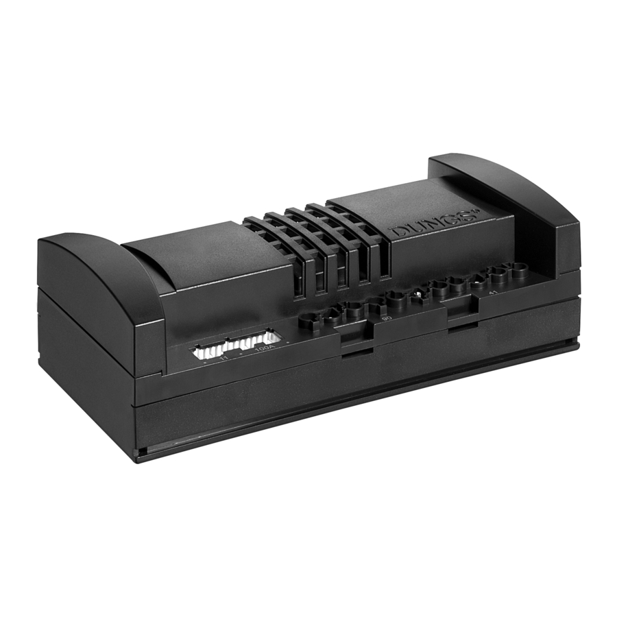
MPA22
Technical description
The MPA22 is a microprocessor-con-
trolled, automatic burner control sys-
tem with intermittent duty for control-
ling and monitoring two- and three
stage modulating blower burners with
a single servomotor, electronic modu-
lating blower burners with 2 servomo-
tors in combination with an electronic
control unit, and pneumatic modulat-
ing blower burners with 1 servomotor.
With integrated valve proving system
for operation as automatic gas burner
control system.
Accessories
Flame monitoring device
Servomotors
Display unit
Minimum display
eBUS interface
Mounting bracket
Coding plug
Order data
see Annex
Classification according to EN 298
FMCLJN, depending on programming
FMLLJN, depending on programming
Approvals for gas types
EU type test approval as per EU Gas
Appliance Directive.
MPA22
CE-0085AU316
Approvals for oil types
Register/type test number
MPA22
F185/99
Advertisement
Table of Contents

Subscribe to Our Youtube Channel
Related Manuals for Dungs MPA22


Summary of Contents for Dungs MPA22
- Page 1 Technical description Order data The MPA22 is a microprocessor-con- see Annex The data contained in these trolled, automatic burner control sys- instructions specify the au- tem with intermittent duty for control- Classification according to EN 298 tomatic burner control system.
-
Page 2: Table Of Contents
Contents Operating modes ............................... 10 Operating mode Gas firing, electronic modulation .......................... 11-12 Terminal diagram - Gas firing, electronic modulation ....................13 Terminal diagram - Gas firing, pneumatic modulation ..................14-15 Terminal diagram - Gas firing, pneumatic modulation ....................16 Operating mode - Oil firing, three stage ....................... - Page 3 The protective conductor connection for the burner is performed using the protective conductor cable with connector for the au- tomatic burner control system. Permanently tighten the connec- tion screw which connects the MPA22 and the protective con- ductor connection with the burner housing. 3 … 112 Weight approx.
- Page 4 Specifications Breaking capacities Designation Breaking capacity 230 VAC/4 A/cos ϕ = 1 Burner motor Total max. 10 A 230 VAC/4 A/cos ϕ = 1 Burner motor (endurance run) 230 VAC/3 A/cos ϕ = 1 Ignition transformer 230 VAC/2 A/cos ϕ = 1 Valve Y1 + status display 230 VAC/2 A/cos ϕ...
- Page 5 None No access, read only On the MPA22, the operator has read access only. If a password is not entered, only operating data request and fault unlock in case of fault are possible. When a password is entered, the Service personnel can activate the setting and the parameterisation mode in order to change the settings marked as SERVICE (see above) within the limits indicated.
- Page 6 Specifications Setpoints for the servomotor char- The following setpoints for the air motor and gas motor in each operating mode acteristics may only be changed in setup mode; they are not enabled until the settings for automatic burner operation have been completed. The setting values are to be recorded in the setup log after the burner has been set and should be kept in a safe place on the machine and in a suitable form.
- Page 7 Specifications Device specific counters, storage Contain general information which is retrievable via the display unit by the devices and data operator. Counters and storage devices Description As-delivered state Start-up counter deleted Operating hours counter stage 1 deleted Operating hours counter stage 2 deleted Operating hours counter stage 2 deleted...
- Page 8 Specifications Direction of rotation of the MPA22 can be parameterised so that the servomotors can rotate both anti- servomotors clockwise and clockwise in all operating modes. Two reference marks (A and B) can be used for the servomotor. Also, the reference point can be defined as 0°...
- Page 9 Specifications Dimensions Ø 4.5 arbitrary Installation position 9 … 112...
- Page 10 1 2 3 4 5 6 7 8 9 0 1 2 3 4 5 6 7 8 9 0 1 2 3 4 5 6 7 8 9 0 1 2 1 2 3 4 5 6 7 8 9 0 1 2 3 4 5 6 7 8 9 0 1 2 3 4 5 6 7 8 9 0 1 2 3 4 5 6 7 8 9 0 1 2 3 4 5 6 7 8 9 0 1 2 3 4 5 6 7 8 9 0 1 2 1 2 3 4 5 6 7 8 9 0 1 2 3 4 5 6 7 8 9 0 1 2 3 4 5 6 7 8 9 0 1 2 3 4 5 6 7 8 9 0 1 2 3 4 5 6 7 8 9 0 1 2 3 4 5 6 7 8 9 0 1 2 1 2 3 4 5 6 7 8 9 0 1 2 3 4 5 6 7 8 9 0 1 2 3 4 5 6 7 8 9 0 1 2 3 4 5 6 7 8 9 0 1 2 3 4 5 6 7 8 9 0 1 2 3 4 5 6 7 8 9 0 1 2 1 2 3 4 5 6 7 8 9 0 1 2 3 4 5 6 7 8 9 0 1 2 3 4 5 6 7 8 9 0...
-
Page 11: Operating Modes
Operating modes Gas modulating mode (electronic) with stepped motor to control the air and Operating modes of MPA22 gas volume. Gas modulating mode (pneumatic) with servomotor air damper control Oil firing, three stage with oil preheater and servomotor air damper control... -
Page 12: Operating Mode
+ and capacity - and thus regulates the capacity over the predefined characteristic curve in the range between bu and If the MPA22 has already been in service for 24 hours, a controlled shut-down is executed automatically. -
Page 13: Gas Firing, Electronic Modulation
Operating mode Gas firing, electronic modulation Response to faults If no flame is present after the startup safety period has elapsed, a safety shut- Gas firing, electronic modulation down takes place and the system executes a restart (if permitted). A fault lockout is triggered otherwise. -
Page 14: Terminal Diagram - Gas Firing, Electronic Modulation
230 VAC Fan motor 50 Hz Ignition transformer Output controller Safety ϑ circuit GW min. Pulse counter Pulse Air pressure Ionisation switch Remote unlocking device (only with Dungs display AM01) Actuator Actuator Display eBus gas flap air flap 14 … 112... - Page 15 P1 and dwells there for 8 s. The automatic burner control is now in the service position. If the MPA22 has already been in service for 24 hours, a controlled shut-down is executed automatically.
- Page 16 Operating mode Gas firing, pneumatic modulation Gas pressure switching Gas pressure switch GW_min is fitted upstream of the two gas valves of the Gas fail-safe program for gas Ratio control. burners with pneumatic modula- If a pressure sufficient to actuate gas pressure switch GW_min does not build tion up one second before the startup safety period commences, burner start-up is interrupted.
-
Page 17: Terminal Diagram Gas Firing, Pneumatic Modulation
50 Hz Ignition transformer Output controller Safety ϑ circuit GW min. Pulse counter Pulse GW VPS Air pressure Ionisation switch Remonte unlocking device (only with Dungs display AM01) Encoding Actuator Display eBus air flap plug, pneu- matic 17 … 112... -
Page 18: Operating Mode Oil Firing, Three Stage
Changeover to the next lower stage is implemented in the reverse order. Once a changeover has been initiated it is completed. If the MPA22 has already been in service for 24 hours, a controlled shut-down is executed automatically. If the heating request is cancelled, a controlled shut-down takes place. Valves Y1, Y2 and Y3 close and the blower runs on for the preset postventilation period. - Page 19 Operating mode Oil firing, three stage Response to faults If no flame is present after the startup safety period has elapsed, the burner Oil firing, three stage enters the non-variable fault state. If flame failure occurs while the burner is operating, a fault shut-down takes place and the system executes a restart.
-
Page 20: Terminal Diagram - Operating Mode - Oil Firing, Three Stage
230 VAC Blower 50 Hz motor Ignition 2. Stage transformer 3. Stage Safety ϑ sequence Oil switch min. Pulse counter Imp. Air pressure switch Remote unlock (with Dungs display AM01 only) Servomotor Display Coding plug eBus Air damper 20 … 112... -
Page 21: Integrated Valve Proving System, Electronic Modulation
Integrated valve proving system, electronic modu- lation The valve proving function can be enabled or disabled in parameterisation Valve test, gas burner mode. After a power failure or a fault unlock, the gas valves are always subjected to a leakage check before the burner is started. Otherwise, a leakage check is always performed after a controlled shut-down of the burner. -
Page 22: Time Diagram - Operating Mode - Gas Firing, Electronic Modulation
<24 1..240 1..240 1..240 0..100 <24 10..60s Time diagrams for MPA22 gas burner, electronic modulation Definitions of individual states Start-up tests Processor and program memory test/move servomotor to reference point State 01 Start-up decision (heating request issued) State 02 Idle state check, blower... - Page 23 Time diagram Gas firing, electronic modulation Start without flame after start-up safety period 1 restart permitted, valve proving system inactive State number Start-up tests 09 Start-up tests Display TEST TEST L 9 F xxh Closed-loop Input control sequence Input GW max Input GW min Input...
-
Page 24: Time Diagram - Operating Mode - Gas Firing, Pneumatic Modulation
<24 1..240 1..240 1..240 0..100 <24 10..60s Time diagram for MPA22 gas burner, pneumatic modulation Definitions of individual states Start-up tests Processor and program memory test/move servomotor to reference point State 01 Start-up decision (heating request issued) State 02 Idle state check, blower... - Page 25 Time diagram Gas firing, pneumatic modulation Start without flame after start-up safety period 1 restart permitted, valve proving system inactive State number Start-up tests Start-up tests Display TEST TEST F xxh Closed-loop Input control sequence Input GW max Input GW min Air pressure switch Input Flame...
-
Page 26: Time Diagram Oil Firing, Three Stage
2..5 1..60 8..30 <24 1..240 0..100 <24 Time diagram for MPA22 oil firing, three stage Definitions of individual states Start-up tests Processor and program memory test/move servomotor to reference point State 01 Start-up decision (heating request issued) State 02 Idle state check, blower... -
Page 27: Time Diagram - Oil Firing, Three Stage
Time diagram Oil firing, three stage Start without flame after start-up safety period State number Start-up tests Display TEST F xxh Closed-loop Input control sequence Input ÖW max Input ÖW min Input Air pressure switch Input Flame Input GW VPS Output Blower motor Output... -
Page 28: Explanation Display
Explanation Display Display elements The MPA22 is controlled by means of 5 buttons on the touch-sensitive display. The individual parameters are displayed on the liquid-crystal display. Lights up when the Lights up when the gas-flow control air-flow control Liquid-crystal Symbols for... -
Page 29: Display Functions
Display functions Setup mode Gas, electronic modulation Gas, pneumatic modulation Oil, three stage Display functions Operating mode Information mode Service mode Parameterisation mode Parameterisation mode is password-protected. Error indication System error messages Error messages 29 … 112... -
Page 30: Relationships Between The Individual Display Modes
Relationships between the individual display modes Switch on line voltage RESET O.K.? No ID Password entry Press approx. 0.5 s Password correct? Configuration Load Fault interlock? Error Display during start tests 30 … 112... -
Page 31: Relationships Between The Individual Display Modes
Relationships between the individual display modes 31 … 112... -
Page 32: Display During Standby
Display during standby The automatic burner-control system is on standby following a controlled shut- down. No pending request for heat. The automatic burner-control system is on standby because line voltage is too low. The automatic burner-control system is on standby because the safety chain is interrupted at input GWmax. -
Page 33: Display When A Password Is Entered In Parameterisation Or Setup Mode
Display when a password is entered in parameteri- zation or setup mode Operating display Press combination of buttons which corresponds to destination Select active position in display Go left Decrement active position in display Increment active position Go right in display Active position in display flashes. -
Page 34: Display When The Basic Configuration Is Entered
Display when the basic configuration is entered No ID Select active position in display Go left Decrement active position in display Increment active position Go right in display Active position in display flashes. Goes low when you press "+" or "-". approx. - Page 35 Display when the basic configuration is entered Press buttons 1 and 2 to confirm the software version. approx. 2 seconds Setting for the air motor's start point. Inkrement value Valid settings are: Ref. A 0° Ref. A 90° Ref. B 90°...
-
Page 36: Commissioning Setup Mode
The values entered beforehand are retained, on condition that they pass the plausibility check which takes place on startup. You must enter a password before you can set the parameters of the MPA22 Setup instructions, setup proce- automatic burner-control system. -
Page 37: Commissioning Main Parameters
Commissioning Main parameters Begin by setting the main para- The sequence for the main parameters is invariable, because they are inter- meters for the individual operat- related by certain dependencies and limit values and these limits are constantly ing modes checked and rechecked during the setup procedure. -
Page 38: Setup Mode Gas Firing, Electronic Modulation
Setup mode Gas firing, electronic modulation The burner must be in standby The controller automatically goes to standby status if the automatic burner- status, otherwise you cannot control system has not been programmed. In the unprogrammed state, the access the setup mode automatic burner-control system remains on standby. - Page 39 Setup mode Gas firing, electronic modulation Temperature con- Display if parameters Display in standby if not troller switched ON already set programmed Unprogrammed? Password entry Password entry Password Password correct? correct? Switch on temperature Start, set main GWmax controller and close con- parameters "ON"...
- Page 40 Setup mode Gas firing, electronic modulation The settings for main parameters P9, P1 and P0 are burner-specific and Set main parameters P9, P1, P0 must be quoted by the manufacturer. Set characteristic point P9 ° max. 90.0 Servo drive, gas Servo drive, air °...
- Page 41 Setup mode Gas firing, electronic modulation Set ignition point P0 max. P0 ≤ P1 + 25.5 ° Servo drive, gas Servo drive, air min. P0 ≥ P1 - 25.5 ° P0 ≥ 00.0 ° Prompt for burner start so that points P2 - P8 can be set.
- Page 42 Setup mode Gas firing, electronic modulation Burner start position Startup see start phase Gas firing, modulated "P" also lights up When burner is lit: If start is successful, the burner 1.Set the gas-pressure regulator remains in the ignition position. Burner fired in ignition position to the value specified in the If flame does not stabilize, repeat the...
- Page 43 Setup mode Gas firing, electronic modulation Servo drive, air Servo drive, gas Timeout Restart approx. 30 min. Set characteristic point P1 ° max. P0 + 25.5 P1 ≤ P2 min. P1 ≥ 00.0 ° ° P0 - 25.5 P9 set? 43 …...
- Page 44 Setup mode Gas firing, electronic modulation Servo drive, gas Servo drive, air Timeout Restart approx. 30 min. Set characteristic point P2 ° max. P1 + 25.5 P2 ≤ P3 min. P1 P9 set? 44 … 112...
- Page 45 Setup mode Gas firing, electronic modulation Servo drive, gas Servo drive, air Timeout Restart approx. 30 min. Set characteristic point P3 ° max. P2 + 25.5 P3 ≤ P4 min. P2 P9 set? 45 … 112...
- Page 46 Setup mode Gas firing, electronic modulation Servo drive, air Servo drive, gas Timeout Restart approx. 30 min. Set characteristic point P4 ° max. P3 + 25.5 P4 ≤ P5 min. P3 P9 set? 46 … 112...
- Page 47 Setup mode Gas firing, electronic modulation Servo drive, gas Servo drive, air Timeout Restart approx. 30 min. Set characteristic point P5 ° max. P4 + 25.5 P5 ≤ P6 min. P4 P9 set? 47 … 112...
- Page 48 Setup mode Gas firing, electronic modulation Servo drive, gas Servo drive, air Timeout Restart approx. 30 min. Set characteristic point P6 ° max. P5 + 25.5 P6 ≤ P7 min. P5 P9 set? 48 … 112...
- Page 49 Setup mode Gas firing, electronic modulation Servo drive, gas Servo drive, air Timeout Restart approx. 30 min. Set characteristic point P7 ° max. P6 + 25.5 P7 ≤ P8 min. P6 P9 set? 49 … 112...
- Page 50 Setup mode Gas firing, electronic modulation Servo drive, gas Servo drive, air Timeout Restart approx. 30 min. Set characteristic point P8 ° max. P7 + 25.5 P8 ≤ P9 min. P7 P9 set? 50 … 112...
-
Page 51: Setup Mode - Gas Firing, Electronic Modulation
Setup mode Gas firing, electronic modulation Servo drive, gas Servo drive, air Timeout Restart approx. 30 min. Set characteristic point P9 Set minimum burner load ° max. P8 +25.5 max. bo P9 ≤ 90.0 ° min. P8 Set minimum burner load Servo drive, air Pmin. -
Page 52: Setup Mode Gas Firing, Pneumatic Modulation
Setup mode Gas firing, pneumatic modulation The burner must be in standby The controller automatically goes to standby status if the automatic burner- status, otherwise you cannot control system has not been programmed. In the unprogrammed state, the access the setup mode automatic burner-control system remains on standby. - Page 53 Setup mode Gas firing, pneumatic modulation Display if parameters Display in standby if not already set programmed Unprogrammed? Password entry Password entry Password Password correct? correct? Switch on temperature Start, set main GWmax controller and close con- parameters P9, "ON" tact GWmax P1, P0 Preset working...
- Page 54 Setup mode Gas firing, pneumatic modulation The settings for the working points are burner-specific and must be quoted by the manufacturer. Preset working points max. 90.0° P9 = Maximum point Servo drive, air on characteristic for high load min. 00.0° max.
- Page 55 Setup mode Gas firing, pneumatic modulation If start is successful, the burner Burner start remains in the ignition position. position If flame does not stabilize, repeat the procedure with new ignition point P0. Startup see start phase "Gas firing, pneumatic modulation"...
-
Page 56: Setup Mode - Gas Firing, Pneumatic Modulation
Setup mode Gas firing, pneumatic modulation Press "1" and "2" simultaneously to exit the setup mode. Generate CRC check- sum from settings. Set flag to "programmed" End of setup mode Gas firing pneumatic modulation 56 … 112... -
Page 57: Setup Mode Oil Firing, Three Stage
Setup mode Oil firing, three stage The burner must be in standby The controller automatically goes to standby status if the automatic burner- status, otherwise you cannot control system has not been programmed. In the unprogrammed state, the access the setup mode automatic burner-control system remains on standby. - Page 58 Setup mode Oil firing, three stage Display if parameters Display in standby if already set not programmed Unprogrammed? Password entry Password entry Password Password correct? correct? Switch on temperature Start, preset work- controller and close ing points GWmax "ON" contact GWmax Preset working Burner start position...
- Page 59 Setup mode Oil firing, three stage Preset working points max. 90.0° P9 = Stage 3 Servo drive, air min. 00.0° max. P9 - 0.1° P3 = Stufe 2 Servo drive, air min. 00.0° max. P3 - 0.1° P1 = Stage 1 Servo drive, air min.
- Page 60 Setup mode Oil firing, three stage max. P1 P0 = Ignition Servo drive, air point min. 00.0° max. P3 P2 = Change- Servo drive, air over point min. P1 + 0.1° between stages 1 and 2 max. P9 P4 = Change- Servo drive, air over point min.
- Page 61 Setup mode Oil firing, three stage Prompt for burner start Contact GWmax. closed to start the burner: temperature con- GWmax "ON" troller must be closed. Burner start position If start is successful, the burner Startup see start remains in the ignition position. phase "Oil firing, three-stage"...
- Page 62 Setup mode Oil firing, three stage Working point 1 max. P2 - 0.1° Set stage 1 Servo drive, air min. 00.0° Stage 1 Timeout achieved RESTART approx. 30 min. Transition to stage 2 Stage 2 achieved Working point P3 max. P4 - 0.1° Set stage 2 Servo drive, air min.
- Page 63 Setup mode Oil firing, three stage Working point P3 max. P4 - 0.1° Set stage 2 Servo drive, air min. P2 Stage 2 Timeout achieved RESTART approx. 30 min. Transition to stage 3 Stage 3 achieved Working point P9 max. 90.0° Set stage 3 Servo drive, air min.
- Page 64 Setup mode Oil firing, three stage Set changeover max. P3 point P2 Servo drive, air min. P1 + 0.1° Timeout RESTART approx. 30 min. Set changeover max. P9 point P4 Servo drive, air min. P3 +0.1° Timeout RESTART approx. 30 min. Press "1"...
-
Page 65: Gas Firing, Electronic Modulation And Gas Firing, Pneumatic Modulation
Display in operating mode Gas firing, electronic modulation Gas firing, pneumatic modulation Display in operating mode, gas firing with electronic modulation and gas firing with pneumatic modulation. If setup mode is activated, the "P" symbol also appears in the start phase. 65 …... -
Page 66: Display In Operating Mode
Display in operating mode Gas firing, electronic modulation Gas firing, pneumatic modulation After line-voltage interruption or if a request for heat was pending in Restart standby mode. Internal tests such as ROM test, CPU test, RAM test, etc. Check servo drive for air and go to reference point. -
Page 67: Display In Operating Mode
Display in operating mode Gas firing, electronic modulation Gas firing, pneumatic modulation Safety chain and temperature con- troller are both polled. Process con- tinues if both are closed. Otherwise, go to standby =“OFF“. Move servo drive for air to character- istic point P9. -
Page 68: Display In Operating Mode
Display in operating mode Gas firing, electronic modulation Gas firing, pneumatic modulation Move servo drive for air to ignition point P0. If valve test switched on but not yet performed Pre-ignition Safety period without flame message Safety period with flame message Stabilization time At ignition point P0 Go to characteristic point P1 from... -
Page 69: Display In Operating Mode
Display in operating mode Gas firing, electronic modulation Gas firing, pneumatic modulation Operating position. Shows position of the servo drive for air in XX.X° Operating position. Increase output or go to minimum out- put point. Operating position. Reduce output. Valve test after fault If valve test off Controlled shutdown Valve test, phase 1 (emptying). -
Page 70: Display In Operating Mode
Display in operating mode Gas firing, electronic modulation Gas firing, pneumatic modulation Valve test, phase 4 (test time V2). When the post-purging time expires, the brackets G or brackets L/A symbols and the Down arrow might also light up while the servo drive for air is moving to the standby position. -
Page 71: Display In Operating Mode Oil Firing, Three Stage
Display in operating mode Oil firing, three stage Display in operating mode, oil firing, three stage. If setup mode is activated, the "P" symbol also appears in the start phase. 71 … 112... - Page 72 Display in operating mode Oil firing, three stage After line-voltage interruption or if a request for heat was pending in Restart standby mode. Internal tests such as ROM test, CPU test, RAM test, etc. Check servo drive for air and go to reference point.
-
Page 73: Display In Operating Mode
Display in operating mode Oil firing, three stage If servo drive for air is at characteristic point P9 and the air-pressure monitor is not in idle position. Watchdog loads. Pre-vent Purging time countdown in seconds. Watchdog pulls up and latches. Pre-vent Purging time countdown in seconds. -
Page 74: Display In Operating Mode
Display in operating mode Oil firing, three stage Safety period without flame message Safety period with flame message Stabilization time Go to characteristic point P1 from ignition point P0 Wait before operating position at Stage 1 Operation Stage 1 74 … 112... -
Page 75: Display In Operating Mode
Display in operating mode Oil firing, three stage Operation Changeover point between stages 1 and 2 Operation Stage 2 Operation Changeover point between stages 2 and 3 Operation Stage 3 75 … 112... -
Page 76: Display In Operating Mode „Oil Firing, Three Stage
Display in operating mode Oil firing, three stage Operating position. Changeover point between stages 3 and 2 Operating position. Changeover point between stages 2 and 1 Post-venting with blower in operation. Post-venting ended. The blower is off. The servo drive for air goes to the standby position. -
Page 77: Display In Information Mode
Display in information mode Gas firing, electronic modulation Gas firing, pneumatic modulation Oil firing, three stage The information-mode display can be accessed only from the operating-mode display. It can be called up irrespective of burner status and provides infor- mation on: Current counts for •... -
Page 78: Display In Information Mode
Display in information mode Gas firing, electronic modulation Gas firing, pneumatic modulation Oil firing, three stage Operating display Press for approx. 0.5 s until the "i" symbol is displayed. Release button. Information display Total fuel consumption in liters of oil or cubic meters of gas. -
Page 79: Display In Information Mode
Display in information mode Gas firing, electronic modulation Gas firing, pneumatic modulation Oil firing, three stage Gas burners only Total operating hours in stage 2 for oil- fired burners. Timeout approx. 20 s approx. 0.2 s Total operating hours in stage 3 for oil- fired burners. -
Page 80: Display In Information Mode
Display in information mode Gas firing, electronic modulation Gas firing, pneumatic modulation Oil firing, three stage approx. 0.2 s Date of compilation of the software. Timeout approx. 20 s approx. 0.2 s Automatic controller's serial number. Timeout approx. 20 s approx. -
Page 81: Display In Service Mode Gas Firing, Electronic Modulation
Display in service mode Gas firing, electronic modulation The service-mode display can be The service display can be called irrespective of the burner status and provides accessed only from the operat- information on the characteristic stored in the EEPROM. The following data ing-mode display. -
Page 82: Display In Service Mode
Display in service mode Gas firing, electronic modulation Operating display Press for approx. 0.5 s until the "Wrench" symbol is displayed. Release button. The "i" symbol is dis- played for approx. 1.5 s beforehand. Service display Values of ignition point P0 Timeout approx. - Page 83 Display in service mode Gas firing, electronic modulation Values of characteristic point P2 Timeout approx. 20 s approx. 0.2 s Values of characteristic point P3 Timeout approx. 20 s approx. 0.2 s Values of characteristic point P4 Timeout approx. 20 s approx.
-
Page 84: Gas Firing, Electronic Modulation
Display in service mode Gas firing, electronic modulation Values of characteristic point P6 Timeout approx. 20 s approx. 0.2 s Values of characteristic point P7 Timeout approx. 20 s approx. 0.2 s Values of characteristic point P8 Timeout approx. 20 s approx. -
Page 85: Display In Service Mode
Display in service mode Gas firing, electronic modulation Timeout Most recent error in hexadecimal nota- approx. 20 s tion. Extra error information by When the "+" button pressing the "+" button is released approx. 0.2 s Extra error information Left: Extra error code Right: No. -
Page 86: Display In Service Mode
Display in service mode Gas firing, electronic modulation Third last error in hexadecimal nota- tion. Timeout approx. 20 s approx. 0.2 s Fourth last error in hexadecimal nota- tion. Timeout approx. 20 s approx. 0.2 s Fifth last error in hexadecimal notation. Timeout approx. -
Page 87: Display In Service Mode
Display in service mode Gas firing, electronic modulation Testing time, valve Y2 Timeout approx. 20 s approx. 0.2 s Testing time, valve Y3 Timeout approx. 20 s approx. 0.2 s Flame quality indication 0 - 4 0 = no flame Timeout approx. -
Page 88: Display In Service Mode
Display in service mode Gas firing, electronic modulation Mode indicator: integrated valve test- ing system is ON or OFF. Timeout approx. 20 s approx. 0.2 s Lower limit of modulation range Timeout approx. 20 s approx. 0.2 s Upper limit of modulation range Timeout approx. -
Page 89: Display In Service Mode Gas Firing, Pneumatic Modulation
Display in service mode Gas firing, pneumatic modulation The service-mode display can be The service display can be called irrespective of the burner status and provides accessed only from the operat- information on the characteristic stored in the EEPROM. ing-mode display. The following data are displayed: - The characteristic points P0, P1 and P9 - The last 6 error messages... -
Page 90: Display In Service Mode
Display in service mode Gas firing, pneumatic modulation Operating display Press for approx. 0.5 s until the "Wrench" symbol is displayed. approx. 0.2 s Release button. The "i" symbol is dis- played for approx. 1.5 s beforehand. Service display Value of ignition point P0 for gas burner with pneumatic modulation. -
Page 91: Gas Firing, Pneumatic Modulation
Display in service mode Gas firing, pneumatic modulation Timeout approx. 20 s Most recent error in hexadecimal nota- tion. Extra error information by When the "+" button pressing the "+" button is released approx. 0.2 s Extra error information Left: Extra error code Right: No. - Page 92 Display in service mode Gas firing, pneumatic modulation Fifth last error in hexadecimal notation. Timeout approx. 20 s approx. 0.2 s Sixth last error in hexadecimal nota- tion. Timeout approx. 20 s approx. 0.2 s Testing time, valve Y2 Timeout approx.
-
Page 93: Display In Service Mode
Display in service mode Gas firing, pneumatic modulation Flame quality indication 0 - 4 0 = no flame Timeout approx. 20 s approx. 0.2 s The eBUS address of this automatic controller Timeout approx. 20 s approx. 0.2 s Mode indicator: integrated valve testing system is ON or OFF. - Page 94 Display in service mode Oil firing, three stage The service-mode display can be The service display can be called irrespective of the burner status and provides accessed only from the operat- information on the characteristic stored in the EEPROM. ing-mode display. The following data are displayed: - The characteristic points P0, P1, P3 and P9 - The changeover points P2, P4...
-
Page 95: Display In Service Mode
Display in service mode Oil firing, three stage Operating display Press for approx. 0.5 s until the "Wrench" symbol is displayed. Release button. The "i" symbol is dis- approx. 0.2 s played for approx. 1.5 s beforehand. Service display Value of ignition point P0 for oil burner, three-stage. -
Page 96: Display In Service Mode
Display in service mode Oil firing, three stage Value of working point, stage 2 (P3) for oil burner, three-stage. Timeout approx. 20 s approx. 0.2 s Value of changeover point P4 for changeover between stage 2 and stage 3 for oil burner, three-stage. Timeout approx. -
Page 97: Display In Service Mode
Display in service mode Oil firing, three stage Timeout Second last error in hexadecimal nota- approx. 20 s tion. Extra error information by pressing the "+" button When the "+" button approx. 0.2 s is released Extra error information Left: Extra error code Right: No. -
Page 98: Display In Service Mode
Display in service mode Oil firing, three stage Sixth last error in hexadecimal nota- tion. Timeout approx. 20 s approx. 0.2 s Flame quality indication 0 - 4 0 = no flame Timeout approx. 20 s approx. 0.2 s The eBUS address of this automatic controller Timeout approx. -
Page 99: Display In Service Mode
Display in service mode Oil firing, three stage Status indicator: monitor function active or inactive active = ON inactive = OFF Timeout ca. 20 s ca. 0,2 s Controller address of this automatic controller Timeout ca. 20 s ca. 0,2 s zurück zur zurück zur Betriebsanzeige... -
Page 100: Gas Firing, Electronic Modulation; Gas Firing, Pneumatic Modulation And Oil Firing, Three Stage
Display in parameteriza- tion mode Gas firing, electronic modulation Gas firing, pneumatic modulation Oil firing, three stage The parameterisation-mode dis- Parameterisation mode can be accessed only from the operating-mode display play can be accessed only from when the controller is on standby ("OFF"). Parameterisation mode is used to the operating-mode display in view important operating parameters and adjust the settings by means of the standby status. -
Page 101: Gas Firing, Electronic Modulation; Gas Firing, Pneumatic Modulation And Oil Firing, Three Stage
Display in parameteriza- tion mode Gas firing, electronic modulation Gas firing, pneumatic modulation Oil firing, three stage Operating display Press for approx. 2 s Password entry approx. 0.2 s Password correct? Parameterization mode 101 … 112... -
Page 102: Gas Firing, Electronic Modulation; Gas Firing, Pneumatic Modulation And Oil Firing, Three Stage
Display in parameteriza- tion mode Gas firing, electronic modulation Gas firing, pneumatic modulation Oil firing, three stage The eBUS communication address. Possible values are 03H, 13H, 33H, 73H, F3H Timeout approx. 20 s Timeout approx. 20 s The changed address is not stored until you advance the program or exit approx. - Page 103 Display in parameteriza- tion mode Gas firing, electronic modulation Gas firing, pneumatic modulation Oil firing, three stage Wait in minutes Permissible range 0 - 100 min. Press button and release = one Timeout increment approx. 20 s (1 s). Press and hold down = incre- ments slowly for 2.5 s, then more rapidly.
- Page 104 Display in parameteriza- tion mode Gas firing, electronic modulation Gas firing, pneumatic modulation Oil firing, three stage Air-flow control flap position in standby. Variable in the range 0 - 25.5°. Timeout Strike key = 1 step approx. 20 s Hold down key = 25 steps slow counting followed by high-speed counting.
- Page 105 Display in parameteriza- tion mode Gas firing, electronic modulation Gas firing, pneumatic modulation Oil firing, three stage Oil burner no valve test system Switch position of the valve testing system Valve testing system activated = ON Timeout Valve testing system deactivated = approx.
- Page 106 Display in parameteriza- tion mode Gas firing, electronic modulation Gas firing, pneumatic modulation Oil firing, three stage Specify test time for valve Y3 Permissible range: 1 - 240 Timeout Strike key = 1 step approx. 20 s Hold down key = 25 steps slow counting followed by high-speed counting.
- Page 107 Display in parameteriza- tion mode Gas firing, electronic modulation Gas firing, pneumatic modulation Oil firing, three stage Specify control address of system. The following addresses are possible: 10H, 17H, 30H, 37H, 70H, 77H, F0H, Timeout approx. 20 s Timeout approx. 20 s The changed address is not stored approx.
-
Page 108: Error Indication
Error indication Gas firing, electronic modulation Gas firing, pneumatic modulation Oil firing, three stage Error mode Error mode overwrites all other display modes. Error mode is not active unless a error is detected. Error indication The following appears on the display: •... - Page 109 Error indication Gas firing, electronic modulation Gas firing, pneumatic modulation Oil firing, three stage Error Reset by pressing the "Enter" Error code button for approx. 0.2 - 0.5 s. flashes When the "+" button is released Press "+" to view extra Restart error code Extra error information...
-
Page 110: System Error Messages
Error messages Code Meaning Internal device fault Internal device fault Internal device fault Internal device fault Internal device fault Internal device fault Internal device fault Internal device fault Internal device fault Internal device fault Internal device fault Air pressure switch is not in "off" position Air pressure switch failure Gas pressure switch failure No flame after safety period elapses... - Page 111 Error messages Code Meaning Safety circuit interrupted Y2 found to be leaky during leak test Y3 found to be leaky during leak test Internal device fault Internal device fault Internal device fault Internal device fault Internal device fault Internal device fault Internal device fault Internal device fault Internal device fault...
- Page 112 Error messages Code Meaning Internal device fault Internal device fault Internal device fault Internal device fault Air servomotor, incorrect acknowledgement (check cable and plug, servomotor and air damper mechanism) Gas servomotor, incorrect acknowledgement (check cable and plug, servomotor and gas damper mechanism) Air servomotor position out of tolerance (check cable and plug, servomotor and air damper mechanism) Gas servomotor position out of tolerance (check cable and plug,...
Need help?
Do you have a question about the MPA22 and is the answer not in the manual?
Questions and answers