
Related Manuals for schmersal EFAS CAM Module


Summary of Contents for schmersal EFAS CAM Module
- Page 1 Instruction Manual Instruction Manual Schmersal EFAS CAM Module DOC_MAN_MEC_EFAS-CAM_#SEN_#AIN_#V1 Seite 1 von 56 Version: 2018 / 02...
-
Page 2: Table Of Contents
Ports ..............................15 3.2.1 General information .......................... 15 3.2.2 Connector for power supply and I/O ....................15 3.2.3 CAN connector ..........................17 4 EFAS CAM Module ............................18 4.1.1 Supply voltage ..........................18 4.1.2 Status LEDs ............................. 18 4.1.3 Function ............................20 5 Software................................. - Page 3 Table of Contents 6.2.1 Info ..............................30 6.2.2 Exit ..............................30 Project ..............................31 6.3.1 new ..............................31 6.3.2 open ..............................31 6.3.3 save ..............................32 6.3.4 save as ............................32 6.3.5 Settings ............................32 Control ..............................35 6.4.1 Dead-Times (Control/Dead-Times) ....................35 6.4.2 Speed Change Scale (Control/Speed-Change-Scale)..............
-
Page 4: Preface
- on whatever grounds - are excluded, except in instances of deliberate intent or gross negligence on our part. 1.2.2 Terms of Delivery The general conditions of sales and service of K.A. Schmersal GmbH & Co. KG shall apply. 1.2.3 Copyright © K.A. Schmersal GmbH & Co. KG. -
Page 5: Warranty
Preface 1.2.4 Warranty Warranty is subject to the provisions of the conditions of sale of K.A. Schmersal GmbH & Co. KG or any contractual agreements between the parties. 1.3 Reliability, Safety 1.3.1 Applicability For reasons of personal safety and to avoid material damages when working with or handling this product, you are advised to take heed of the notes and information contained in this instruction manual. -
Page 6: Hazard And Other Warnings
Preface 1.3.5 Hazard and Other Warnings Despite the actions described in section 1.3.3, the occurrence of faults or errors in electronic control units - even if most highly improbable - must be taken into consideration. Please pay particular attention to the additional notices which we have marked by symbols throughout this instruction manual. -
Page 7: Safety
This applies to section 8 (Admissible deviations when working on parts) in particular. Repairs must be carried out by specially trained Schmersal staff only (usually in the main factory in Wuppertal). Warranty expires in every other case. ... -
Page 8: Electromagnetic Compatibility
Preface 1.3.8 Electromagnetic Compatibility Definition Electromagnetic compatibility is the ability of a device to function satisfactorily in its electromagnetic environment without itself causing any electromagnetic interference that would be intolerable to other devices in this environment . Of all known phenomena of electromagnetic noise, only a certain range occurs at the location of a given device. - Page 9 Preface Location of Installation Ensure that temperatures, contaminations, impact, vibration or electromagnetic interference are no impediment to the installation. Temperature Consider heat sources such as general heating of rooms, sunlight, heat accumulation in assembly rooms or control cabinets. Contamination Use suitable casings to avoid possible negative influences due to humidity, corrosive gas, liquid or conducting dust.
-
Page 10: Introduction
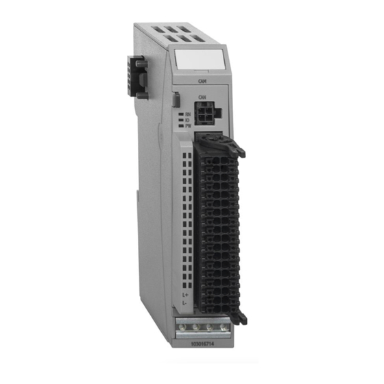
Paper or foil feeding Packaging machines Figure 1: EFAS CAM Module 2.1 Working principle of cam control units When developing the electronic cam control unit, we referred to the working principle of mechanical cam control units in order to keep understanding the method of operation and programming simple. -
Page 11: Position Detection
Introduction 2.1.3 Position detection An incremental encoder picks up the current machine position. Incremental encoders provide the angular momentum signals A and B. Changes in position are identified by counting the momentum signals. Checking the 180° offset of signals A and B allows you to establish the sense of rotation. Since the absolute position is unknown when the system turns on, each incremental encoder needs to be referenced. -
Page 12: Hardware
CAM Control 3 Hardware 3.1 Mechanical design The picture below illustrates the basic layout of the EFAS modules: Unlock button Label clip Grip Signal state indicators (LEDs) Status LEDs Shield-to-housing Slot for spring- mount connector assisted combi plug Module lock and E- Ventilation slots DIN rail mount and functional earth... -
Page 13: Installation
CAM Control In special cases you may attach the earth wire straight to the module. Attach cable shield here M3x5 bolt connection Figure 3: Aluminium profile NOTE Earth wires should be short and have a large surface (copper mesh). Refer to https://de.wikipedia.org/wiki/ground_(electronics) or a similar source for further details Installation... - Page 14 CAM Control Order of Modules in Multi EFAS Systems NOTE In order to ensure that the entire EFAS system works properly, arrange the EFAS modules by their specific E-bus load, placing the modules with the highest E-bus load immediately next to the head module (bus coupler or controller).
-
Page 15: Ports
CAM Control 3.2 Ports 3.2.1 General information The spring-assisted PUSH-IN connector allows you to quickly attach the wires by direct insertion without any tools. Just insert the connector sleeve end of the stripped solid or fine wire in the correct opening. Wires: 320V / 13.4 A / 0.14 - 1.5 mm²... - Page 16 CAM Control IO connector, left row Pin Signal Explanation DO1.0 Digital output 1.0 (track 9) DO1.1 Digital output 1.1 (track 10) DO1.2 Digital output 1.2 (track 11) DO1.3 Digital output 1.3 (track 12) DO1.4 Digital output 1.4 (track 13) DO1.5 Digital output 1.5 (track 14) DO1.6 Digital output 1.6 (track 15)
-
Page 17: Can Connector
CAM Control 3.2.3 CAN connector The CAN bus connects to the front of the module by means of a 4-pole Molex Micro-Fit Connector 3.0 Connector (supplier: Farnell) 43025-0400: female Micro FIT 3.0 43030-0010: crimp socket PK100 MOLEX-79516-1043-MICRO-PASS 4WAY CABLE ASSEMBLY 3M CAN_ CAN_ CAN_... -
Page 18: Efas Cam Module
CAM Control 4 EFAS CAM Module Figure 9: Connection of encoder, inputs, outputs and supply voltages Figure 10: Front view 4.1.1 Supply voltage Power supply to module I/Os 24 VDC -20%+25% L- 0 V 4.1.2 Status LEDs "Run" LED The "Run" LED indicates the state of the EtherCAT ASICs. - Page 19 CAM Control NOTE The output drivers have a thermal fuse to automatically turn off any short-circuited outputs. In case the short circuit prevails, the outputs are allowed to cool down to be turned back on until the thermal fuse blows again. "Power"...
-
Page 20: Function
CAM Control 4.1.3 Function The CAM Control module features 24 digital outputs used for mapping cam tracks. Run the "EFAS CAM-Creator" to write the cam program and save it on the fail-safe CAM Control module memory. The CAM Control module supports the following operating options: ... - Page 21 CAM Control 4.1.3.2 Output variables Variable Data type Explanation Selects the cam program Control1 USINT (currently not implemented.) Control2 USINT Control bits PositionSet UINT Sets the position in slave mode SpeedSet UINT Sets the velocity in slave mode Bit no. Explanation if TRUE Reset Error (if 1) Control2 Reference the position (0->1)
-
Page 22: Software
Software 5 Software Run the EFAS CAM-Creator to write your cam programs and program the EFAS CAM Module This section describes how to start the EFAS CAM-Creator. 5.1 Download All necessary programs, equipment descriptions and instructions are available in our download area: http://www.schmersal.com/net/efas... -
Page 23: Start/Exit
Software 5.3 Start/Exit EFAS CAM-Creator starts by running EFASCAM.exe. The last project you used will be loaded. DOC_MAN_MEC_EFAS-CAM_#SEN_#AIN_#V1 Seite 23 von 56 Version: 2018 / 02... -
Page 24: Can Usb Driver
Software 5.4 CAN USB driver You will need drivers to operate the CAN to USB adapter supplied by Lawicel. We recommend proceeding as follows: Download the current drivers (e.g. CDM_2.08.14_CANUSB.zip) from http://www.can232.com make a note of the directory that contains the unzipped drivers. ... - Page 25 Software Browse to the folder that you unzipped the downloaded drivers to after, then click on OK. Click on "Next" to start the installation process. Skip any security prompts that may appear. You will see the following message shortly after the end of the installation. DOC_MAN_MEC_EFAS-CAM_#SEN_#AIN_#V1 Seite 25 von 56 Version: 2018 / 02...
- Page 26 Software You can now establish an online link between EFAS CAM-Creator and the EFAS CAM Module via the CAN to USB adapter. DOC_MAN_MEC_EFAS-CAM_#SEN_#AIN_#V1 Seite 26 von 56 Version: 2018 / 02...
-
Page 27: Efas Cam-Creator
EFAS CAM-Creator 6 EFAS CAM-Creator This section describes how to operate the EFAS CAM Creator. 6.1 Cam programming Once the application is up and running, you will see a table of cam programs on the left and the associated diagram - the CAM array - on the right-hand side of the screen. 6.1.1 Editing the cams The cam program programs displays as an editable table. - Page 28 EFAS CAM-Creator NOTE Online Change You may change the cams during operation. This requires you to disable the speed change-over first (Control/Options/Speed Change Over), see 6.4.4.5. Define a default program to be able to make online changes to any of your programs. ...
-
Page 29: Diagram View
EFAS CAM-Creator NOTE The import utility expects and Excel sheet with the following tabs, e.g. Assuming you previously exported the cam table, you can save it as an Excel worksheet, open another Excel worksheet and import it to EFAS CAM-Creator. Assuming you did not export a cam table before, the following prompt will pop up when you run Excel: ... -
Page 30: Program
EFAS CAM-Creator 6.2 Program 6.2.1 Info Info display information of your EFAS CAM-Creator installation and the EFAS CAM Control (while online). NOTE EFAS CAM-Creator stores all its projects in the above folder. If you wish to use the projects elsewhere, please copy them from this folder and/or return them there when you are finished. -
Page 31: Project
EFAS CAM-Creator 6.3 Project This section details the project management features. 6.3.1 new Creates a new project. Assign a name to the new project. 6.3.2 open Opens a projects and closes the previous project. Pick a project from the list. in the column with the key icon marks password-protected projects. -
Page 32: Save
EFAS CAM-Creator 6.3.3 save Saves the open project 6.3.4 save as ... Saves the open project under a different name (creates a copy). 6.3.5 Settings 6.3.5.1 Colors (Project/Settings/Colors) Use these settings to re-design the appearance of your EFAS CAM-Creator: Color Scheme: ... - Page 33 Release: Choose between Single or Composite mode. Single: Project containing a single EFAS CAM Module Composite: Project containing up to 8 EFAS CAM Modules 6.3.5.3 Project (Project/Settings/Project) Choose this menu item to enter your user name, project password and a comment.
- Page 34 Sets the CAN transfer rate The transfer rate needs to be set to allow the EFAS CAM Module to operate in a CANopen network. The transfer rate you set in this dialog will be stored in the module when you open the project.
-
Page 35: Control
EFAS CAM-Creator 6.4 Control This section tells you how to program flexible cam programs 6.4.1 Dead-Times (Control/Dead-Times) Dead time corrections: Assuming a dead time has been assigned to a response to switching operations, the operation needs to occur sooner or later with reference to the actual speed, i.e. cams have to be moved. Example of an encoder with 360 increments / revolution: (One revolution is equivalent to 360 increments) A cam triggers at 25°... -
Page 36: Speed Change Scale (Control/Speed-Change-Scale)
6.4.2 Speed Change Scale (Control/Speed-Change-Scale) Program change-over table Pick Control/Options/CAM - Programs from the menu to set the number of cam programs to run on a EFAS CAM Module. A change between programs should occur with reference to the actual speed. ... -
Page 37: Track Masks (Control/Track-Masks)
EFAS CAM-Creator NOTE Press Enter to confirm your entries Any change you make to your program sequence table will have to be confirmed by pressing Enter or by moving on to another field. Only then will the Save icon (Disc) appear. A general recommendation is to press Enter every time you enter a value into the table. -
Page 38: Options (Control/Options)
EFAS CAM-Creator 6.4.4 Options (Control/Options) This section details how to set up the project options. The screen looks like the example below if you set option Project/Setting/System/Release to "Composite" (see 6.3.5.2). DOC_MAN_MEC_EFAS-CAM_#SEN_#AIN_#V1 Seite 38 von 56 Version: 2018 / 02... - Page 39 4000 ticks. That is to say: When it receives the first pulse, the EFAS CAM Module will reset the reading at its Ref input to 0. Then it will keep counting up from 0 to 3999 and reset to 0 again at 4000.
- Page 40 You may enter an offset to suppress any output jitter at the cam edges. It allows you to stabilise the cam output. When the EFAS CAM Module detects a change of rotation, it will suppress the output of the cams for the set number of ticks.
- Page 41 CAN Parameter: Sets the node ID You need to assign a node ID (CAN address) to the EFAS CAM Module before you can add it to a CANopen network. The node ID you set in this dialog will be stored in the module memory when you upload the cam program.
- Page 42 This will enable the EFAS CAM Module to count 4000 ticks per revolution. Every encoder pulse received sets off the module's interrupt processing routine. You may wish to apply a speed reduction in order to reduce the interrupt load on the EFAS CAM Module. ...
- Page 43 EFAS CAM-Creator NOTE Aim for an integral ratio of 4-fold encoder resolution and CAM resolution. Thus, best practice is to first set the minimum resolution required for programming (CAM resolution). This is equivalent to the minimum number of ticks per revolution. Divide this number by 4 and you will get the required encoder resolution.
- Page 44 EFAS CAM-Creator 6.4.4.4 Dead-Time (Control/Options/[Modul x]/Dead-Time) Sets the limits and effects of dead time compensation. Go to Control/Dead-Times to separately set the dead times of each track (6.4.1 Dead-Times). Dead times are computed cyclically; section 6.4.4.1 explains how to set the cycle time for computation. Enabled: ...
- Page 45 EFAS CAM-Creator 6.4.4.5 Speed-Change-Over (Control/Options/[Modul x]/Speed-Change-Over) Properties for a speed-dependent change of program: You may run various cam programs triggered at different speed limits. Go to Control/Speed-Change-Scale (see 6.4.2 Speed Change Scale) to set up this table. Use the Speed-Change-Over dialog to set the basic properties: Speed-Change-Over Enabled: ...
-
Page 46: Device
EFAS CAM-Creator 6.4.4.6 Track Masks (Control/Options/[Modul x]/Track-Masks) Enables the track masking table set up under Control/Track-Mask (6.4.3 Track Masks). 6.5 Device This section details the EFAS CAM-Creator's online functions. 6.5.1 Online (Device/Online) Use this option to enable the online connection you selected at Project/Settings/Links (6.3.5.4 Link). -
Page 47: Offline (Device/Offline)
This function uses the online link to download the cam project from the programming PC to the EFAS CAM Module. 6.5.4 Upload (Device/Upload) This function uses the online link to upload the cam project from the EFAS CAM Module to the programming PC. 6.5.5 Erase(Device/Erase) Choose to remove the cam program from the EFAS CAM Module. -
Page 48: Parameter (Device/Parameter)
EFAS CAM-Creator 6.5.6 Parameter (Device/Parameter) The "Device Parameter" screen display the online status of the EFAS CAM Control. Set Reference: Click on this icon to set the position to "zero". Status: Term Explanation Enabled Outputs enabled Referenced Counter referenced Backwards Encoder runs in reverse Device Data: Term... -
Page 49: Examples
Examples 7 Examples 7.1 CODESYS software solution The example discussed in this section tells you how to set up two EFAS CAM Modules in "PositionSet" mode in conjunction with an Absolute EtherCAT encoder. Both modules will run in slave mode. Make the following settings: NOTE If you set the position in CODESYS only, interim values will not be interpolated, i.e. - Page 50 Examples Number of EFAS CAM Modules: 2 You will still see all 8 modules but only two of them will be needed for the remaining settings. Set both EFAS CAM Control Modules Encoder Binding to 1 and the Mode to "CAT Receiver". Set the Node IDs to 1 and 2, respectively.
- Page 51 Examples NOTE Absolute EtherCAT encoder If you are using an Absolute EtherCAT encoder, changing the module resolution will just affect the view of the CAM Creator's CAM array. To set the CAM module to actually process every xth value, you must run CODESYS and divide its encoder setting by x.
-
Page 52: Time Cam Example
Examples 7.2 Time cam example Time cams enable the use of cams with constant times which solely depend on the triggering edge. The application currently supports 5 time cams per cam program The example below uses time cams on tracks 22-24, 31 and 32. The time cams on tracks 31 & 32 start at 20 ticks and go on for 500 ms. -
Page 53: Appendix
Appendix 8 Appendix 8.1 Technical data Function Digital Outputs (Tracks) ......... 8x0,5A (DO0..DO7) 16x0,1A (DO8..DO23) Total current ..........6A Digital inputs ..........1 x 24 VDC, 1 ms Dig./analogue inputs ........4 x 24 VDC or 0..10 V Incremental encoder ........24 VDC A, B, Ref Cams / track .......... -
Page 54: Order Specifications
Appendix 8.2 Order specifications 8.2.1 Basic Units EFAS-CAM 103016714 image. similar 8.2.2 Accessories EFAS-CONNECTOR-36POLE-1PCS 103016721 EFAS-CONNECTOR-36POLE-20PCS 103016725 EFAS-SHIELD-CONNECTION-CLAMP-2x8MM 103016717 EFAS-SHIELD-CONNECTION-CLAMP-1x14MM 103016718 8.3 References Instruction Manual EFAS Modules DOC_MAN_MEC_EFAS-IO-MODULES_#SEN_#AIN_#V1 Instruction Manual EFAS Controller 113 DOC_MAN_MEC_EFAS-C-113_#SEN_#AIN_#V1 EtherCAT, Technology, FAQs, Downloads http://www.ethercat.org ... -
Page 55: Declaration Of Conformity
Appendix 8.4 Declaration of conformity DOC_MAN_MEC_EFAS-CAM_#SEN_#AIN_#V1 Seite 55 von 56 Version: 2018 / 02... -
Page 56: Seite 2 Von
Please visit our Internet site to find a comprehensive overview of our sales and service network including all the relevant addresses. Feel free to also contact us at our headquarters: 8.5.1 Wuppertal Headquarters K. A. Schmersal Holding GmbH & Co. KG Möddinghofe 30 42279 Wuppertal...
Need help?
Do you have a question about the EFAS CAM Module and is the answer not in the manual?
Questions and answers