
Subscribe to Our Youtube Channel
Related Manuals for BIFFI IMVS2000v2


Summary of Contents for BIFFI IMVS2000v2
- Page 1 Installation, Operation and Maintenance Manual MAN720_IMVS2000v2_IOM Rev. 6 September 2019 Biffi IMVS2000v2 Integrated Monitoring Valve System...
-
Page 3: Table Of Contents
Installation, Operation and Maintenance Manual Table of Contents September 2019 MAN720_IMVS2000v2_IOM Rev. 6 Table of Contents Section 1: Reference Documents Section 2: General Safety Instructions Manufacturer ....................2 Intended Use ....................2 Terms and Conditions ................... 3 Manufacturer’s Liability ................. 3 Applicable Standards and Regulations ............ - Page 4 Checks to be performed before installation ..........88 10.3 Preliminary operations ................89 10.4 Mechanical Connections ................90 10.4.1 Mounting IMVS2000v2 onto RP/RPS type actuators ......90 10.4.2 Mounting IMVS2000v2 onto ALGA/ALGAS type actuators ....91 10.5 Pressure Connections .................. 92 10.6 Cables and Electrical Connections ...............
-
Page 5: Section 1: Reference Documents
Installation, Operation and Maintenance Manual Section 1: Reference Documents September 2019 MAN720_IMVS2000v2_IOM Rev. 6 Section 1: Reference Documents [1]: MDE231 IMVS2000v2 - Biffi-Assistant User Manual [2]: MDE232 HRT_IMVS2000v2 User Manual [3]: MDE243 IMVS2000v2 MODBUS User Manual Reference Documents... -
Page 6: Section 2: General Safety Instructions
IMVS2000v2 devices are produced by Biffi Italia and identified by a label with a product designation code. Biffi Italia will not be liable for any possible damage or physical injury resulting from use in other than the designated applications or by lack of care during installation, operation, adjustment and maintenance of the machine. -
Page 7: Terms And Conditions
WARNING The electronic parts of the IMVS2000v2 and all the options can be damaged by a discharge of static electricity. Before you start, touch a grounded metal surface to discharge any static electricity. -
Page 8: Applicable Standards And Regulations
IEC 61508: Functional safety of E/E/PE safety-related systems (*) CSA/CSAus certified (see paragraph 2.5.1 for details) (*) The IEC 61508 standard is applied only to demonstrate that the IMVS2000v2 does not adversely affect the execution of the safety function (ESD) by the superior SIS and does not contribute to the PFDav. - Page 9 IMVS2000v2. If the fluid used for supplying the actuator and consequently in contact with the pressure sensors of the IMVS2000v2 is not explosive, the pressure limitation is 345 barg. General Safety Instructions...
- Page 10 Section 2: General Safety Instructions Installation, Operation and Maintenance Manual MAN720_IMVS2000v2_IOM Rev. 6 September 2019 Applicable Requirements CAN/CSA-C22.2 No. 61010-1-12 Safety Requirements for Electrical Equipment for Measurement, Control, and Laboratory Use, Part 1: General Requirements UL Std. No. 61010-1 (3rd Edition) Safety Requirements for Electrical Equipment for Measurement, Control, and Laboratory Use - Part 1:...
-
Page 11: Section 3: Storage
Important Not performing the following procedures will invalidate the product guarantee. All the IMVS2000v2 leave the factory in perfect condition. When mounted on the actuator they are guaranteed by the actuator test certificate; in other cases, they are guaranteed by an individual certificate. In order to maintain these characteristics until the IMVS2000v2 is installed on site, proper attention must be observed for preservation during the storage period. -
Page 12: Section 4: Device Description
Section 4: Device Description General Description The IMVS2000v2 is designed to provide the Partial Stroke Test and SOV Test (in some particular configurations). SOV test grant the solenoid valve integrity verification without any actuator or valve movement, i.e.: perform the valve/actuator test and/or movement... -
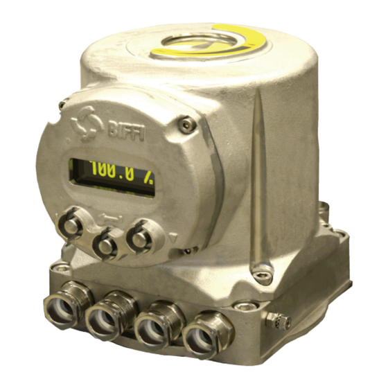
Page 13: Identification Of The Main Parts
MODBUS Card (MODBUS-RTU) Identification of the Main Parts In this section, only the main parts of the IMVS2000v2 are shown. Refer to the “PARTS LIST” paragraph, for a full list of the IMVS2000v2 parts. The IMVS2000v2 device is composed by three main parts:... - Page 14 Section 4: Device Description Installation, Operation and Maintenance Manual MAN720_IMVS2000v2_IOM Rev. 6 September 2019 Figure 1 The screws fixing the enclosure covers are made in Stainless Steel Class A4, grade 70, with a minimum yield strength 450 N/mm². The shaft, which transmits the movement from the valve to the internal position sensor, is supported by a bush mounted on the sensors’...
- Page 15 Installation, Operation and Maintenance Manual Section 4: Device Description MAN720_IMVS2000v2_IOM Rev. 6 September 2019 Figure 2 Pos. Description Position Sensor Assembly Barrier Card Display / Logic Cable Pressure Sensor Position Indicator Base Power Card Bus Card (OPT.) Display Card Logic Card Device Description...
-
Page 16: Technical Specifications
Section 4: Device Description Installation, Operation and Maintenance Manual MAN720_IMVS2000v2_IOM Rev. 6 September 2019 Technical Specifications Table 1. Device Power Supply (#) 19.2 Vdc - 57.6 Vdc (24 Vdc -20% - 48 Vdc +20%) Supply Voltage Range 19.2 Vdc – 35 Vdc for CSA/CSAus device 125 mA @ 24 Vdc (3 W) Maximum Device Current Consumption 62.5 mA @ 48 Vdc (3 W) - Page 17 Consult Factory for availability. (**) Consult Factory for applications over 345 barg. (***) Contact Biffi for the availability of applications that do not respect these ranges. (****) Ratio greater than 5 affects the accuracy of the PST. (particularly for pneumatic application) (*****) See [3] for details.
-
Page 18: Overall Dimensions
Section 4: Device Description Installation, Operation and Maintenance Manual MAN720_IMVS2000v2_IOM Rev. 6 September 2019 Overall Dimensions Figure 3 Options See Section 14 for the available options. Device Description... -
Page 19: Section 5: Working Principle And Detailed Description
The IMVS2000v2 can automatically find the mechanical stoppers through the “Calibration” command (see Section 5.1.1 for details). The IMVS2000v2 can perform both Partial Stroke (PST) and to the Full Stroke (FST) in opening and closing and also a SOV Test (in some particular configurations). -
Page 20: Calibration
The Baseline Signature is a mandatory operation for using the IMVS2000v2. It must be performed as second step of the Commissioning Procedure (see 10.7 for details). It allows the IMVS2000V2 to record the reference times and pressures of the Opening FST and of the Closing FST. -
Page 21: Opening And Closing Fst (External Source)
It is possible to store the FST data, only if a Baseline Signature is already successfully executed. To use the IMVS2000v2 at its own best, it is recommended to open and close the actuator when pressures and position are stable (see Section 5.2.8.1 for details). -
Page 22: Sovs Test
“normal” working position (e.g. Open position for a “fail to close” actuator) 5.1.5 SOVs Test The IMVS2000v2 can control up two external SOVs with independent and isolated circuits. The IMVS2000v2 can perform the SOV test to check the SOV integrity if: A single SOV is present Two SOVs are connected in series See 6.2 for details. - Page 23 (RL B CMD). The SOV TEST is executed only on to the SOV B. The SOV B is not involved in the other commands of the IMVS2000v2 (Calibration, Signatures and PST), for these commands the SOV A is used.
-
Page 24: Closing Fst Details
The position is expressed as % of the Open Position (100% = Open Position, 0% = Closed Position). The Closing Maximum Time is the total time of the Closing FST Graph. It is automatically calculated by the IMVS2000v2 (set equal to the Calculated Closing Time). See Section 5.2.8 for details. -
Page 25: Opening Fst Details
The Opening Maximum Time is the total time of the Opening FST Graph. It is automatically calculated by the IMVS2000v2 (set equal to the Calculated Opening Time). See 5.2.8 for details. For the Double Acting actuator, the Opening Break Pressure is expressed as the absolute value of the difference between the Pressure 1 (pressure sensor S1) and the Pressure 2 (pressure sensor S2). -
Page 26: Pst And Sov Test Details
Manual PST and if they do not respect the set tolerances, dedicated alarms can be activated (see Sections 5.2.7 and 8 for details). The Partial Closing Stroke can be performed only if the actuator is open and if the IMVS2000v2 is configured as fail to close (“Fail Mode” = “CL”). - Page 27 Manual PST and if they do not respect the set tolerances, dedicated alarms can be activated (see Sections Sections 5.2.7 and 8 for details). The Partial Closing Stroke can be performed only if the actuator is closed and if the IMVS2000v2 is configured as fail to open (“Fail Mode” = “OP”).
- Page 28 PST. After each performed PST, the IMVS2000v2 reverses the solenoid valve test sequence. It is possible to configure the IMVS2000v2 to test the SOVs individually (“PST Ser. SOVS” = “One”) During the first PST the SOVA is used to get the setpoint of the PST and the SOVB is not tested.
- Page 29 SOV B is just used for its own SOV TEST (picture above). The SOV TEST is executed only on to the SOV B. The SOV B is not involved in the other commands of the IMVS2000v2 (Calibration, Signatures and PST), for these commands the SOV A is used.
- Page 30 During the SOV TEST, the SOV A is briefly used for a short period of time to generate a pressure drop inside the cylinder (detected by pressure sensor) without generating the actuator’s movement. The “SOV TEST Time” is automatically set by the IMVS2000v2. The SOV A TEST is executed only on to the SOV A.
- Page 31 Installation, Operation and Maintenance Manual Section 5: Working Principle MAN720_IMVS2000v2_IOM Rev. 6 September 2019 If the “Baseline SOV A Test” command is received, but: “Cal. Status” ≠ “Passed” or “Base. S. St.” ≠ “Passed” or “Pr. S. 1-2” = “None” or “Al.
- Page 32 Section 5: Working Principle Installation, Operation and Maintenance Manual MAN720_IMVS2000v2_IOM Rev. 6 September 2019 If a problem is verified during the SOV A TEST execution: “PST St.” assumes the value “Failed” “M. PST Date” and “M. PST Time” assume the current date and time values The PSA Alarm is activated The DO PST PASSED contact is opened The DO PST FAILED contact is closed...
- Page 33 (detected by pressure sensor) without generating the actuator movement. The “SOV TEST Time” is automatically set by the IMVS2000v2. The first SOV tested is always the SOV A. If a problem is verified during the test on the SOV A, the test on the SOV B is executed anyway.
- Page 34 Section 5: Working Principle Installation, Operation and Maintenance Manual MAN720_IMVS2000v2_IOM Rev. 6 September 2019 The “SOV A – SOV B Test” can be performed by using “Manual PST” command or DI “PST CONTROL." “PST St.” describes the result of the last “SOV A – SOV B TEST." “M.
-
Page 35: Detailed Description
• MODBUS (see [3] for details) 5.2.1.1 Local Keypad and Display The IMVS2000v2 is fitted with a graphic 128x64 OLED display and 3 push-buttons that allows setting the configuration parameters or to visualize the working data. “UP” push-bu�on “SELECT” push-bu�on “DOWN”... - Page 36 Section 5: Working Principle Installation, Operation and Maintenance Manual MAN720_IMVS2000v2_IOM Rev. 6 September 2019 The SOLENOID A CONTROL and the SOLENOID B CONTROL are used for managing the external Solenoid Valves and their status determines the Position Request (see Sections 5.2.2.1 and 5.2.2.2 for details). The SOLENOID A CONTROL and SOLENOID B CONTROL can also be used for the SOVs TEST (see Section 5.2.2.1 for details).
- Page 37 Installation, Operation and Maintenance Manual Section 5: Working Principle MAN720_IMVS2000v2_IOM Rev. 6 September 2019 Type of Name Terminals # Type Description Command When activated a “Manual PST”/”SOV Test” command is performed. It’s usually used for launching a Manual PST Command. If “PST En.”...
-
Page 38: Digital Output
• Up to 57.6 Vdc – 0.5 A They are SPST solid state dry contacts. When the IMVS2000v2 is not power supplied the DOs are all open contacts. The OPEN, CLOSED and COMMON FAILURE ALARM digital outputs can be configured to work as normally open or normally closed contacts (see Section 5.2.3.1 for details). -
Page 39: Sis Signals - Sov Outputs
Both SIS A and SIS B power supply are continuously monitored and dedicated alarms can be generated (see Section 5.2.7 for details). If the SIS A signal is not applied the IMVS2000v2 cannot energize the SOVA; when the SIS A is removed the SOVA is “automatically” de-energized. -
Page 40: Pressure Sensors
Installation, Operation and Maintenance Manual MAN720_IMVS2000v2_IOM Rev. 6 September 2019 5.2.6 Pressure Sensors The IMVS2000v2 can be equipped with up to three internal pressure sensors (see Section 10.5 for details): • Pressure Sensor S1 – Pressure 1 • Pressure Sensor S2 – Pressure 2 •... -
Page 41: Graphs - Sampling Time - Memory
The time length of the PST is determined by the parameter PST Maximum Time that is automatically set equal to the PST Calculated Time (see Section 6 for details). The time length of the SOV Test is automatically calculated by the IMVS2000v2 during the Baseline Signature and it can’t be modified. - Page 42 The FST is memorized only if the position changes at least 1% in a time equal to the Opening Break Time (for the Opening FST) or the Closing Break Time (for the closing FST). If the position is greater than 50% the IMVS2000v2 can detect Closing FST generated by External Sources otherwise it can detect Opening FST.
-
Page 43: Section 6: Configuration Parameters
Local Operator Interface, see 7. For details about the mapping of the parameters on the “Biffi-Assistant” SW tool (RS232 and Bluetooth), see [1]. For details about the mapping of the parameters on the Bus Interfaces see the relevant manuals. - Page 44 (see Section 8). It is applicable only if “Act. Mode” is “Single” or “Double-S”. It deals with the number of SOVs managed by the IMVS2000v2. ”Simplex” = single SOV or 2 SOVs in series (it Simplex, SOVs Qty Local, Serial, depends on the value of “”PST Ser.
- Page 45 Installation, Operation and Maintenance Manual Section 6: Configuration Parameters MAN720_IMVS2000v2_IOM Rev. 6 September 2019 PARAMETERS OF THE “VIEW/SETUP MODE” MENU DEFAULT AVAILABLE PARAMETER NAME DESCRIPTION RANGE VALUE ON (2) (3) Sign. En. If it is set as “Yes” it is possible to perform com- Local, Serial, (Signatures Enabled) mands “Baseline Signature”...
- Page 46 Section 6: Configuration Parameters Installation, Operation and Maintenance Manual MAN720_IMVS2000v2_IOM Rev. 6 September 2019 PARAMETERS OF THE “VIEW/SETUP MODE” MENU DEFAULT AVAILABLE PARAMETER NAME DESCRIPTION RANGE VALUE ON (2) (3) It is applicable only if the Process Pressure Sensor is present (“Proc. S” is not set to “None”). It defines the threshold for the generation LPP 0 –...
- Page 47 Installation, Operation and Maintenance Manual Section 6: Configuration Parameters MAN720_IMVS2000v2_IOM Rev. 6 September 2019 PARAMETERS OF THE “VIEW/SETUP MODE” MENU DEFAULT AVAILABLE PARAMETER NAME DESCRIPTION RANGE VALUE ON (2) (3) It is applicable only if “Act. Mode” ≠ “Double” and “Pr.
- Page 48 Section 6: Configuration Parameters Installation, Operation and Maintenance Manual MAN720_IMVS2000v2_IOM Rev. 6 September 2019 PARAMETERS OF THE “VIEW/SETUP MODE” MENU DEFAULT AVAILABLE PARAMETER NAME DESCRIPTION RANGE VALUE ON (2) (3) It determines the “duration” of the graph of the opening FST. It is set by default at the same value of “Op.
- Page 49 Installation, Operation and Maintenance Manual Section 6: Configuration Parameters MAN720_IMVS2000v2_IOM Rev. 6 September 2019 PARAMETERS OF THE “VIEW/SETUP MODE” MENU DEFAULT AVAILABLE PARAMETER NAME DESCRIPTION RANGE VALUE ON (2) (3) It is the status of the last closing FST. It is “Not Done” if no Closing FST is performed yet.
- Page 50 Section 6: Configuration Parameters Installation, Operation and Maintenance Manual MAN720_IMVS2000v2_IOM Rev. 6 September 2019 PARAMETERS OF THE “VIEW/SETUP MODE” MENU DEFAULT AVAILABLE PARAMETER NAME DESCRIPTION RANGE VALUE ON (2) (3) The FST Type, FST Source, FST Status, FST date and time, FST Break and Travel Times, FST Break Pres- sure of the selected FST (“FST ID”) are shown.
- Page 51 Pressure 1 and 2. It is the pressure measured during last required (managed by the IMVS2000v2) Closing FST when the position reaches 100% - “Op. Break M. Cl. B. P.
- Page 52 Section 6: Configuration Parameters Installation, Operation and Maintenance Manual MAN720_IMVS2000v2_IOM Rev. 6 September 2019 PARAMETERS OF THE “VIEW/SETUP MODE” MENU DEFAULT AVAILABLE PARAMETER NAME DESCRIPTION RANGE VALUE ON (2) (3) It is the command for performing the “Manual PST”/”SOV Test.” “Manual PST”...
- Page 53 Installation, Operation and Maintenance Manual Section 6: Configuration Parameters MAN720_IMVS2000v2_IOM Rev. 6 September 2019 PARAMETERS OF THE “VIEW/SETUP MODE” MENU DEFAULT AVAILABLE PARAMETER NAME DESCRIPTION RANGE VALUE ON (2) (3) It is the status of the last “Manual PST” or ”SOVs Test.”...
- Page 54 Section 6: Configuration Parameters Installation, Operation and Maintenance Manual MAN720_IMVS2000v2_IOM Rev. 6 September 2019 PARAMETERS OF THE “VIEW/SETUP MODE” MENU DEFAULT AVAILABLE PARAMETER NAME DESCRIPTION RANGE VALUE ON (2) (3) The PST Type, PST Setpoint, PST Source, PST SOV, PST Status, PST date and time, PST Break and Travel Times, PST Break Pressure of the selected PST (“PST ID”) are shown.
- Page 55 Pressure 1 and 2. It is the date (dd-mm-yyyy) “updated” by the 01-01-2014 Local, Serial, Date actual RTC of the IMVS2000v2. 31-12-2099 It is the time (hh:mm:ss) “updated” by the RTC 00.00.00 Local, Serial, Time actual of the IMVS2000v2.
- Page 56 Section 6: Configuration Parameters Installation, Operation and Maintenance Manual MAN720_IMVS2000v2_IOM Rev. 6 September 2019 PARAMETERS OF THE “VIEW/SETUP MODE” MENU DEFAULT AVAILABLE PARAMETER NAME DESCRIPTION RANGE VALUE ON (2) (3) This command clears the Alarms List. Local, Serial, Clear Alarms List Start See Section 8 for details.
- Page 57 Installation, Operation and Maintenance Manual Section 6: Configuration Parameters MAN720_IMVS2000v2_IOM Rev. 6 September 2019 PARAMETERS OF THE “VIEW/SETUP MODE” MENU DEFAULT AVAILABLE PARAMETER NAME DESCRIPTION RANGE VALUE ON (2) (3) Set as “No” it is disabled. Set as “CFA” it is enabled and associated to the Al.
- Page 58 Section 6: Configuration Parameters Installation, Operation and Maintenance Manual MAN720_IMVS2000v2_IOM Rev. 6 September 2019 PARAMETERS OF THE “VIEW/SETUP MODE” MENU DEFAULT AVAILABLE PARAMETER NAME DESCRIPTION RANGE VALUE ON (2) (3) Set as “No” it is disabled. Set as “CFA” it is enabled and associated to the “CFA St.”...
- Page 59 CFA, ALR, No (Alarm MNT Enabled) Set as “ALR” it is enabled but not associated to the “CFA St.” See Sections 5.2.7, 8 and 5.2.3 for details. 19200, RS232 Baud For Biffi Use only (Factory Password). 115200 Local 115200 Table of Contents...
- Page 60 Section 6: Configuration Parameters Installation, Operation and Maintenance Manual MAN720_IMVS2000v2_IOM Rev. 6 September 2019 PARAMETERS OF THE “VIEW/SETUP MODE” MENU DEFAULT AVAILABLE PARAMETER NAME DESCRIPTION RANGE VALUE ON (2) (3) It defines the measure unit of the pressure. After changing its value the pressures of the “Normal Mode Menu”...
- Page 61 Installation, Operation and Maintenance Manual Section 6: Configuration Parameters MAN720_IMVS2000v2_IOM Rev. 6 September 2019 PARAMETERS OF THE “VIEW/SETUP MODE” MENU DEFAULT AVAILABLE PARAMETER NAME DESCRIPTION RANGE VALUE ON (2) (3) It indicates the presence of voltage on the PST CONTROL digital input. DI_PST St.
-
Page 62: Normal Mode Menu
(“Proc. S.” ≠ “None”). It is the time “updated” by the RTC of the 00-00-00 Local, Serial, actual Date IMVS2000v2. 23-59-59 It is the date “updated” by the RTC of the 01-01-3013 Local, Serial, Time actual IMVS2000v2. -
Page 63: Act.mode"And "Sovs Qty
Installation, Operation and Maintenance Manual Section 6: Configuration Parameters MAN720_IMVS2000v2_IOM Rev. 6 September 2019 “Act.Mode”and “SOVs Qty” Table 7. “Act. Mode” “Act. Mode” “SOVs Qty” Actuator Type “SOVs Qty” Actuator Type “PST Ser. SOVs” “PST Ser. SOVs” Double Acting with one SOV. Single Acting with one SOV. -
Page 64: Section 7: Local Operator Interface
This section describes the Local Operator Interfaces that is available by using the local Push-buttons and the display. The IMVS2000v2 is fitted with a graphic 128x64 OLED display and 3 push-buttons that allows entering the configuration parameters or to visualize the working data. -
Page 65: Normal Mode Menu
Installation, Operation and Maintenance Manual Section 7: Local Operator Interface MAN720_IMVS2000v2_IOM Rev. 6 September 2019 Normal Mode Menu The Normal Mode Menu is composed by four display-screens, which are available without any password and can give some general pieces of information. Figure 13 First Display -Screen after the Power -on... -
Page 66: Log In Menu
September 2019 Log in Menu The Login Menu allows entering the View/Setup Mode Menu logged in as “Observer, “User,” “VAC,” or “Factory.” The “VAC” and “Factory” passwords are reserved for Biffi Service and Production. Figure 14 DOWN Select User: Select User:... -
Page 67: View/Setup Mode Menu
To help reading the View Graph, a different color is associated to the different menu entries. Table 8. Menu and Sub-Menu Exit of Menu and Sub-Menu Available Parameter Available Command/Calibration Available Command/Parameter for VAC only (for Biffi use only) Unavailable Command/Parameter (for Biffi use only) View Mode Menu Setup Mode Menu Exit View-Setup Name Plate... - Page 68 Section 7: Local Operator Interface Installation, Operation and Maintenance Manual MAN720_IMVS2000v2_IOM Rev. 6 September 2019 HW Settings Exit HW Settings Act. Mode Open. Rot. Fail Action SOVs Qty Pr. S. 1-2 Proc. S. Set Pr. 1-2 Set Proc. RL A Cmd. RL B Cmd.
- Page 69 Installation, Operation and Maintenance Manual Section 7: Local Operator Interface MAN720_IMVS2000v2_IOM Rev. 6 September 2019 Signatures-FST Exit Signatures-FST Base. Sig. Cmd Mnt. Sig. Cmd Op. Cal. T. Op. Max. T. Cl. Cal. T. Cl. Max. T. Base. S. St. B.S. Date B.S.
- Page 70 Section 7: Local Operator Interface Installation, Operation and Maintenance Manual MAN720_IMVS2000v2_IOM Rev. 6 September 2019 Date and Time Exit Date and Time Date Time N.M. Date RTC Adjust Date and Time Exit Date and Time CFA St. Alarms Status Alarms List Clear Alarms List Reset Alarms Alarms Enabled...
- Page 71 Installation, Operation and Maintenance Manual Section 7: Local Operator Interface MAN720_IMVS2000v2_IOM Rev. 6 September 2019 Options Exit Options RS232 Baud Pres. M.U. CFA Mode Op. Cl. Mode Bus Type Blue. En. Change User PWD M.FST Al. En. Sensors Calibration Bus (*) Factory Settings Exit Factory Settings Pressure Calib.
-
Page 72: Push-Buttons Functionality
Section 7: Local Operator Interface Installation, Operation and Maintenance Manual MAN720_IMVS2000v2_IOM Rev. 6 September 2019 7.3.2 Push-buttons Functionality Two push-buttons “DOWN”, “UP” are used: to move into the Menus and the Sub-Menus to change the value of a selected parameter The Menus and Sub-Menus are not “circular”. -
Page 73: Section 8: Table Of Alarms
Section 8: Table of Alarms Installation, Operation and Maintenance Manual MAN720_IMVS2000v2_IOM Rev. 6 September 2019 Section 8: Table of Alarms Table 9. Alarm Acronym Composition Squelched By (*) (**) (***) The “PST Cycle Count” exceeds the “PST Cycle Limit” • “Al. - Page 74 Section 8: Table of Alarms Installation, Operation and Maintenance Manual MAN720_IMVS2000v2_IOM Rev. 6 September 2019 Alarm Acronym Composition Squelched By (*) (**) (***) • “Al. PSLB En.” = “No” Last “Manual PST Break Pressure” is lower than the “Baseline • “M.
- Page 75 Section 8: Table of Alarms Installation, Operation and Maintenance Manual MAN720_IMVS2000v2_IOM Rev. 6 September 2019 Alarm Acronym Composition Squelched By (*) (**) (***) In case of “Position Request” = 0%: the actual position differs from the Position Request (0%) by more than the “Closed Position Hysteresis”...
- Page 76 Section 8: Table of Alarms Installation, Operation and Maintenance Manual MAN720_IMVS2000v2_IOM Rev. 6 September 2019 Alarm Acronym Composition Squelched By (*) (**) (***) The “FST Cycle Count” exceeds the “FST Cycle Limit” “FST Cyc. Cnt” >= “FST Cyc. Lim.” • “Al.
- Page 77 “Reset Alarms” command. Notes: (*): See Section 6 for details about IMVS2000v2 parameters. (**): The Cyclically Check alarms are not permanently squelched by the “Reset Alarms” command and by the “Power on Reset”, if the alarm conditions keep existing, they will be activated during the next check (see Section 5.2.7).
-
Page 78: Section 9: Wiring Diagrams - Signals Description
Display Card Terminals 1-24 (Base Power Card) The previous figure shows the standard terminals (without optional cards) of the IMVS2000v2. The table below describes the signals of the standard terminals of the IMVS2000v2. Wiring Diagrams - Signals Descriptions... - Page 79 Installation, Operation and Maintenance Manual Section 9: Wiring Diagrams - SIgnals Description MAN720_IMVS2000v2_IOM Rev. 6 September 2019 Table 10. Type Signal Name Description EARTH Protection Earth. EARTH EARTH Protection Earth. EARTH Protection Earth. +Vin Positive Input of the power supply of the electronic cards. Main Supply -Vin Negative Input of the power supply of the electronic cards.
-
Page 80: Optional Card Signals
Hart Card Signals Figure 16 Terminals 38-41 (HART Card) The previous figure shows the terminals of the IMVS2000v2 HART Card. The table below describes the signals of the of the HART Card terminals (for details see [2]). Table 11. Type... - Page 81 September 2019 9.1.2.2 Modbus Card Signals Figure 17 The previous figure shows the terminals of the IMVS2000v2 MODBUS Card. The table below describes the signals of the of the MODBUS Card terminals (for details see [3]). Table 12. Type Signal Name...
-
Page 82: Wiring Diagrams
Section 9: Wiring Diagrams - SIgnals Description Installation, Operation and Maintenance Manual MAN720_IMVS2000v2_IOM Rev. 6 September 2019 Wiring Diagrams 9.2.1 Configuration A – Wiring Diagram Figure 18 Mandatory Connections: MAIN SUPPLY (terminals 3-4) SIS A SUPPLY (terminals 5-6) SOVA (terminals 9-11) All the other connections are optional (see Section 9.1.1 for details). -
Page 83: Configuration B - Wiring Diagram
Installation, Operation and Maintenance Manual Section 9: Wiring Diagrams - SIgnals Description MAN720_IMVS2000v2_IOM Rev. 6 September 2019 9.2.2 Configuration B – Wiring Diagram Figure 19 Mandatory Connections: MAIN SUPPLY (terminals 5-6) SOVA (terminals 9-11) Recommended Connections: SOLENOID A CONTROL (terminals 19-20) All the other connections are optional (see Section Section 9.1.1 for details). -
Page 84: Configuration C - Wiring Diagram
Section 9: Wiring Diagrams - SIgnals Description Installation, Operation and Maintenance Manual MAN720_IMVS2000v2_IOM Rev. 6 September 2019 9.2.3 Configuration C – Wiring Diagram Figure 20 Mandatory Connections: MAIN SUPPLY (terminals 3-4) SIS A SUPPLY (terminals 5-6) SIS B SUPPLY (terminals 12-13) SOVA (terminals 9-11) SOVB (terminals 16-18) All the other connections are optional (see Section 9.1.1 for details). -
Page 85: Configuration D - Wiring Diagram
Installation, Operation and Maintenance Manual Section 9: Wiring Diagrams - SIgnals Description MAN720_IMVS2000v2_IOM Rev. 6 September 2019 9.2.4 Configuration D – Wiring Diagram Figure 21 Mandatory Connections: MAIN SUPPLY (terminals 5-6) SOVA (terminals 9-11) SOVB (terminals 16-18) Recommended Connections: SOLENOID A CONTROL (terminals 19-20) SOLENOID B CONTROL (terminals 21-22) All the other connections are optional (see Section 9.1.1 for details). -
Page 86: Configuration E - Wiring Diagram
Section 9: Wiring Diagrams - SIgnals Description Installation, Operation and Maintenance Manual MAN720_IMVS2000v2_IOM Rev. 6 September 2019 9.2.5 Configuration E – Wiring Diagram Figure 22 Mandatory Connections: MAIN SUPPLY (terminals 3-4) SIS A SUPPLY (terminals 5-6) SOVA (terminals 9-11) SOVB (terminals 16-18) Recommended Connections: SOLENOID A CONTROL (terminals 19-20) SOLENOID B CONTROL (terminals 21-22) -
Page 87: Configuration F - Wiring Diagram
Installation, Operation and Maintenance Manual Section 9: Wiring Diagrams - SIgnals Description MAN720_IMVS2000v2_IOM Rev. 6 September 2019 9.2.6 Configuration F – Wiring Diagram Figure 23 Mandatory Connections: MAIN SUPPLY (terminals 5-6) SOVA (terminals 9-11) SOVB (terminals 16-18) Recommended Connections: SOLENOID A CONTROL (terminals 19-20) SOLENOID B CONTROL (terminals 21-22) All the other connections are optional (see Section 9.1.1 for details). -
Page 88: Configuration G - Wiring Diagram
Section 9: Wiring Diagrams - SIgnals Description Installation, Operation and Maintenance Manual MAN720_IMVS2000v2_IOM Rev. 6 September 2019 9.2.7 Configuration G – Wiring Diagram Figure 24 Mandatory Connections: MAIN SUPPLY (terminals 5-6) SOVA (terminals 9-11) All the other connections are optional (see Section 9.1.1 for details). Wiring Diagrams - Signals Descriptions... -
Page 89: Configuration H - Wiring Diagram
Installation, Operation and Maintenance Manual Section 9: Wiring Diagrams - SIgnals Description MAN720_IMVS2000v2_IOM Rev. 6 September 2019 9.2.8 Configuration H – Wiring Diagram Figure 25 Mandatory Connections: MAIN SUPPLY (terminals 3-4) SIS A SUPPLY (terminals 5-6) SOVA (terminals 9-11) SOVB (terminals 16-18) Wiring Diagrams - Signals Descriptions... -
Page 90: Hart Card - Wiring Diagram
Section 9: Wiring Diagrams - SIgnals Description Installation, Operation and Maintenance Manual MAN720_IMVS2000v2_IOM Rev. 6 September 2019 All the other connections are optional (see Section 9.1.1 for details). 9.2.9 Hart Card – Wiring Diagram Figure 26 The HART Card is optional. 9.2.9.1 Modbus Card –... -
Page 91: Section 10: Installation - Start-Up
Section 10: INSTALLATION – START-UP If ordered as part of an actuator, the factory mounts the IMVS2000v2 device on the actuator, makes pneumatic connections to the actuator, sets up and calibrates the instrument. If IMVS2000v2 device is purchased separately, you will need a mounting kit to mount the device on the actuator. -
Page 92: Installation In Ambient With Explosive Dusts
(see the certificates delivered with the IMVS2000v2, if available, or the IMVS2000v2 nameplate); 2. Gather the necessary tools for the assembly and setting of the IMVS2000v2 controls; 3. Check that the coupling dimensions of the actuator flange and stem meet the IMVS2000v2 coupling dimensions;... -
Page 93: Preliminary Operations
(please refer to the picture below). Figure 28 POSITION SHAFT The IMVS2000v2 position is shown by the orientation of the indicator arrow in the upper window (in the pictures below are shown the CLOSED and OPEN position). Figure 29... -
Page 94: Mechanical Connections
IMVS2000v2 position shaft is mounted correctly onto the male part of actuator joint (2); • Tighten the 4 screws (6) and nuts (7) in order to fix the IMVS2000v2 device onto the bracket; and • The picture below shows the IMVS2000v2 device assembled onto the actuator. -
Page 95: Mounting Imvs2000V2 Onto Alga/Algas Type Actuators
(4) is opposite to the actuator control panel (5); and • Tighten the 4 screws (3) in order to fix the IMVS IMVS2000v2 device and the spacer on to the actuator. The picture below shows the IMVS2000v2 device assembled onto the actuator. -
Page 96: Pressure Connections
The sealing of cables and/or conduit entries must be carried out in accordance with National Standards or the Regulatory Authorities that have certified the IMVS2000v2. Method of sealing and cable glands must be approved and separately certified for use in hazardous areas. - Page 97 The cables MUST be selected considering the maximum Temperature of the cable indicated on the label fixed to the IMVS2000v2 Enclosure. Connect the external wires in accordance with the wiring diagram attached to the documentation of IMVS2000v2. For details about the signals connection see 9. Installation – Start-Up...
-
Page 98: Removing The Electrical Enclosure's Covers
The user shall be aware that all external fasteners on which the flameproof enclosure depends are stainless steel socket head cap screws class A4 -grade 70. WARNING During the opening and closing the IMVS2000v2 units, pay attention not to damage the joint surface of the covers and of the base manifold. WARNING Follow the procedure below for removing the covers. - Page 99 Installation, Operation and Maintenance Manual Section 10: Installation – Start-Up MAN720_IMVS2000v2_IOM Rev. 6 September 2019 Figure 36 Using a 4 mm Allen key, loosen the four screws fixing the local interface cover and remove it. At the end of wiring connections replace the cover and fix the 4 screws with a tightening torque from 4 to 5 Nm.
-
Page 100: Unused Entries
10.6.4 Cables requirements – EMC protection The table below summarizes the specifications of the cables, for connecting with the IMVS2000v2. Particularly, it indicates if a cable needs to be armoured or shielded. “Shielded” must be considered as a stricter condition than “Armoured."... -
Page 101: Wires Dimensions
The first thing to be done during the commissioning is to correctly configure the IMVS2000v2. For performing the commission procedure, the IMVS2000v2 must be able to open and close the valve/actuator. -
Page 102: Section 11: Parts List
Section 11: Parts List Installation, Operation and Maintenance Manual MAN720_IMVS2000v2_IOM Rev. 6 September 2019 Section 11: Parts List This section includes the drawings and the parts’ list of the General Assembly and of the Spare Parts of the ELBS-20. Impornant: This section includes the drawings and the parts’... - Page 103 PLUG M20 EP435 /M20x1.5 - OTM POSITION LABEL POSITION SENSOR ASSEMBLY RELIEF BLOCK BASE POWER CARD BUS CARD (OPTIONAL) 1 (***) COVER ASM FOR LOCAL DISPLAY BASE COVER WITH WINDOW ASM DISPLAY CARD IMVS2000v2 PRESSURE SENSOR 0-3 (**) Parts List...
-
Page 104: Spare Parts
Qty. POSITION SENSOR ASSEMBLY 4400000011 BARRIER CARD 492BAR1000 LOGIC-DISPLAY CABLE 492IMVSCB1 434IMV1000 (10 bar) 434IMV2000 (100 bar) IMVS2000v2 PRESSURE SENSOR 434IMV3000 (200 bar) 434IMV5000 (400 bar) POSITION INDICATOR 3340030110 BASE POWER CARD 492IM30100 492IM30400 (HART) BUS CARD (OPTIONAL) 492IM30500 (MODBUS) -
Page 105: Section 12: Decommissioning
Decommissioning Figure 42 Disposal and recycling At the end of the life of IMVS2000v2, the device must be disassembled. WARNING Do not dump non-biodegradable products, lubricants and non-ferrous (rubber, PVC, resins, etc.) into the environment. Dispose of all such materials as indicated in the following table: Table 16. -
Page 106: Section 13: Trouble Shooting
Moreover, the area must be cleaned from explosive mixture since batteries and power supply could generate electrical spark and cause explosion. WARNING During the opening and closing the IMVS2000v2 units, pay attention do not damage the joint surface of the covers. Table 17. - Page 107 Installation, Operation and Maintenance Manual Section 13: Trouble Shooting MAN720_IMVS2000v2_IOM Rev. 6 September 2019 Table 18. Detected problem Actions to be performed • verify the Main Supply on terminals 3 & 4. • verify that the wiring is correct. • verify the supply on terminals 5-6 and 12-13.
-
Page 108: Section 14: Ordering Table
4 = CSA: see paragraph 2.5.1 5 = CSAus: see paragraph 2.5.1 8) Shaft (1 Digit) B = Shaft Standard Biffi N = Shaft Namur Type Note: mounting KIT, when required, must be ordered separately by specifying the type of actuator (rotary or linear) and dimension of the interface. -
Page 109: Section 15: Document Revision
Installation, Operation and Maintenance Manual Section 15: Document Revision MAN720_IMVS2000v2_IOM Rev. 6 September 2019 Section 15: Document Revision Table 19. Rev. Date Description Prepared Approved 03/10/2014 First Issue Battaglia Comelli 08/11/2016 Second Issue Battaglia Comelli 11/11/2016 Third Issue Battaglia Comelli 04/10/2018 Fourth Issue Battaglia... - Page 110 ©2019 Biffi. All rights reserved. Biffi Italia s.r.l. Strada Biffi 165 The contents of this publication are presented for information purposes only, 29017 Fiorenzuola d’Arda (PC) and while every effort has been made to ensure their accuracy, they are not...
Need help?
Do you have a question about the IMVS2000v2 and is the answer not in the manual?
Questions and answers