
Subscribe to Our Youtube Channel
Related Manuals for Husqvarna K 3000-Electric


Summary of Contents for Husqvarna K 3000-Electric
- Page 1 Workshop manual K 3000- Electric, Wet, Cut-n-Break HUSQVARNA CONSTRUCTION PRODUCTS...
-
Page 2: Table Of Contents
CONTENTS Page HUSQVARNA LITERATURE 2. COMPONENTS – NAVIGATION K 3000 BASIC STRUCTURE 4. CARBON BRUSHES 5. CARBON BRUSH HOLDER 6. WIRING DIAGRAM, CABLING – 230 V 7. WIRING DIAGRAM, CABLING – 120 V 8. TESTING – ELECTRICAL COMPONENTS 9. ELECTRICAL CABLES, CONTACTS 10. - Page 3 The list of contents also has page references to the start of each chapter. Spares Spares K3000 The folders include all spares for Husqvarna IPL, K3000, K3000 Wet, 2008-05, 510 03 27-02 K3000. The K3000 Electric and Wet have a common...
-
Page 4: Components - Navigation
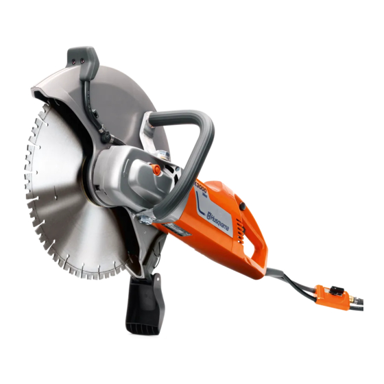
COMPONENTS – NAVIGATION K3000 Electric, Wet 1. Cutting blade 2. Blade guard 3. Spray nozzle, on each side (not Electric) 4. Front handle 5. Inspection cover for carbon brushes 6. Starter lock 7. Rear handle 8. Circuit breaker 9. Rotation lock 10. -
Page 5: Basic Structure
BASIC STRUCTURE K3000 Husqvarna's electrically driven power cutters are based on a common motor unit that allows wet cutting with a limited amount of water. The machine versions are shown in the illustration below. The workshop manual deals with the motor unit in a common section and the distinct parts for each machine in a chapter for each type of machine. -
Page 6: Carbon Brushes
CARBON BRUSHES Replacing the carbon brushes The two carbon brushes transfer electric current to the motor's rotor. The carbon brushes are wear parts that must be checked regularly; every week if the machine is used daily. You should replace the carbon brushes when around half is left. You can easily measure this using a slide gauge without removing the brushes. -
Page 7: Carbon Brush Holder
CARBON BRUSH HOLDER Replacing the carbon brush holder In order to replace the carbon brush holders, both the rear handle halves must be removed from the motor housing. Remove right handle Remove right handle Remove the inspection cover to Remove the inspection cover to the car- the carbon brushes. -
Page 8: Wiring Diagram, Cabling - 230 V
WIRING DIAGRAM, CABLING – 230 V Assembly diagram GREY Stator The assembly diagram shows the colours and positions of the connection cables GREY for the electrical connections. BLACK Rotor GREY BLACK Stator GREY GREEN/YELLOW WHITE BLACK BROWN BLACK Earth fault breaker BLUE WHITE GREEN/YELLOW... -
Page 9: Wiring Diagram, Cabling - 120 V
WIRING DIAGRAM, CABLING – 120 V Assembly diagram GREY Stator The assembly diagram shows the colours GREY and positions of the connection cables Rotor for the electrical connections. BLACK BLACK BLACK Stator BLACK WHITE WHITE Earth fault breaker BLACK GREEN/YELLOW Components/cables Illustration 1. -
Page 10: Testing - Electrical Components
TESTING – ELECTRICAL COMPONENTS Work procedure The electrical function is checked in the following chapter exclusively with a multimeter. No checks are made with the machine connected to the mains! The only exception is the function check of the earth fault breaker that is done without the machine or earth fault breaker being dis- mantled. -
Page 11: Electrical Cables, Contacts
ELECTRICAL CABLES – CONTACTS Test of mains cable The earth fault breaker does not allow the current to pass this when it is not connected to the mains supply. In order to check the mains cable with a multimeter, the earth fault breaker ends must be pulled apart to access the connection points. -
Page 12: Rotor
ROTOR Functional test Preparations Remove the inspection cover to the carbon brushes. Connect a measuring cable to each carbon brush. (You do not need to be concerned that the stator is connected at the carbon brushes as the stator's circuit board is broken at the circuit board and is therefore not affected by the measurement.) Measuring cables Use short measuring cables and lay these close to each other: the easiest way is... -
Page 13: Rotor - Replacement
ROTOR – REPLACEMENT Preparations K3000 Electric, Wet Removing the blade guard, see page 24. K3000 Cut-n-Break Removing the cutting unit and handle unit, see page 30. Remove right handle Remove right handle Remove the inspection cover to Remove the inspection cover to the car- the carbon brushes. -
Page 14: Stator - 230 V
STATOR – 230 V Functional test Fractures to the stator winding are easiest to indicate using the check below. In general, short-circuited windings can also be identified, particularly if the short circuit eliminates current in several winding turns. If the short circuit only eliminates a few turns, the measurement is unlikely to record this. -
Page 15: Stator - 120 V
STATOR – 120 V Functional test Fractures to the stator winding are easiest to indicate using the check below. In general, short-circuited windings can also be identified, particularly if the short circuit eliminates current in several winding turns. If the short circuit only eliminates a few turns, the measurement is unlikely to record this. -
Page 16: Stator - Replacement
STATOR – REPLACEMENT Remove right handle Remove right handle Remove the inspection cover to Remove the inspection cover to the car- the carbon brushes. bon brushes as per previous chapter. Remove the screws as shown in Remove the screws as per the illustration the illustration. -
Page 17: Gear Housing - Electric, Wet
GEAR HOUSING – Electric, Wet Alternative for dismantling The gear housing is accessible for dividing when the blade guard has been removed. Inspection of the crown gear and drive pinion, replacement of the blade shaft crown gear bearing and re-greasing the bearing housing can be done without removing any other parts. - Page 18 GEAR HOUSING – Electric, Wet Remove the gear housing Remove the gear housing Attach the rotor in a vice with Attach the rotor in a vice with rubber rubber jaws. jaws. Press a heavy metal object Press a heavy metal object against one against one corner of the gear corner of the gear housing.
- Page 19 GEAR HOUSING – Electric, Wet Fit gear housing bearings Fit gear housing bearings Fit the tool as per the illustra- Fit the tool as per the illustrations. tions. Place a large washer with Place a large washer above the nut (not the nut.
- Page 20 GEAR HOUSING – Electric, Wet Bearing replacement in Bearing replacement in cover cover Remove the annular gear for the blade Remove the bearing using a guard. Remove the bearing using a coun- counter stay device. ter stay device. Heating around the bea- ring seat helps if the bearing is firmly in Fit the bearing using the tool kit place.
-
Page 21: Gear Housing - Cut-N-Break
GEAR HOUSING – Cut-n-Break Alternative for dismantling The gear housing is accessible for division once the cutting unit has been removed, see page 30. Inspection of the crown gear unit and drive pinion, as well as re-greasing of the bearing housing is possible without removing any more parts. - Page 22 GEAR HOUSING – Cut-n-Break Remove the gear housing Remove the gear housing Attach the rotor in a vice with Attach the rotor in a vice with rubber rubber jaws. jaws. Press a heavy metal object Press a heavy metal object against one against one corner of the gear corner of the gear housing.
- Page 23 GEAR HOUSING – Cut-n-Break Fit gear housing bearings Fit gear housing bearings Fit the tool as per the illustra- Fit the tool as per the illustrations. tions. Place a large washer with the nut which Place a large washer with the serves as a dolly device in the gear nut.
-
Page 24: Cutting Unit - Electric, Wet
CUTTING UNIT – Electric, Wet Remove the blade guard The blade guard must be removed to access the gear housing's screws and divide the gear housing. You must divide the gear housing to be able to separate the motor from the gear housing, e.g. - Page 25 CUTTING UNIT – Electric, Wet Fit the blade guard – Fit the blade guard – tighten the screws alter- tighten the screws alternately nately The soft rubber ring under the washer is pressed together when the plate washer is fitted. The three screws must then be 1-4- 2-5- tightened alternately to avoid deforming...
-
Page 26: Cutting Unit - Cut-N-Break
CUTTING UNIT – Cut-n-Break Belt tensioning Belt tensioning Loosen one turn Loosen one turn Loosen both nuts that hold the cutting arm and the screw that locks the adjust- ment washer. Tighten the belt Tighten the belt ≈ 5 mm Turn the adjustment washer to Turn the adjustment washer using a ≈... - Page 27 CUTTING UNIT – Cut-n-Break Belt replacement Belt replacement Fold aside the splash guard Fold aside the splash guard Force off the rubber guard from Force off the rubber guard from the screw. the screw. Push the splash guard into smooth cut - Fold down the splash guard.
- Page 28 CUTTING UNIT – Cut-n-Break Bearing replacement Bearing replacement Remove the belt guards. The cutting arm, where the bearing is fitted, is now accessible when the belt guards are removed. See the “Belt replace- ment” chapter where this work is described. Attach the cutting arm.
- Page 29 CUTTING UNIT – Cut-n-Break Removal Removal Add a wooden block under the Add a wooden block under the cutting cutting arm. Place the ball bea- arm right next to the bearing holder. ring on the bearing holder and Place the ball bearing on the bearing knock so that a gap appears bet- holder and knock the outer ring so that a ween the bearing holder and...
- Page 30 CUTTING UNIT – Cut-n-Break Removal of complete cutting unit The cutting unit can be easily dismantled and refitted as a unit. This is appro- priate if work is to be carried out in the gear housing or if the motor unit is to be divided from the gear housing, for example, when replacing the rotor or stator.
-
Page 31: Wet System
WET SYSTEM Water coupling with flow control The water coupling with flow control is identical for all K3000 with wet systems. The water coupling is adapted to suit the Gardena® system. The coupling in the machines for wet cutting have a flow control that regulates to a virtually constant flow at varying water pressures. - Page 32 WET SYSTEM K3000 Wet Construction A spray nozzle is located on each side of the blade guard. The water strikes a section of the cutting blade and the centrifugal force carries it out towards the blade's diamond segments. The spray nozzles have a smaller diameter for the water spray compared to the petrol-driven cutters in order to restrict the amount of water.
-
Page 33: Tools
TOOLS = Service action ● The tools below can be acquired from Husqvarna: The special tools below are needed for servicing work on the K3000 but are not sold by Husqvarna: 506 37 61-02 Multimeter Bearing press Make: Amprobe 37XR-A. - Page 34 www.husqvarnacp.com 115 24 59-26 English 2009-06...
Need help?
Do you have a question about the K 3000-Electric and is the answer not in the manual?
Questions and answers