Sign In
Upload
Download
Table of Contents
Contents
Add to my manuals
Delete from my manuals
Share
URL of this page:
HTML Link:
Bookmark this page
Add
Manual will be automatically added to "My Manuals"
Print this page
×
Bookmark added
×
Added to my manuals
Manuals
Brands
Tritech Manuals
Sonar
SeaKing
Product manual
Tritech SeaKing Product Manual
Imaging sonar
Hide thumbs
1
2
Table Of Contents
3
4
5
6
7
8
9
10
11
12
13
14
15
16
17
18
19
20
21
22
23
24
25
26
27
28
29
30
31
32
33
34
35
36
37
38
39
40
41
42
43
44
45
46
47
48
49
50
51
52
53
54
page
of
54
Go
/
54
Contents
Table of Contents
Troubleshooting
Bookmarks
Table of Contents
Table of Contents
Warning Symbols
1 Introduction
2 Getting Started
3 Installation
General Overview
Seanet Pro Software
Installing the Sonar Head
Seaking Communication Configuration
Subsea Sensor Electrical Installation
Ground Fault Monitoring Equipment
Waterblock Pin-Out Diagram
4 Setup
Identifying the Model
Changing Configuration for Serial or ARCNET
Changing Configuration for Ethernet
5 Operation
Basic Principles
Operating the Seaking & Seaprince in Seanet Pro
Main Screen
Sonar Settings
Main Menu
Measurement Tool
Dynamic Range and Sonar Rx Indicator
Application Tools
6 Maintenance
After Using the Sonar
If Storing the Sonar for Extended Periods
Seaking Regular Maintenance
Disassembly of the Seaking Unit
Reassembly of the Seaking Unit
Super Seaprince Regular Maintenance
Disassembly of the Super Seaprince Unit
Reassembly of the Super Seaprince Unit
7 Troubleshooting
Help & Support
Specification
Seaking
Seaking Dimensions
Seaking Physical Properties
Seaking Acoustic Properties
Seaking Display Characteristics
Seaking Electrical and Communication
Seaprince
Seaprince Dimensions
Seaprince Physical Properties
Seaprince Acoustic Properties
Seaprince Display Characteristics
Seaprince Electrical and Communication
ARCNET Termination
CHIRP Signal Processing
Seaking Sonar & Profiler Connector Options
Super Seaprince External Reset
V6 COM PCB Reset
Glossary
Advertisement
Quick Links
1
Seaking Communication Configuration
2
Changing Configuration for Serial or Arcnet
Download this manual
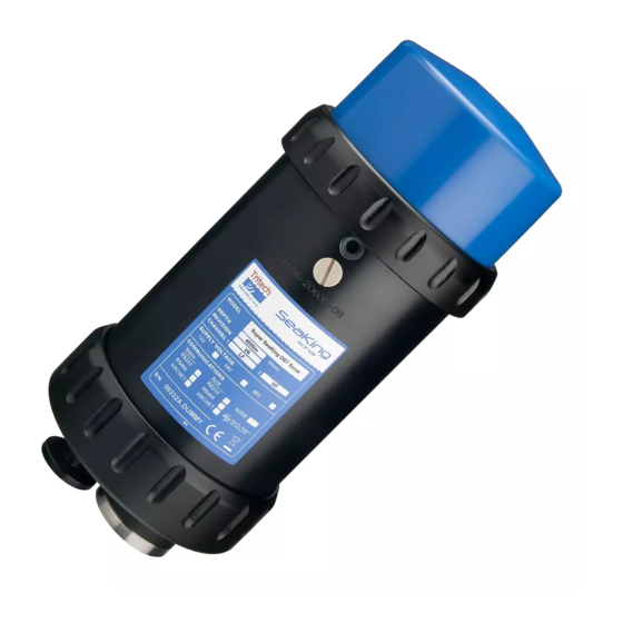
SeaKing & SeaPrince Imaging Sonars
SeaKing & SeaPrince
Imaging Sonars
Product Manual
0374-SOM-00001, Issue: 08
1
© Tritech International Ltd.
Table of
Contents
Previous
Page
Next
Page
1
2
3
4
5
Advertisement
Table of Contents
Need help?
Do you have a question about the SeaKing and is the answer not in the manual?
Ask a question
Questions and answers
Related Manuals for Tritech SeaKing
Sonar Tritech SeaKing Sidecan Operator's Manual
Seaking sidecan (84 pages)
Sonar Tritech StarFish Quick Start Manual
Towed sonar (2 pages)
Sonar Tritech SeaPrince Product Manual
Imaging sonar (54 pages)
Sonar Tritech Eclipse Product Manual
3d imaging sonar (44 pages)
Sonar Tritech Gemini 720ik Product Manual
(82 pages)
Sonar Tritech Gemini 1200id Product Manual
(37 pages)
Sonar Tritech Gemini 1200ik Product Manual
(19 pages)
Sonar Tritech Gemini Profiler Manual
(17 pages)
Sonar Tritech Gemini 720ik Product Manual
Diver mounted display (31 pages)
This manual is also suitable for:
Seaprince
Table of Contents
Save PDF
Print
Rename the bookmark
Delete bookmark?
Delete from my manuals?
Login
Sign In
OR
Sign in with Facebook
Sign in with Google
Upload manual
Upload from disk
Upload from URL


Need help?
Do you have a question about the SeaKing and is the answer not in the manual?
Questions and answers