Table of Contents
Advertisement
Quick Links
Advertisement
Table of Contents

Related Manuals for Tritech Gemini 720ik


Summary of Contents for Tritech Gemini 720ik
- Page 1 Diver Mounted Display (Un-Tethered) Product Manual 0747-SOM-00004...
-
Page 2: Table Of Contents
Table of Contents Warning Symbols ........................3 Help & Support .......................... 4 System Overview ........................5 Technical Specification ......................6 Physical Dimensions 1200ik & 720ik ..................6 Monocle Specifications ......................7 Subsea Computer (SSC) Specifications .................. 8 Battery Specifications ....................... 9 Hardware Installation &... -
Page 3: Warning Symbols
Warning Symbols 0747-SOM-00004-01 Page 3 of 31... -
Page 4: Help & Support
The name of the organisation which purchased the system is held on record at Tritech International Ltd and details of new software or hardware packages will be announced at regular intervals. This... -
Page 5: System Overview
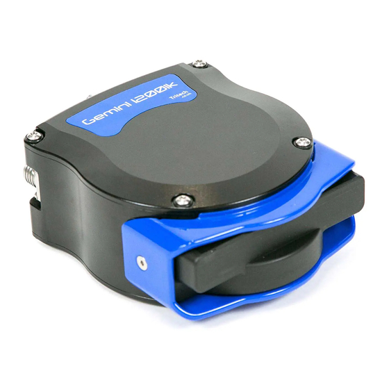
Employing a high degree of resolution and field of view the diver can opt for either the Gemini 720ik or Gemini 1200ik Multibeam imaging sonars, both provide excellent range, resolution and field of view. These high specification Multibeam imaging sonars provide a diver with a high degree of confidence while working in zero visibility conditions and allow searches to be undertaken far more efficiently than using conventional search pattern techniques. -
Page 6: Technical Specification
The system is designed to be used with our Gemini range of multibeam sonars, primarily the Gemini 1200ik and 720ik multibeam sonars fitted with an Inodive mounting plate. Physical Dimensions 1200ik & 720ik Please refer to the Gemini 1200ik & 720ik manuals available on our website www.tritech.co.uk full sonar specifications 0747-SOM-00004-01 Page 6 of 31... -
Page 7: Monocle Specifications
Monocle Specifications Monocle specification Power requirement 0.5W @ +5V DC Depth rating 100m Display input RGB, HSYNC, VSYNC Display resolution SVGA (800 X 600) Connector SubConn Micro Circular series Weight in water 0.09kg 0747-SOM-00004-01 Page 7 of 31... -
Page 8: Subsea Computer (Ssc) Specifications
Subsea Computer (SSC) Specifications Subsea computer Power requirement * 10W @ 20 - 42 VDC Depth rating 100m Connectors SubConn Micro Circular series Weight in water 0.54kg * Does not allow for attached accessories 0747-SOM-00004-01 Page 8 of 31... -
Page 9: Battery Specifications
Battery Specifications The Metalsub FX1210 with a fixed mounting plate Equipped with Metalsub's unique anodising layer, according to US Military Standards (MIL- A-8625-E type3 class2). This protective layer is also impregnated with Teflon, which guarantees a high degree of corrosion resistance. ... -
Page 10: Hardware Installation & Configuration
Hardware Installation & Configuration The full DMD-U system is contained within 2 separate rugged deployment transit cases : DMD-U Instrument Deployment Case DMD Sonar Deployment Case DMD-U Instrument Deployment Case The DMD Instrument Deployment case is a rugged transit case featuring bespoke cut-outs for safely storing and transporting all the items and accessories (other than the sonar head) required to install and deploy the system on site. - Page 11 S12412 1.5M DMD Sonar Cable S12507 SubConn MCDC10F S10071 SubConn MCDC8F S11541 SubConn MCDC6F S12508 SubConn MCDC12M Connector Dummy AC Mains Leads for Metalsub Charger Tritech Branded Cable Tie CASE LID Document Folder (Build Record) 0747-SOM-00004-01 Page 11 of 31...
-
Page 12: Dmd Sonar Deployment Case
DMD Sonar Deployment Case The DMD Sonar Deployment case is a rugged transit case featuring bespoke cut- outs for safely storing and transporting the Gemini 720ik or 1200ik multibeam sonar heads. SONAR CASE Gemini 1200ik or 720ik Sonar Spare storage... -
Page 13: System Connections
System Connections The diagram above shows the different parts and cable connections required to the SSC before the system is powered on and deployed. If not fitting the DMD Hand Controller (untethered operation) or Diver Comms connection (tethered operation) the Blanking Plug (item 4) must be fitted. Submerging the unit and powering ON with this connection exposed will result in damage to the SSC not covered under the warranty. -
Page 14: Assembly & Fitting Of Sonar Onto Mask (Using The Ots Accessory Rails)
Assembly & Fitting of Sonar onto Mask (Using the OTS Accessory Rails) The diagram above shows the parts required to construct and mount the sonar onto the OTS Guardian diver mask Item Part No. Description S12055 OTS Guardian Accessory Rail S12051 Spigot Assembly, 90 degree S12049... - Page 15 The illustrations below show the mounting fully assembled and attached to the side of the mask. During use the diver may find it helpful to reach up and adjust the orientation of the sonar slightly using gentle pressure to rotate it forward or backward on the mounting spigot.
-
Page 16: Assembly & Fitting Of Monocle Onto Mask (Using The Ots Accessory Rails)
Assembly & Fitting of Monocle onto Mask (Using the OTS Accessory Rails) The diagram above shows the parts required to assemble and mount the Monocle onto the OTS Guardian diver mask Item Part No. Description S12055 OTS Guardian Accessory Rail S12363 Clamping Slide with 1/4"... - Page 17 When positioned for comfort and best view for the diver re-tighten the knurled section [4] and 2.5mm hex screw [5] to lock in place. The monocle assembly is designed to allow it to be flipped up and out of the view of the diver if required.
-
Page 18: Monocle Orientation
Any attempt to do so may result in damage to the monocle. Should you require a different monocle orientation than originally specified please contact Tritech International for advice. 0747-SOM-00004-01 Page 18 of 31... -
Page 19: Dmd System Operation
DMD System Operation Switch On & Start-Up Sequence When all connections have successfully been made as per the section ‘System Connections’ the unit is ready to be powered on and ‘go live’. To locate the battery cable connector into the battery correctly push inward and rotate to lock in place. -
Page 20: Software Display & Operation
Software Display & Operation During operation of the system the illustration below shows the view seen by the user through the DMD Monocle. 0747-SOM-00004-01 Page 20 of 31... -
Page 21: Operation Using The Hand Controller
Operation Using the Hand Controller Operation control & adjustment of all sonar controls and settings within the Genesis display can be made through the drop-down menu using the hand controller. The MODE button is the top button on the hand controller marked by a white ►... - Page 22 The example below illustrates the use of the controller and menu to adjust the display brightness of the DMD Monocle display. ► Press the MODE button to move through the menu until the ‘MONOCLE BRIGHTNESS’ settings are reached ˄ ˅ Use the UP and DOWN buttons to...
-
Page 23: Main Menu Layout And Flow Chart
Main Menu Layout and Flow Chart 0747-SOM-00004-01 Page 23 of 31... -
Page 24: Advanced Menu Layout And Flow Chart
Advanced Menu Layout and Flow Chart 0747-SOM-00004-01 Page 24 of 31... -
Page 25: Management Of Dmd Log Data Files
Management of DMD Log Data Files Setup of the SSC Content Management System The Un-Tethered system is supplied with a content management cable assembly. When plugged into the sonar port on the SSC this cable enables an Ethernet connection to be setup between the SSC and the users PC or laptop. - Page 26 The illustration below shows the different items needed to connect the SSC to the your PC and how they are connected. The SubConn to Souriau adapter cable [2] allows connection between the Content Management Cable [3] and DMD Subsea Computer [1]. The system is powered by the supplied AC to 24V DC power supply [4] and te RJ45 plug on the Content Management Cable [3] into the Ethernet Network Adapter of your PC.
- Page 27 Upon launching the application the content management interface will open up as shown below. The application will continually poll the Ethernet port until it detects a connection with the SSC. It will display “Status: Not Connected” until then. If the PC\Laptop Ethernet port is configured to be within the same dynamic range as that of the SSC then a connection will be made within a short period.
-
Page 28: Setting & Synchronisation Of The Ssc Date & Time
Setting & Synchronisation of the SSC Date & Time The SSC contains a real time clock with an on board CMOS battery back up. When connected the time and date currently set within the SSC is reported at the bottom right of the display as circled above. -
Page 29: Managing & Downloading The Stored Log File Content
Managing & downloading the stored log file content There are multiple methods for selecting, downloading and deleting recorded log file content: You can individually click on items and select to either ‘Download’ or ‘Delete’. You can select multiple items and click ‘Download Selected Items’... -
Page 30: General System Operation
1200 kHz operation drops of significantly at range. When operating in auto frequency mode the sonar will automatically switch to LF operation above 40m range. For more details on Genesis operation see the QS guide on our website here: https://www.tritech.co.uk/media/products/software-manual/gemini-1200ik-genesis-software-quick- start-guide-gemini.pdf 0747-SOM-00004-01... -
Page 31: System Storage Specifications & Recommendations
Do not undertake maintenance of the units, outside the scope of that defined within this manual, unless instructed to do so by Tritech International Ltd technical support. Wherever possible, avoid any prolonged exposure to extreme climatic and weathering conditions to reduce any aging effects on surfaces, cables and connectors.
Need help?
Do you have a question about the Gemini 720ik and is the answer not in the manual?
Questions and answers