Table of Contents
Advertisement
Quick Links
Advertisement
Table of Contents

Related Manuals for ADVANTEST R3131 Series


Summary of Contents for ADVANTEST R3131 Series
- Page 1 Artisan Technology Group is your source for quality new and certified-used/pre-owned equipment SERVICE CENTER REPAIRS WE BUY USED EQUIPMENT • FAST SHIPPING AND DELIVERY Experienced engineers and technicians on staff Sell your excess, underutilized, and idle used equipment at our full-service, in-house repair center We also offer credit for buy-backs and trade-ins •...
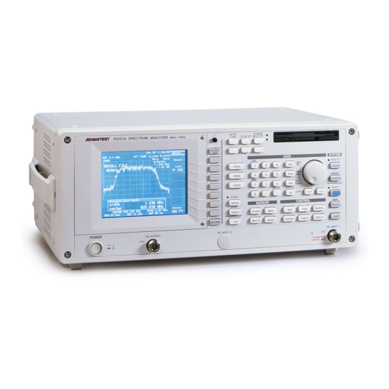
- Page 2 11DVANTEST ADVANTEST CORPORATION R3131 Series Spectrum Analyzer Operation Manual MANUAL NUMBER F O E -8311227F00 Applicable models R3131 R3131A First printing December 1, 1997 © 1 9 9 7 ADVANTEST CORPORATION All rights reserved. in Japan...
- Page 3 Note that Advantest bears absolutely no responsibility for the result of operations caused due to incorrect or inappropriate use of this instrument. If the equipment is used in a manner not specified by Advantest, the protection provided by the equipment may be impaired.
- Page 4 CAUTION: Indicates an item relating to possible damage to the product or instrument or relat- ing to a restriction on operation. • S a f e t y Marks on the Product The following safety marks can be found on Advantest products. A l 1ENTION - Refer to manual. Protective ground (earth) terminal.
- Page 5 1 1 1 1 Summary • R e p l a c i n g Parts with Limited Life The following parts used in the instrument are main parts with limited life. Replace the parts listed below after their expected lifespan has expired. Note that the estimated lifespan for the parts listed below may be shortened by factors such as the environment where the instrument is stored or used, and how often the instrument is used.
- Page 6 Environmental Conditions This instrument should be only be used in an area which satisfies the following conditions: • A n area free from corrosive gas • A n area away from direct sunlight • A dust-free area • A n area free from vibrations Figure-1 Environmental Conditions •...
- Page 7 R3131 Spectrum Analyzer Operation Manual Cautions on Using the R3131 Series The maximum safe input levels for the R3131 Series spectrum analyzers are listed below. A signal power exceeding these limits may damage internal parts such as the mixer. If there is a possibility that the input signal level may exceed the maximum safe input level, an external attenuator should be connected to the input port to attenuate the input signal.
- Page 9 EMC Directive 89/336/EEC in accordance with EN50081-1 and EN50082-1 and Low Voltage Directive 73/23/EEC in accordance with EN61010. ADVANTEST Corp. R O H D E & S C H W A R Z Tokyo, Japan and Sales GmbH Munich, Germany 3131.02...
- Page 11 R3131 Spectrum Analyzer Operation Manual PREFACE This manual provides the information necessary to check functionality, operate and program the R3131 Series Spectrum Analyzer. Be sure to read this manual carefully in order to use the spectrum analyzer safely. • Organization of this manual This manual consists of the following chapters: 1.
- Page 12 R3131 Spectrum Analyzer Operation Manual Preface • K e y notations in this manual Typeface conventions used in this manual. Panel keys: In bold type MKR, MEAS Soft keys: I n bold and italic type E x a m p l e : Normal Marker, Noise/Hz The 1/2, more and 2/2, more soft keys are designated by 1/2_more and 2/2_more in Chapter 2.
-
Page 13: Table Of Contents
R3131 Spectrum Analyzer Operation Manual TABLE OF CONTENTS 1 I N T R O D U C T I O N 1.1 P r o d u c t Description 1.2 Accessories 1.3 Operating Environment 1.3.1 Environmental Conditions 1.3.2 P o w e r Requirements 1.3.3 P o w e r Fuse 1.3.4 P o w e r Cable 1.4 System Checkout... - Page 14 R3131 Spectrum Analyzer Operation Manual Table of Contents 2.3.4 Measuring the VA Ratio 2.3.5 P a s s -Fail Judgments 2.3.6 Harmonic Distortion Measurements 2.3.7 Measurements Using TG (Option 74) 2.4 O t h e r Functions 2.4.1 U s i n g Floppy Disks 2.4.2 S a v i n g or Recalling Data 2.4.3 Outputting Screen Data 2.4.4 S e t t i n g Date and Time...
- Page 15 R3131 Spectrum Analyzer Operation Manual Table of Contents 3.4 S e t t i n g Values 3.4.1 S e t Resolution 3.4.2 S e t Values for RBW, VBW and SWP Time 3.4.3 F a c t o r y Defaults 3.4.4 D e f a u l t s Configuration Values 4 R E M O T E PROGRAMING 4.1 G P I B Remote Programming...
- Page 17 R3131 Spectrum Analyzer Operation Manual LIST OF ILLUSTRATIONS Page Title Operating Environment Replacing the Power Fuse Power Cable Connecting the Power Supply Cable Screen Display after Self Tests have Completed Self Test Screen 1-10 Screen Shown after Executing Self Test 1-11 Removing the Display Filter Front Panel...
- Page 18 R3131 Spectrum Analyzer Operation Manual List of Illustrations Page Title 2-44 2-38 Screen Display after Changing the VBW 2-45 2-39 The Trace after Averaging 2-46 2-40 Setup for Input Saturation 2-47 2-41 Screen Display without Saturation 2-48 2-42 Screen Display Showing Saturation 2-49 2-43 Setup for Measuring Harmonic Distortion...
- Page 19 R3131 Spectrum Analyzer Operation Manual List of Illustrations Page Title 2-90 Display after Data has been Saved to a File 2-86 2-91 Screen Display Showing File Protection Enabled 2-87 2-92 2-88 Screen Display Showing the Selected File 2-92 Screen Display Showing Recalled Data 2-89 2-93 2-90...
- Page 21 R3131 Spectrum Analyzer Operation Manual LIST OF TABLES Page Title Standard Accessories List Power Cable Options Power Supply Specifications Unit Key Settings 2-96 Recommended Compatible Printers Center Frequency Set Resolution vs. Frequency Span 3-53 3-53 Frequency Span Set Resolution vs. Frequency Span 3-54 Values for RBW, VBW and SWP Time (using AUTO) 3-55...
-
Page 23: N T R O D U C T I O N
• H o w to clean, store, and transport the spectrum analyzer 1.1 Product Description The R3131 Series is a spectrum analyzer that provides the user with highly stable spectrum analysis using the synthesized local method. The key features of the R3131 Series spectrum analyzer are listed below. -
Page 24: Accessories
Power cable A01403/A01441 N-BNC through connector JUG-201A/U R3131 Series Spectrum ER3131 Analyzer Operation Manual * 1: The cable supplied with the spectrum analyzer depends on what type (specified by model number above) was ordered when the spectrum analyzer was purchased. -
Page 25: Power Cable Options
R3131 Spectrum Analyzer Operation Manual 1.2 Accessories Table 1-2 Power Cable Options Rating, color Model number Plug configuration Standards and length (Option number) JIS: Japan 125 V at 7 A Straight: A 0 1 4 0 2 Black Law on Electrical Appliances 2 m (6 ft) Angled: A 0 1 4 1 2 / A 0 1 4 4 0 UL: United States of America... -
Page 26: Operating Environment
• A n area allowing unobstructed air flow The R3131 Series has an exhaust cooling fan on the rear panel and an exhaust vent on the bottom side toward the front. Never block these areas as the resulting internal temperature rise will affect measurement accuracy. -
Page 27: P O W E R Requirements
R3131 Spectrum Analyzer Operation Manual 1.3 Operating Environment The R3131 Series can be used safely under the following conditions: • Altitude: 2000m maximum above the sea level • Installation category II • Pollution degree 2 1.3.2 P o w e r Requirements The power supply specifications of the spectrum analyzer are listed in Table 1-3. - Page 28 R3131 Spectrum Analyzer Operation Manual 1.3 Operating Environment Pull out the fuse holder using a slotted head screwdriver. Fuse holder Check (and replace i f neces- sary) the power fuse and put it back into the fuse holder. Fuse (T5A compliant) Fuse holder fuse attached to the fuse holder.
-
Page 29: P O W E R Cable
R3131 Spectrum Analyzer Operation Manual 1.3 Operating Environment 1.3.4 P o w e r Cable A detachable power cable with a three-contact plug is included with the spectrum analyzer. The protective earth ground contact on the plug connects (through the power cable) to the accessible metal parts of the instrument. -
Page 30: System Checkout
R3131 Spectrum Analyzer Operation Manual 1.4 System Checkout 1.4 System Checkout This section describes the Self Test which must be performed when operating the spectrum analyzer for the first time. Follow the procedure below: CAUTION: W a i t at least 30 minutes after turning on the power before using to ensure accurate measurements. 1. -
Page 31: Screen Display After Self Tests Have Completed
R3131 Spectrum Analyzer Operation Manual 1.4 System Checkout Wed 1 0 Dec 1 9 9 7 REF 0 . 0 dBm ATT 10dB A _ w r t B _ b l n k 10dB/ Norm N o r m CENTER 1 . - Page 32 R3131 Spectrum Analyzer Operation Manual 1.4 System Checkout NOTE: Pressing SHIFT and 0 turns the Self Test mode on. In this mode, only the SHIFT, PRESET and COPY keys, and the currently displayed soft menu can be used. All other panel keys are disabled. 8.
-
Page 33: Cleaning, Storing And Transporting The Analyzer
R3131 Spectrum Analyzer Operation Manual 1.5 Cleaning, Storing and Transporting the Analyzer 1.5 Cleaning, Storing and Transporting the Analyzer 1.5.1 Cleaning Remove dust from the outside of the spectrum analyzer by wiping or brushing the surface with a soft cloth or small brush. -
Page 34: S T O R I N G
R3131 Spectrum Analyzer Operation Manual 1.5 Cleaning, Storing and Transporting the Analyzer 1.5.2 S t o r i n g Store the spectrum analyzer in an area which has a temperature from -20°C to +60°C. If you plan to store the spectrum analyzer for a long period (more than 90 days), put the spectrum analyzer in a vapor-barrier bag with a drying agent and store the spectrum analyzer in a dust-free location out of direct sunlight. -
Page 35: Replacing Parts With Limited Life
R3131 Spectrum Analyzer Operation Manual 1.6 Replacing Parts with Limited Life 1.6 Replacing Parts with Limited Life The R3I31 Series uses the following parts with limited life that are not listed in Safety Summary. Replace the parts listed below after their expected lifespan has expired. Part name Life Reed relay... -
Page 37: P E R At I O N
R3131 Spectrum Analyzer Operation Manual 2.1 Panel Description 2 O P E R AT I O N This chapter describes the following: • F r o n t and rear panel controls and connectors • Screen annotation • B a s i c operation •... - Page 38 R3131 Spectrum Analyzer Operation Manual 2.1.1 Front Panel (1) D i s p l a y Section ADYINIMIT R3131 SPECTRUM ANAL YZER saft-selie E l i E l e Control Description Liquid crystal display (LCD) Displays trace and measured data Active area Displays input data and measurement data Displays the function of each soft key (up to 7 at...
- Page 39 R3131 Spectrum Analyzer Operation Manual 2.1.1 Front Panel (2) P o w e r Switch/Connector Section M I M Y , m o o . 0 0 1 1 . • • • •111/40t ••111 Control Description POWER switch Turns the power on or off RF INPUT 1 connector N-type input connector son Analyzer input connector: Frequency range is 9 kHz...
- Page 40 R3131 Spectrum Analyzer Operation Manual 2.1.1 Front Panel (4) M E A S U R E M E N T Section C FREQ ( S P A N ( LEVEL (REPEAT) STOP SINGLE ( T G Control Description Used to set center frequencies FREQ key SPAN key Used to set frequency spans...
-
Page 41: Unit Key Settings
R3131 Spectrum Analyzer Operation Manual 2.1.1 Front Panel (5) D A T A Section DATA ( kHz ) = M C ENTER ( H z ) # 1 0 0 Control Description Numeric keys There are ten number keys (0 through 9) and a deci- (additional function keys) mal point key. - Page 42 R3131 Spectrum Analyzer Operation Manual 2.1.1 Front Panel (6) M A R K E R Section MARKER Description Control PK SRCH key Used to search for the peak point on the trace M K R key Used to display the marker MEAS key Used to set the measurement mode Used to obtain marker values so that they can be...
- Page 43 R3131 Spectrum Analyzer Operation Manual 2.1.1 Front Panel (7) C O N T R O L Section (DISPLAY) Control Description BW key Used to set the resolution bandwidth (RBW) and video bandwidth (VBW) TRIG key Used to set the trigger conditions PAS/FAIL key Used to set the conditions in the level window and check if those conditions have been met...
- Page 44 R3131 Spectrum Analyzer Operation Manual 2.1.1 Front Panel (8) S Y S T E M Section (-SY STM 0 REMOTE (LOCAL PRESET (CONFIG) o S H I F T SAVE (RECALL] ( COPY Control Description Used to disengage GPIB remote control LOCAL key Indicates the spectrum analyzer is in Remote mode REMOTE lamp...
- Page 45 R3131 Spectrum Analyzer Operation Manual 2.1.1 Front Panel (9) Miscellaneous Section Description Control Used to automatically display the maximum peak AUTO TUNE key Used to measure frequency as a counter COUNTER key POWER MEASURE key Used to make power measurements (Unused)
-
Page 46: Screen Annotation
R3131 Spectrum Analyzer Operation Manual 2.1.2 Screen Annotation 2.1.2 S c r e e n Annotation ----ADVANTEST 8 3 1 3 ec 3 1 0 : 2 8 : 3 6 Avg A 2 R E F - 2 0 . 0 dBm * A T T... - Page 47 R3131 Spectrum Analyzer Operation Manual 2.1.2 Screen Annotation Annotation Description Title Displays the title you have entered to distinguish the current data from other data Reference level Current reference level Amplitude scale Current amplitude scale graduation 7551 mode indicator Indicates that the input impedance is 7552 (nothing is displayed if the input impedance is 5052).
-
Page 48: R E A R Panel
R3131 Spectrum Analyzer Operation Manual 2.1.3 Rear Panel 2.1.3 R e a r Panel This subsection shows the rear panel and describes its terminals and connectors. e° Imo • • • • 1 1 O P T IRA T13 Figure 2-3 Rear Panel Control Description RS-232 connector... - Page 49 R3131 Spectrum Analyzer Operation Manual 2.1.3 Rear Panel Description Control 3-pin type AC power connector Holds the line fuse and one spare fuse which is supplied Fuse holder with the spectrum analyzer Fuse information Lists the line voltages and fuse requirements PROBE POWER terminal An accessory power supply for the probe, etc.
-
Page 50: B A S I C Operation
R3131 Spectrum Analyzer Operation Manual 2.2 Basic Operation 2.2 B a s i c Operation 2.2.1 Operating Menus and Entering Data You use panel keys and soft keys to operate the spectrum analyzer. When you press a panel key, a menu is usually displayed on the right side of the screen. - Page 51 R3131 Spectrum Analyzer Operation Manual 2.2.1 Operating Menus and Entering Data • Entering Data Using the Data Knob The data knob is used to enter data in units of predefined display resolution. This is convenient when making fine adjustments to data which has already been entered. Example: T o set the reference level to 0.5 dBm using the data knob, turn the knob clockwise.
- Page 52 R3131 Spectrum Analyzer Operation Manual 2.2.1 Operating Menus and Entering Data • 1/2_more and 2/2_more Pressing 1/2_more shows the rest of the soft key menu (those items not currently visible). Like- wise, pressing 2/2_ more at the bottom of this display returns to the top of the soft key display (the previous set of items).
-
Page 53: Displaying Spectrums And Operating The Markers
R3131 Spectrum Analyzer Operation Manual 2.2.2 Displaying Spectrums and Operating the Markers 2.2.2 Displaying Spectrums and Operating the Markers The following example measures the frequency difference between the peak point and a point 3 dB levels lower, and another frequency difference between the peak point and a point 60 dB levels lower. Power on NOTE: T o take accurate measurements, use the spectrum analyzer within the speci- fied temperature range, and wail at least 30 minutes after turning the power... -
Page 54: Factory Defaults Screen
The Cal menu used with calibrations is displayed. 8. Press Cal Sig Level ON/OFF. Cal Sig Level ON/OFF is turned on, and the calibration signal is output. ADVANTEST R3131 10 Dec 1997 REF 0 . 0 d8m 10dB A _ w r t B _ b l n k odp,_ "... - Page 55 The current center frequency is displayed in the active area, and the Freq menu used to select the frequency type appears on the right. Wed 1 0 Dec 1997 ADVANTEST R3131 Freq ATT 10dB A _ w r t B _ b l n k REF 0 .
-
Page 56: Measuring Settings Screen
The current reference level is displayed in the active area, and the Level menu used for setting the level appears on the right. 14. Press 1, 0, MHz(-dBm). A reference level of -10 dBm is set. ADVANTEST R3131 Wed 10 Dec 1997 Level REF - 1 0 . 0 dBm... - Page 57 R3131 Spectrum Analyzer Operation Manual 2.2.2 Displaying Spectrums and Operating the Markers ADVANTEST R3131 Wed 1 0 Dec 1997L e v e l REF - 1 0 . 0 dBm ATT 10dB A _ w r t B _ b l n k...
-
Page 58: Frequency Difference Between The Peak Point And A Point 3 Db Levels Down
R3131 Spectrum Analyzer Operation Manual 2.2.2 Displaying Spectrums and Operating the Markers ADVANTEST R3131 Wed 1 0 Dec 1997 Marker(1) REF - 1 0 . 0 dBm ATT 10dB A _ tort B _ b l n k 10dB/ Norm N o r m N o r m a l... -
Page 59: Measuring Window And The Display Line
R3131 Spectrum Analyzer Operation Manual 2.2.3 Measuring Window and the Display Line 2.2.3 Measuring Window and the Display Line This section describes the measuring window which is used to display measurements within a limited area, and the display and reference lines which are used to compare traces. Power on 1. -
Page 60: Calibration Signal Output
R3131 Spectrum Analyzer Operation Manual 2.2.3 Measuring Window and the Display Line Wed 1 0 Dec 1997 ADVANTEST R3131 ATT 10dB A _ w r t B _ b l n k REF 0 . 0 dBm 10031_ Norm N o r m... -
Page 61: Activating The Display Line
8. M o v e the display line vertically so that it aligns with the peak on the right side by turning the data knob. This makes it easier to compare trace levels. ADVANTEST R3131 Thu 2 5 Jun 1998D i s p l a y REF - 1 0 . 0 dBm... - Page 62 R3131 Spectrum Analyzer Operation Manual 2.2.3 Measuring Window and the Display Line ADVANTEST R3131 2 5 Jun 1998D i s p l a y REF - 1 0 . 0 dBm A T T 10d8 A _ w r t Et_blnk piay , Norm , N o r m "...
-
Page 63: Screen Display Showing The Measuring Window
R3131 Spectrum Analyzer Operation Manual 2.2.3 Measuring Window and the Display Line ADVANTEST R3131 Thu 2 5 Jun 1998 fleas WOO ATT 10dB A _ w r t B _ b l n k REF - 1 0 . 0 dBm Norm N o r m Window lOdB/. -
Page 64: Measuring Frequency Using Counter
R3131 Spectrum Analyzer Operation Manual 2.2.4 Measuring Frequency Using Counter 2.2.4 Measuring Frequency Using Counter The counter function measures the signal frequency at the marker with high accuracy. You do not have to precisely position the marker on the peak you wish to measure however you should note that the displayed amplitude value corresponds to the marker position. -
Page 65: Calibration Signal Output Screen
R3131 Spectrum Analyzer Operation Manual 2.2.4 Measuring Frequency Using Counter Cal Sig Level ON/OFF is turned on, and the calibration signal is output. ADVANTEST R3131 Wed 1 0 Dec 1997C a l ATT 10dB A _ w r t REF 0 . 0 dBt... -
Page 66: Frequency Counter Measurement (Resolution: 1 Khz)
6. P r e s s COUNTER. The Counter menu (used for setting the frequency counter resolution) and the Frequency Counter window are displayed. The default resolution is 1 kHz. ADVANTEST R3131 Wed 1 0 Dec 1997 Counter REF 0 . 0 dBm ATT 10dB A _ w r t _.Norm N o r m... -
Page 67: A U T O Tuning
This sets the frequency span in preparation for auto-tuning. 4. P r e s s SPAN, 1, 0, 0 and kHz. A frequency span of 100 kHz is set. ADVANTEST R3131 Wed 1 0 Dec 1997S o o n REF 0 . 0 dem... - Page 68 W i t h this function, the m a x i m u m peak is automatically displayed. T h e reference level is set to the tuned peak level under these conditions. ADVANTEST R3131 Wed 1 0 Dec 1997S p a n REF - 9 .
-
Page 69: Tracking Operations
R3131 Spectrum Analyzer Operation Manual 2.2.6 Tracking Operations 2.2.6 Tr a c k i n g Operations Tracking operations consist of signal tracking (which is useful for measuring a signal whose frequency is variable) and continuous peak search functions. Power on 1. -
Page 70: Signal Tracking Screen
Signal tracking is turned on. The detected peak frequency is always set as the cen- ter frequency even if the input signal frequency varies. ADVANTEST R3131 Wed 1 0 Dec 1997 Marker(1) ATT 10dB A _ w r t B _ b l n k REF 0 . -
Page 71: Continuous Peak Search Screen
The Cont peak search is turned on. A peak is detected in each sweep and the marker is always moved to that peak even if the input signal frequency varies. ADVANTEST R3131 Wed 1 0 Dec 1997P e d a l ) REF 0 . -
Page 72: Uncal Messages
R3131 Spectrum Analyzer Operation Manual 2.2.7 UNCAL Messages 2.2.7 U N C A L Messages Accurate measurements cannot be made if there is an inappropriate combination of parameters when mea- suring the resolution bandwidth (RBW), the video bandwidth (VBW), the frequency span, the sweep time and so on (the parameters for these measurements affect each other). -
Page 73: Measuring Settings Screen
R3131 Spectrum Analyzer Operation Manual 2.2.7 UNCAL Messages ADVANTEST R3131 Wed 1 0 Dec 1997S p a n REF 0 . 0 dBm ATT 10dB A _ w r t B _ b l n k 10d0/_. Norm N o r m F u l l Span SPAN 10.00 MHz... - Page 74 An accurate measurement can be made now that the video bandwidth has been set to 100 kHz. Note that there is no longer an UNCAL message on the screen. ADVANTEST R3131 Wed 10 Dec 1997 REF 0 . 0 dBm...
-
Page 75: Separating Two Signals
R3131 Spectrum Analyzer Operation Manual 2.2.8 Separating Two Signals 2.2.8 Separating Two Signals This section describes how RBW should be set to properly observe adjacent signals using the spectrum analyzer. Setup 1. Connect the signal generators as shown in Figure 2-31. R3131 Spectrum analyzer Signal generator (SG1) g..Q:si... - Page 76 The spectrums are not fully separated because the RBW default setting is 100 MHz. As a result, the display shows only one input signal even though there are actually two. ADVANTEST 83131 Thu 11 D e c 1997L e v e l REF - 1 0 . 0 dBm...
- Page 77 The RBW is set to 30 kHz. Two peaks are now discernible but they are still not clearly separated. ADVANTEST R 3 1 3 1 11 D e c 1 9 9 7 B REF - 1 0 . 0 a m...
- Page 78 R3131 Spectrum Analyzer Operation Manual 2.2.9 Dynamic Range 2.2.9 D y n a m i c Range The dynamic range can be increased by reducing the noise level, which is accomplished by narrowing the resolution bandwidth. The noise level can be further reduced by setting the video bandwidth (VBW) to approximately 1/10 of the resolution bandwidth (RBW).
-
Page 79: Screen Display Prior To Changing The Rbw
A frequency span of 100 MHz is set. 7. P r e s s LEVEL, 4, 0 and MHz(-dBm). The reference level is set to -40 dBm. ADVANTEST R3131 F r i 1 9 Dec 1997L e v e l REF - 4 0 . 0 dBm... -
Page 80: Screen Display After Changing The Rbw
R3131 Spectrum Analyzer Operation Manual 2.2.9 Dynamic Range ADVANTEST R3131 1 9 Dec 1997 REF - 4 0 . 0 dBm A T T 10dB A _ w r t B _ b l n k Norm N o r m R B W... -
Page 81: Dynamic Range
10. Press TRACE, 1/2_more and A VG A. AVG A (with a default setting of 20) has reduced the noise level considerably. ADVANTEST R3131 F r i 1 9 Dec 1997A v g A REF - 4 0 . 0 dBm A T T... -
Page 82: Input Saturation
R3131 Spectrum Analyzer Operation Manual 2.2.10 Input Saturation 2.2.10 I n p u t Saturation After a signal being sent to the input mixer reaches a certain level, the displayed value is not proportional to the signal input because of saturation. An input level producing a I db error due to saturation is defined as the gain compression. -
Page 83: Screen Display Without Saturation
The Attenuator level is set to 0 dB. Under these conditions, the input level at the mixer is -16 dBm, and the measure- ment is correct without saturation. ADVANTEST R3131 Thu 11 Dec 1997 Level REF - 1 0 . 0 dBm... -
Page 84: Screen Display Showing Saturation
9. S e t SG I level to +10 dBm. Under these conditions, the input level for the mixer is +4 dBm, and the right hand signal level is reduced due to saturation caused by gain compression. ADVANTEST R3131 Thu 11 Dec 1997 Level REF - 1 0 . -
Page 85: Harmonic Distortion
R3131 Spectrum Analyzer Operation Manual 2.2.11 Harmonic Distortion 2.2.11 Harmonic Distortion Harmonic distortion is produced by non-linearity from the input mixer if the input exceeds a certain limit. As a result, spurious signals which do not come from the input signal may be observed. Setup 1. -
Page 86: Screen Display Showing Harmonic Distortion
When the attenuator is set to 10 dB (default setting), and the mixer input is -10 dBm 0 dBm - 10 dB), harmonic distortion occurs. ADVANTEST R3131 Thu 11 Dec 1997 ATT 10dB A _ w r t B _ b l n k REF 0 . -
Page 87: Screen Display Showing Reduced Harmonic Distortion
2.2.11 Harmonic Distortion 9. P r e s s LEVEL, A77' AUTO/MNL, 3, 0 and GHz (dB). The attenuator level is set to 30 dB. ADVANTEST R3131 Thu 11 Dec 1997L e v e l REF 0 . 0 dBm... -
Page 88: Intermodulation
R3131 Spectrum Analyzer Operation Manual 2.2.12 Intermodulation 2.2.12 Intermodulation This section describes how to set up the attenuator (ATT) when using a spectrum analyzer which is receiv- ing more than one input signal. When signals with an excess amplitude are input, spurious signals produced by intermodulation are dis- played. -
Page 89: Screen Display Showing Intermodulation Distortion
-20 dBm (= -10 dBm - 10 dBm). Since the mixer level exceeds the distortion limit, spurious peaks (3 and 4) appear in addition to the normal peaks (1 and 2). ADVANTEST R3131 Thu 11 Dec 1997S p a n REF 0 . 0 dBm ATT 10dB A _ w r t B _ b l n k 10010/.. -
Page 90: Screen Display Without Intermodulation Distortion
R3131 Spectrum Analyzer Operation Manual 2.2.12 Intermodulation ADVANTEST R3131 11 D e c 1997L e v e l REF 0 . 0 dem * A T T 30d6 A _ w r t I POW_ , - - ! 1 9 7 1 9 - - 1 4 9 7... -
Page 91: Calibration
NOTE: D o not use any input signals when performing a calibration. 1. P r e s s SHIFT and 7 (CAL). The Cal menu used for calibration appears. ADVANTEST R3131 Thu 11 D e c 1997 ATT 10dB A _ w r t B _ b l n k REF 0 . -
Page 92: Entering User-Definable Antenna Correction Data
R3131 Spectrum Analyzer Operation Manual 2.2.14 Entering User-definable Antenna Correction Data 2.2.14 Entering User-definable Antenna Correction Data You can define your own antenna correction data in addition to the four regular types of antenna correction data. This section describes how to do this. Creating a correction data table Save an empty correction data table to a floppy disk using the following procedure. -
Page 93: Editing The Correction Data Table
R3131 Spectrum Analyzer Operation Manual 2.2.14 Entering User-definable Antenna Correction Data E O M File01 dat ADVANTEST R31 31 SYSID 31 31000X1 08 TITLE *ADVANTEST R31 31 DATE 1 997/1 2/1 9 17:38 <ANT CORR> ! 5000000001 — 4 5f 800000000: — 35 1000000009i —... -
Page 94: Measurement Examples
2.3 Measurement Examples 16. Press User Ant Corr. The edited data in the correction data table is displayed. ADVANTEST R3131 Wed 1 0 Dec 1997 User C o r r REF 1 0 7 . 0 dBpV/m ATT 10dB A _ w r t 194$/__ N o r m "... -
Page 95: Setup For Measuring The Channel Power
R3131 Spectrum Analyzer Operation Manual 2.3.1 Measuring the Channel Power R3131 Spectrum analyzer Unit under test Antenna terminal RF INPUT 1 connector External attenuator Attenuation: 10 dB) Figure 2-52 Setup for Measuring the Channel Power Power on 2. T u r n the power on. Setting the unit under test 3. -
Page 96: Setting The Offset Level
The offset level is set to 10 dB. The measurement values, including values for the external attenuator, are now displayed. ADVANTEST R3131 Mar 20 1 4 . 0 5 . 3 3 L e v e l REF 2 0 . 0 dBm ATT 20dB A _ w r t B _ b l n k - . -
Page 97: Setting The Measuring Window
2.3.1 Measuring the Channel Power 13. Press CH BW POS/WD, 3, 0, 0 and kHz. The channel width is set to 300 kHz. ADVANTEST R3131 Thu 25 Jun 1998 CH Power REF 2 0 . 0 dBm ATT 20dB A _ w r t B _ b l n k... -
Page 98: Measuring The Occupied Bandwidth (Obw)
R3131 Spectrum Analyzer Operation Manual 2.3.2 Measuring the Occupied Bandwidth (OBW) 2.3.2 Measuring the Occupied Bandwidth (OBW) The occupied bandwidth can be calculated from the measured screen data using the OBW function. In this operation, the ratio of the OBW to the total power ranges from 10.0 to 99.8%. The initial setting is 99%. Measurement conditions: This example shows how to measure the occupied bandwidth for a unit similar to PHS outputting a fre- quency of 1895.15 MHz, an OBW of 288 kHz and a level of 20 dBm. -
Page 99: Setting The Detector Mode
Setting the detector mode 7. Press TRACE, Detector and Posi. The trace is set to positive detector mode. ADVANTEST R3131 Mar 20 1 5 . 1 5 . 1 2 Trc D e t A REF 0 . 0 dem... - Page 100 R3131 Spectrum Analyzer Operation Manual 2.3.2 Measuring the Occupied Bandwidth (OBW) ADVANTEST R3131 Mar 2 0 1 5 . 1 6 . 5 8 O B W REF 0 . 0 dBm ATT 10dB A _ w r t B _ b l n k...
-
Page 101: Measuring Adjacent Channel Leakage Power (Acp)
R3131 Spectrum Analyzer Operation Manual 2.13 Measuring Adjacent Channel Leakage Power (ACP) 23.3 Measuring Adjacent Channel Leakage Power (ACP) The adjacent channel leakage power (ACP) function calculates the ratio of the power in the specified band- width obtained by integration to the total power (obtained from the data on the screen). Measurement conditions: This example shows how to measure the ACP at a specified bandwidth of 192 kHz and an offset of 600 kHz or 900 kHz for a unit under test (complying with PHS Satndards) PHS outputting a frequency of... - Page 102 R3131 Spectrum Analyzer Operation Manual 2.3.3 Measuring Adjacent Channel Leakage Power (ACP) Initialization This resets the current settings to the factory defaults. 4. Press SHIFT and CONFIG (PRESET). The default settings have now been reset. Setting the measurement conditions This changes the analyzer settings so that the input signal is displayed more clearly. 5.
-
Page 103: Setting The Specified Bandwidth
R3131 Spectrum Analyzer Operation Manual 2.3.3 Measuring Adjacent Channel Leakage Power (ACP) ADVANTEST R3131 Thu 2 5 Jun 1998 REF 0 . 0 dBm ATT 10dB A _ w r t B _ b l n k 1003/ Posi N o r m A C P... -
Page 104: Measurements Using The Acp Graph Method
R3131 Spectrum Analyzer Operation Manual 2.3.3 Measuring Adjacent Channel Leakage Power (ACP) CAUTION: I. O n l y ACP (adjacent) can be measured when Channel Spacing 2 ON/OFF is turned off 2. T h e frequency span is automatically changed to an appropriate value if its value is less than the required one (this incorrect frequency span may have been caused by either the channel spacing or the specified bandwidth). - Page 105 R3131 Spectrum Analyzer Operation Manual 2.3.3 Measuring Adjacent Channel Leakage Power (ACP) Setting the measurement conditions This changes the analyzer settings so that the input signal is displayed more clearly. 5. P r e s s FREQ, 1, 8, 9, 5, ., 1, 5 and MHz. A center frequency of 1895.15 MHz is set.
- Page 106 R3131 Spectrum Analyzer Operation Manual 2.3.3 Measuring Adjacent Channel Leakage Power (ACP) ADVANTEST R3131 Thu 2 5 Jun 1998A C P REF 0 . 0 dBm 10dB A _ w r t 10d8/ N o r m A C P...
-
Page 107: Measuring The Va Ratio
R3131 Spectrum Analyzer Operation Manual 2.3.4 Measuring the VA Ratio 23.4 Measuring the VA Ratio The VA ratio is the ratio between the video signal and the audio signal used in television carriers. When the audio signal level is too low in relation to the video signal level, bass sound is produced. In the opposite situation, the video signal has interference caused by cross modulation from the audio signal. - Page 108 9. Press TRACE, I/2_more, and Max Hold. Perform the Max hold function for approximately 1 minute to allow for level fluctuations. ADVANTEST R3131 1 9 Dec 1997 Trc A(2) REF 1 0 7 . 0 dB,V A T T 10d6 A _ , a x B _ b l n k Posi P o s i Max Hold AVG A ▶...
-
Page 109: Measuring The Video Carrier Level
R3131 Spectrum Analyzer Operation Manual 2.3.4 Measuring the VA Ratio ADVANTEST R 3 1 3 1 1 9 D e c 1 9 9 7 M a r k e r ( 1 ) REF 1 0 7 . 0 d B AV... - Page 110 R3131 Spectrum Analyzer Operation Manual 2.3.5 Pass-Fail Judgments 2.3.5 P a s s -Fail Judgments pass (shown as When a marker appears within the level window, the PASS/FAIL judgment result is a confined area PASS). The measuring window can be used to make a high speed measurement within when convenient.
- Page 111 ADVANTEST R3131 Wed 10 Dec 1997 Pass- F a i l REF 0 .
-
Page 112: Measuring Window Screen
R3131 Spectrum Analyzer Operation Manual 2.3.5 Pass-Fail Judgments ADVANTEST R3131 Wed 1 0 Dec 1997 Pass- F a i l REF 0 . 0 dBm ATT 10dB A _ w r t B _ b l n k Od8/ Norm. N o r m Pass- F a i l... -
Page 113: Pass-Fail Judgments
R3131 Spectrum Analyzer Operation Manual 2.3.5 Pass-Fail Judgments Performing the window sweep 13. Press Window Sweep ON/OFF. A window sweep is performed. The sweep is completed more quickly because only the area within the measuring window is swept. 2-77... -
Page 114: Harmonic Distortion Measurements
R3131 Spectrum Analyzer Operation Manual 2.3.6 Harmonic Distortion Measurements 2.3.6 Harmonic Distortion Measurements This section describes a method for quickly measuring harmonic distortion using the step keys. Measurement conditions: This example shows how to measure harmonic distortion for a unit outputting a frequency of 800 MHz, a level of -30 dBm and a non-modulated signal. -
Page 115: Measuring The Fundamental Wave
T h e m a r k e r is d i s p l a y e d on the peak. T h e l e v e l d i s p l a y e d i n the m a r k e r area is recorded as the fundamental wave level. ADVANTEST R3131 Thu 11 Dec 1997F r e q REF - 3 0 . -
Page 116: Measuring The Harmonic Distortion
The har- monic distortion is the difference between the higher harmonic wave and the fundamental wave levels. ADVANTEST R3131 Thu 11 D e c 1997 Freq REF - 3 0 . 0 dBm A T T... -
Page 117: Measurements Using Tg (Option 74)
R3131 Spectrum Analyzer Operation Manual 2.3.7 Measurements Using TG (Option 74) 2.3.7 Measurements Using TG (Option 74) Band-pass filter characteristics with a passband of approximately 270 MHz, are measured (both the inser- tion loss and bandwidth are measured). CAUTION: U N C A L messages, displayed when measuring frequency characteristics using this function, do not affect measurement results. - Page 118 The output level of the tracking generator is set to 0 dBm. 9. Press TG and Execute Normalize. The normalization calibration is performed. ADVANTEST R3131 F r i 2 8 Aug 1998 REF 0 . 0 dBm ATT 10d8 A _ w r t B _ b l n k 2d8/ _ Norm "...
-
Page 119: Connecting The Unit Under Test
R3131 Spectrum Analyzer Operation Manual 2.3.7 Measurements Using TO (Option 74) Connecting the unit under test 10. Connect the unit under test between TG OUTPUT and RF INTPUT1 as shown in Figure 2-79. R3131 Spectrum analyzer 1701=1c3.2.._ = g = 1 0 0 0 0 0 0... -
Page 120: Other Functions
R3131 Spectrum Analyzer Operation Manual 2.4 Other Functions ADVANTEST R3131 F r i 2 8 Aug 1998S w e e p REF 0 . 0 dem ATT 10dB A _ w r t B _ P l n k Norm N o r m SWP Time ..?dE3/. - Page 121 R3131 Spectrum Analyzer Operation Manual 2.4.1 Using Floppy Disks disks can be accessed from personal computers. The following floppy disk formats can be used: 3.5-inch DD 720KB, HD 1.2 MB and 1.44MB (MS-DOS format compatible). Write-protecting the Floppy Disk This prevents you from accidentally initializing or overwriting a floppy containing previ- ously saved data.
- Page 122 R3131 Spectrum Analyzer Operation Manual 2.4.1 Using Floppy Disks (2) Inserting Floppy Disks 1. Insert a floppy disk into the floppy disk drive with the label surface up. (3) Removing Floppy Disks 1. Ve r i f y that the lamp on the drive is not lit and then remove the disk. CAUTION: D o not remove the floppy disk while the drive lamp is lit, since this indi- cates thatfloppy disk is being accessed I f you remove the disk while the disk is being accessed, you may damage the data contained on the disk.
- Page 123 R3131 Spectrum Analyzer Operation Manual 2.4.1 Using Floppy Disks ADVANTEST R3131 Wed 1 0 Dec 1997F . D i s k REF 0 . 0 dBm ATT 10dB A _ w r t B _ b l n k Norm N o r m Format F.Disk...
-
Page 124: S A V I N G Or Recalling Data
This selects either RAM (internal memory) or FD (floppy disk) as the file desti- nation. CAUTION: F D cannot be selected if a floppy disk is not present in the floppy disk drive. ADVANTEST R3131 1 0 Dec 1997 Save REF 0 . 0 dBm... - Page 125 Trc Lvl ON/OFF level values for the trace data (available when trace data is being saved) ADVANTEST R3131 2 8 Aug 1998 Save I t e m REF 0 . 0 d8m 10d9 A_vort B _ b l n k tow__________14.97k11.9!7!% Setup...
-
Page 126: Display After Data Has Been Saved To A File
R B W 300 kHz V B W 100 kHz S W P 5 0 ms Delete FILE L I S T k F D : / S V F. : 0 LIMMAMEM ADVANTEST R3131 J<FILE00.DAT> J97/12/10 1 9 : 0 7... -
Page 127: Screen Display Showing File Protection Enabled
R B O J I 300 kHz V B W 100 kHz S W P SO ms Delete FILE L I S T ( F D : R C L ) <FILE00.DAT> 04111011111 ADVANTEST R3131 97/12/10 19:07 RO 1070S Bytes Setup: ON... -
Page 128: Screen Display Showing The Selected File
R B W 300 kHz V B W 1 0 0 k H z S W P 5 0 ms FILE L I S T (FD:/SVRCL) OWN*14.111 ADVANTEST R3131 <FILE00.DAT> 9 7 / 1 2 / 1 0 1 9 : 0 7... - Page 129 CENTER 3 0 . 0 0 MHz S P A N 2 0 . 0 0 MHz - - *RBM 300 kHz * V B W 100 kHz * S W P SO ms Delete FILE L I S T CFL:/'L•1RCL) 10013)111111. ADVANTEST R3131 <FILE00.DAT> 97/12/10 2 2 : 2 8 R W 10713 Bytes...
- Page 130 2.4.2 Saving or Recalling Data Deleting the data 4. P r e s s Delete. The data in the selected file is deleted. ADVANTEST R3131 Wed 1 0 Dec 1997 Save REF 0 . 0 dBm ATT 10dB A _ w r t B _ b l n k...
-
Page 131: Outputting Screen Data
The Copy Dev menu used for selecting the screen data destination appears. 3. P r e s s F.Disk. Floppy disk is chosen as the destination for the screen data. ADVANTEST R3131 2 0 16:00:11 c o p , D e v REF 0 . 0 dBm... - Page 132 R3131 Spectrum Analyzer Operation Manual 2.4.3 Outputting Screen Data CAUTION: D o not remove the floppy disk while the access lamp is lit, since the floppy disk is being accessed. I f you remove the disk while the disk is being accessed you may damage the data on the disk.
- Page 133 3. P r e s s Printer. The attached printer is selected as the destination for the screen data. Wed 1 0 Dec 1997 ADVANTEST R3131 Copy Dev REF 0 . 0 can ATT 10dB A _ w r t B _ b l n k...
- Page 134 R313I Spectrum Analyzer Operation Manual 2.4.3 Outputting Screen Data ADVANTEST R3131 2 0 16:01 :12—F r i n t e r REF 0 . 0 dBm 10dB A _ w r t 13_blnk P r i n t c o m l- C._.__._.___...
-
Page 135: Setting Date And Time
R3131 Spectrum Analyzer Operation Manual 2.4.4 Setting Date and Time 2.4.4 Setting Date and Time This section explains how to set the date and time for the spectrum analyzer. In the following example, a time and date of 1:35 pm Dec 10 1997 is set. Setting the date and time 1. -
Page 136: Screen Showing The Date Being Set
R3131 Spectrum Analyzer Operation Manual 2.4.4 Setting Date and Time ADVANTEST R3131 1 0 Dec 1997 Time/bate REF 0 . 0 dBm 10dB A _ w r t B _ b l n k 10dB/ N o r m Year ;DAY... - Page 137 R3131 Spectrum Analyzer Operation Manual 2.4.4 Setting Date and Time Setting the date display format 7. Press Date Mode MDH/DMY. Toggles between MDH and DMY format each time you press the key. MDH: Displays Month/Day/Hour. For example: Dec 10 13:35:00 DMY: Displays Day of the week, Date/Month/Year.
-
Page 139: M E N U Index
R3131 Spectrum Analyzer Operation Manual 3.1 Menu Index 3 R E F E R E N C E 3.1 M e n u Index Pages Operation Key Pages Operation Key % AM Meas ON/OFF 3-10, 3-39 3-8, 3-30 Channel Spacing 2 ON/OFF 3-6, 3-21 3-6, 3-21 Clear... - Page 140 R3131 Spectrum Analyzer Operation Manual 3.1 Menu Index Execute Self Test 3-35 3-11, 3-44 Exit MKR ( w h e n using the delta marker) 3 - 9 3-11, 3-44 3-12, 3-52 MKR -4 (when using the normal marker) 3 - 9 F.Disk 3-9, 3-34, 3-5, 3-16...
- Page 141 R3131 Spectrum Analyzer Operation Manual 3.1 Menu Index 3-7, 3-24 Printer Config 3-5, 3-16 Start 3-7, 3-24 Stop Protect 3-11, 3-43 3-5, 3-17 Stop Bit 1/2 Pwr Meas Off 3-10, 3-38 3-12, 3-51 Store A(B) to B(A) 3-7, 3-22 3-12 RBW 120kHz 3-7, 3-22 SWEEP...
- Page 142 R3131 Spectrum Analyzer Operation Manual 3.2 Menu Map 3.2 M e n u Map Abort ( COPY)) Abort AUTO TUNE RBW AUTO/MNL VBW AUTO/MNL Auto All CAL \ CAL ( 7 ) ) Cal All Total Gain Each Item IF Step Amp Freq Corr ON/OFF RBW Switch Cal Con ON/OFF...
- Page 143 R3131 Spectrum Analyzer Operation Manual 3.2 Menu Map CONFIG —Copy Dev [Printer Printer Config F. Disk F. Disk Config Reset File No. GPIB Set Up RS232 [ P r i n t CMD PCUESCP/ESCP-R Time/Date — ' C o p y Mode GRAY/ B/W 1/2, more Copy Size HALF/FULL ▶...
-
Page 144: Menu Map
R3131 Spectrum Analyzer Operation Manual 3.2 Menu Map C O U N T E R Res 11:11z Res 100Hz Res 10Hz Res 1Hz Counter Off C D I S P L A Y ) Display Line ON/OFF Window POS/WD Ref Line ON/OFF Window SRT/STP Meas Window Zoom In... - Page 145 R3131 Spectrum Analyzer Operation Manual 3.2 Menu Map EMC ) ( 1 1 Detector Mode [ R B W Auto Field RBW 9kHz Peak RBW 120kHz Sound Normal T R 1 7 2 2 UHALP9107 BBA9106 EMC03142 User Ant Corr —...
- Page 146 R3131 Spectrum Analyzer Operation Manual 3.2 Menu Map ( LOCAL Noise/Hz dBm/Hz XdB Down dfittV/ •NI Hz 3rd Order Meas dBe/Hz % AM Meas ON/OFF Noise/Hz Off XdB Down XdB Left XdB Right MKR Read DLT/LFT/RHT Cont Down ON/OFF — Next Peak Normal Marker Next Peak Left Delta Marker...
- Page 147 R3131 Spectrum Analyzer Operation Manual 3.2 Menu Map M K R —.)) ( w h e n using the normal marker) —MKR --> CF MKR --> R e f Peak -4 C F Peak -4 R e f MKR Trace 1/2, more MKR —>...
- Page 148 R3131 Spectrum Analyzer Operation Manual 3.2 Menu Map POWER MEASURE — CH Power ON/OFF Channel Power CH BW POS/WD Total Power CH BW SRT/STP Average Power Carrier Power Pwr Meas Off OBW ON/OFF 013W OBW % ACP ON/OFF Channel Spacing 1 Channel Spacing 2 ON/OFF Channel Band WD Graph ON/OFF...
- Page 149 R3131 Spectrum Analyzer Operation Manual 3.2 Menu Map SAVE SAVE [RECALL Save — Setup ON/OFF Save Item ON/OFF Protect Corr ON/OFF Delete Corr ON/OFF Device RAM/FD Lvl ON/OFF SELF TEST ( Execute Self Test Exit C SPAN Full Span Zero Span Peak Zoom Last Span 3-11...
- Page 150 R3131 Spectrum Analyzer Operation Manual 3.2 Menu Map ( SWEEP ) SWP Time AlUTO/MNL Auto All Gate Sig External ON/OFF (Option 74) TG Level Execute Normalize Norm Corr ON/OFF Ref Line Position Freq Adj Auto Freq Adj Manual TG Off TRACE ) Write A (B) Normal...
-
Page 151: M E N U Function Descriptions
R3131 Spectrum Analyzer Operation Manual 3.3 Menu Function Descriptions 3.3 M e n u Function Descriptions This section describes all panel keys and any associated menus displayed when they are pressed. 3.3.1 A U T O TUNE Key (Auto Tuning) Used to display the maximum peak using the current conditions as a target span. -
Page 152: B W Key (Bandwidth)
R3131 Spectrum Analyzer Operation Manual 3.3.2 BW Key (Bandwidth) 33.2 B W Key (Bandwidth) This section describes the menu displayed when the BW key is pressed. From this menu, you can change the parameters for the resolution bandwidth (RBW) and the video bandwidth (VBW) as required. RBW AUTO/MNL the video bandwidth between AUTO and MNL. -
Page 153: C A L Key (Calibration)
R3131 Spectrum Analyzer Operation Manual 3.3.3 CAL Key (Calibration) 3.3.3 C A L Key (Calibration) This section describes the menu displayed when the SHIFT key and the 7 (CAL) key are pressed. Cal All Executes all calibration routines. Total Gain Measures the absolute error using a resolution bandwidth of 300 kHz, and the calibration signal output of both -15dBm and ldB/ DIV. -
Page 154: Config Key (Configuration)
R3131 Spectrum Analyzer Operation Manual 3.3.4 CONFIG Key (Configuration) 3.3.4 C O N F I G Key (Configuration) This section describes the menu displayed when the CONFIG key is pressed. Copy Dev the Copy Dev menu which is used to select the device for outputting the screen data. - Page 155 R3131 Spectrum Analyzer Operation Manual 3.3.4 CONFIG Key (Configuration) Set Up RS232 the RS-232 menu used to set the conditions used with the RS-232 interface. Baud Rate you to set the transfer rate in bauds. Length 7/8 T o g g l e s between 7-bit and 8-bit data lengths.
-
Page 156: C O P Y Key (Hard Copy)
R3131 Spectrum Analyzer Operation Manual 3.3.5 COPY Key (Hard Copy) 3.3.5 C O P Y Key (Hard Copy) Sends the screen data to the destination selected by the Copy Dev item in the Config (1) menu. (Note there is no menu associated with this panel key.) *To abort printing: Pressing SHIFT, COPY and Abort aborts the printing currently taking place. -
Page 157: Counter Key (Frequency Counter)
R3131 Spectrum Analyzer Operation Manual 3.3.6 COUNTER Key (Frequency Counter) 3.3.6 C O U N T E R Key (Frequency Counter) Activates the Frequency counter mode and displays the associated menu. The current measurement fre- quency is also displayed. Res 1kHz the frequency counter resolution to 1kHz. -
Page 158: Display Key (Line And Window)
R3I31 Spectrum Analyzer Operation Manual 3.3.7 DISPLAY Key (Line and Window) 3.3.7 D I S P L AY Key (Line and Window) This section describes the menu displayed when the DISPLAY key is pressed. Toggles the display line indication on or off. The display line is Display Line ON/OFF used as a base line when comparing trace levels. - Page 159 R3131 Spectrum Analyzer Operation Manual 3.3.7 DISPLAY Key (Line and Window) Window Off the measuring window. Displays the Title (1) menu. From this mode, you can set the title Change Title used on the spectrum analyzer. While in this mode, all other func- tions are disabled (however you can reset the default settings by performing an initialization).
-
Page 160: E M C Key (Emc Measurement)
R3131 Spectrum Analyzer Operation Manual 3.3.8 EMC Key (EMC Measurement) 3.3.8 E M C Key (EMC Measurement) This section describes the menu displayed when the SHIFT key and the 1(EMC) key are pressed. Displays the Detector menu. Detector Mode the QP BW menu and detects the quasi peak value. RBW Auto A u t o m a t i c a l l y sets the resolution bandwidth. - Page 161 R3131 Spectrum Analyzer Operation Manual 3.3.8 EMC Key (EMC Measurement) Corr Mode ANT/LVL Toggles between the antenna factor (for the defined correction da- ta) and the level correction data settings. ANT: S e t s the antenna factor, and automatically sets the unit used for the vertical axis to dBµV/m.
-
Page 162: F R E Q Key (Frequency)
R3131 Spectrum Analyzer Operation Manual 3.3.9 FREQ Key (Frequency) 3.3.9 F R E Q Key (Frequency) This key displays the FREQ menu and allows you to set a center frequency. In addition, it displays the current center frequency and frequency span in the area below the bottom scale line. Center Allows you to set the center frequency, and displays the center frequency and frequency span in the annotation area below the... -
Page 163: Hold Mode
R3131 Spectrum Analyzer Operation Manual 3.3.10 Hold Mode 33.10 Hold Mode Pressing the SHIFT key for several seconds until the word "HOLD" appears on the screen activates the Hold mode. This mode disables all panel and soft key input, except for the PRESET key (SHIFT, CON- FIG). -
Page 164: Level Key (Frequency Level)
R3131 Spectrum Analyzer Operation Manual 3.3.11 LEVEL Key (Frequency Level) 3.3.11 L E V E L Key (Frequency Level) This section describes the menu displayed when the LEVEL key is pressed. Ref Level you to set the reference level. A T7' AUTOIMNL the input attenuator between AUTO and MNL. - Page 165 R3131 Spectrum Analyzer Operation Manual 3.3.11 LEVEL Key (Frequency Level) Ref Offset ON/OFF T o g g l e s the reference level offset function on or off. ON: A l l o w s you to set the offset level in a range of 0 to ±100.0 dB.
-
Page 166: Local Key (Gpib Remote Control)
R3131 Spectrum Analyzer Operation Manual 3.3.12 LOCAL Key (GPIB Remote Control) 3.3.12 L O C A L Key (GPIB Remote Control) Turns off GPIB remote control. (Note there is no menu associated with this panel key.) 3-28... -
Page 167: M E A S Key (Measurement)
R3131 Spectrum Analyzer Operation Manual 3.3.13 MEAS Key (Measurement) 3.3.13 M E A S Key (Measurement) This section describes the menu displayed when the MEAS key is pressed. Noise/Hz Displays the Noise/Hz menu, and allows you to set the frequency width for noise measurement. - Page 168 R3131 Spectrum Analyzer Operation Manual 3.3.13 MEAS Key (Measurement) Cora Down ON/OFF T o g g l e s the count down function on or off. ON: S e t s the x dB down function to repeat continuously. Es- tablishes the trace peak point for each sweep which is used as the reference point of the marker down.
-
Page 169: M K R Key (Marker)
R3131 Spectrum Analyzer Operation Manual 3.3.14 MKR Key (Marker) 3.3.14 M K R Key (Marker) This section describes the menu displayed when the MKR key is pressed. When this key is pressed, the Marker (1) menu is displayed and the normal marker is displayed in the center of the trace. Allows you to set the normal marker, and displays the marker in Normal Marker the center of the trace. - Page 170 R3131 Spectrum Analyzer Operation Manual 3.3.14 MKR Key (Marker) LOW: P e r f o r m s the next peak search for all the peaks under the display line. The display line can be adjusted from this setting. 2/2, more to the Peak (1) menu.
- Page 171 R3I31 Spectrum Analyzer Operation Manual 3.3.14 MKR Key (Marker) Fixed MKR ON/OFF Toggles the Fixed Marker function on or off. ON: S t o r e s the frequency and level of the displayed delta marker and fixes the marker at the current physical po- sition on the screen.
- Page 172 R3131 Spectrum Analyzer Operation Manual 3.3.15 MKR -3 Key (Marker --)) 3.3.15 M K R K e y (Marker - ) This section describes the menu displayed when the MKR k e y is pressed. This menu allows you to use the active marker data (such as frequency and level) as the data for some other function.
- Page 173 R3131 Spectrum Analyzer Operation Manual 3.3.15 MKR ---> Key (Marker -->) (2) W h e n using the delta marker: Delta —> CF the frequency difference between the delta and normal mark- er as the center frequency. Delta — > CF step the frequency difference between the delta and normal mark- er as the step size for the center frequency.
-
Page 174: Pas/Fail Key (Pass-Fail Judgment)
R3131 Spectrum Analyzer Operation Manual 3.3.16 PAS/FAIL Key (Pass-Fail Judgment) 3.3.16 PAS/FAIL Key (Pass-Fail Judgment) This section describes the menu displayed when the PAS/FAIL key is pressed. When this key is pressed, the level window is displayed. Pass-Fail ON/OFF T o g g l e s the Pass-Fail judgment function on or off. -
Page 175: P K Srch Key (Peak Search)
R3131 Spectrum Analyzer Operation Manual 3.3.17 PK SRCH Key (Peak Search) 3.3.17 P K SRCH Key (Peak Search) Pressing this key displays the frequency and level of the marker after moving the marker to the maximum level of the trace within the search range. (Note there is no menu associated with this panel key.) 3-37... -
Page 176: Power Measure Key (Power Measurement)
R3131 Spectrum Analyzer Operation Manual 3.3.18 POWER MEASURE Key (Power Measurement) 33.18 P O W E R MEASURE Key (Power Measurement) This section describes the menu displayed when the POWER MEASURE key is pressed. Channel Power D i s p l a y s the CH Power menu. - Page 177 R3131 Spectrum Analyzer Operation Manual 3.3.18 POWER MEASURE Key (Power Measurement) OBW ON/OFF T o g g l e s the OBW measurement function on or off. ON: S h o w s the occupied bandwidth together with the carrier frequency set by the OBW % setting.
-
Page 178: Preset Key (Initialization)
R3131 Spectrum Analyzer Operation Manual 3.3.19 PRESET Key (Initialization) 3.3.19 PRESET Key (Initialization) This key is used to reset the spectrum analyzer to its' default settings. This key is accessed by pressing the SHIFT key and then the CONFIG key. All previous settings are cleared when this is done. (Note there is no menu associated with this panel key.) 3-40... -
Page 179: Recall Key (Data Readout)
R3131 Spectrum Analyzer Operation Manual 3.3.20 RECALL Key (Data Readout) 3.3.20 R E C A L L Key (Data Readout) This section describes the menu displayed when the RECALL key is pressed. Reads out the data from a file selected from the file list. Recall List ON/OFF Toggles the file list display on or off. -
Page 180: Repeat Key (Continuous Sweep)
R3131 Spectrum Analyzer Operation Manual 3.3.21 REPEAT Key (Continuous Sweep) 3.3.21 R E P E AT Key (Continuous Sweep) Pressing this key activates the continuous sweep mode. I f this key is pressed during a sweep, the sweep is paused and the sweep lamp is turned off. Pressing the REPEAT key again causes the analyzer to wait for another sweep to start and then the sweep lamp turns back on. -
Page 181: S Av E Key (Saving Data)
R3131 Spectrum Analyzer Operation Manual 3.3.22 SAVE Key (Saving Data) 3.3.22 S AV E Key (Saving Data) This section describes the menu displayed when the SHIFT key and the RECALL (SAVE) key are pressed. Saves the data selected by Save Item to the file selected in the file Save list. -
Page 182: S E L F Test Key (Self Test)
R3131 Spectrum Analyzer Operation Manual 3.3.23 SELF TEST Key (Self Test) 3.3.23 S E L F TEST Key (Self Test) Pressing SHIFT and 0 activates the self test mode, and displays the Self Test menu. NOTE: I n Self Test mode, all soft menus and panel keys except for those displayed in the soft menu, and the SHIFT, PRESET and COPY keys are disabled Nine test items are displayed in SELF TEST RESULTS window, Execute Self Test... -
Page 183: Single Key (Single Sweep)
R3131 Spectrum Analyzer Operation Manual 3.3.24 SINGLE Key (Single Sweep) 3.3.24 SINGLE Key (Single Sweep) If this key is pressed during a sweep, the sweep is paused and the sweep lamp is turned off. Pressing the SINGLE key again causes the analyzer to wait until a sweep starts again (which in turn depends on when it receives a signal). -
Page 184: S Pa N Key (Frequency Span)
R3131 Spectrum Analyzer Operation Manual 3.3.25 SPAN Key (Frequency Span) 3.3.25 S PA N Key (Frequency Span) When pressed, this key displays the SPAN menu, and allows you to set a frequency span. In addition, the center frequency and frequency span are displayed in the annotation area below the bottom scale line. Full Span a center frequency of 1.5 GHz, and a frequency span of 3 GHz. -
Page 185: Sweep Key (Sweep Time)
R3131 Spectrum Analyzer Operation Manual 3.3.26 SWEEP Key (Sweep Time) 3.3.26 S W E E P Key (Sweep Time) This section describes the menu displayed when the SWEEP key is pressed. SWP Time AUTO/MNL T o g g l e s the sweep time between AUTO and MNL. AUTO: Automatically sets an optimum sweep time according to the span setting. -
Page 186: T G Key (Tracking Generator) (Option 74)
R3131 Spectrum Analyzer Operation Manual 3.3.27 TG Key (Tracking Generator) (Option 74) 3.3.27 T G Key (Tracking Generator) (Option 74) This section describes the TG menu which is displayed when the tracking generator is turned on. CAUTION D o not apply voltages that exceed ( 10 V or power that exceeds + 15 dBm to the TG OUTPUT con- nector, or you may damage this instrument. - Page 187 R3131 Spectrum Analyzer Operation Manual 3.3.27 TG Key (Tracking Generator) (Option 74) Freq Adj Manual For the current RBW, the compensation value for tracking gener- ator's output frequency is set. TG Off Turns the tracking generator off. 3-49...
-
Page 188: Trace Key (Trace Data)
R3131 Spectrum Analyzer Operation Manual 3.3.28 TRACE Key (Trace Data) 3.3.28 T R A C E Key (Trace Data) This section describes the menu displayed when the TRACE key is pressed. Write A(B) Sets the Write mode which updates the data in the A(B) memory for each sweep. - Page 189 R3131 Spectrum Analyzer Operation Manual 3.3.28 TRACE Key (Trace Data) AVG A(B) CONT/SGL T o g g l e s between CONT (continuation) and SGL (single) modes. CONT: Continues to average using the current data which is used until the set averaging count is reached. SGL: A u t o m a t i c a l l y switches to View mode as soon as the desired averaging count has been reached.
-
Page 190: T R I G Key (Trigger)
R3131 Spectrum Analyzer Operation Manual 3.3.29 TRIG Key (Trigger) 33.29 T R I G Key (Trigger) This section describes the menu displayed when the TRIG key is pressed. Free Run sweeps automatically. Line are synchronized with the AC power supply. Video are synchronized with the video signal. -
Page 191: Setting Values
R3131 Spectrum Analyzer Operation Manual 3.4 Setting Values 3.4 Setting Values This section shows the values of various settings used with the spectrum analyzer. 3.4.1 S e t Resolution This section lists the center frequency set resolution and the frequency span set resolution for each frequen- cy span. -
Page 192: S E T Values For Rbw, Vbw And Swp Time
R3131 Spectrum Analyzer Operation Manual 3.4.2 Set Values for RBW, VBW and SWP Time 3.4.2 S e t Values for RBW, VBW and SWP Time When set to AUTO, the values for RBW, VBW and SWP Time are as listed in the table below. Table 3-3 Values for RBW, VBW and SWP Time (using AUTO) Frequency span SWP Time (sec) -
Page 193: Factory Defaults
R3131 Spectrum Analyzer Operation Manual 3.4.3 Factory Defaults 3.4.3 F a c t o r y Defaults The table below lists the factory defaults (for both the analyzer parameters and settings). These values are used when the SHIFT and CONFIG (PRESET) keys are pressed. Table 3-4 Factory Defaults Factory defaults Parameter... -
Page 194: Defaults Configuration Values
R3131 Spectrum Analyzer Operation Manual 3.4.4 Defaults Configuration Values 3.4.4 Defaults Configuration Values These are the default settings used when the Defaults Config softkey is pressed. Table 3-5 Values for Default Config Default Setting Parameter Copy destination setting Printer Printer type GRAY SCALE MODE Screen output mode GPIB address... -
Page 195: E M O T E Programing
R3131 Spectrum Analyzer Operation Manual 4.1 GPIB Remote Programming 4 R E M O T E PROGRAMING 4.1 G P I B Remote Programming The spectrum analyzer is equipped with a GPIB (General Purpose Interface Bus) that complies with IEEE Standard 488.1-1978. -
Page 196: Gpib Remote Programming
R3131 Spectrum Analyzer Operation Manual 4.1 GPIB Remote Programming GPIB connector The following conditions should be observed when using a GPIB interface: • T h e total GPIB cable length in a single bus system must not be more than 20m (you can calculate the current cable length using the formula total length = n x 2m ,where, n is the number of devices to be connected, including the GPIB controller). -
Page 197: G P I B Interface Functions
R3131 Spectrum Analyzer Operation Manual 4.1 GPIB Remote Programming (3) Tu r n i n g the display off If the screen display is turned off, the speed of measurements made using GPIB control increases. 1. Press CONFIG and GPIB. The GPIB menu is displayed. - Page 198 R3131 Spectrum Analyzer Operation Manual 4.1 GPIB Remote Programming (3) S e r i a l Polling Enable (SPE) When the spectrum analyzer is receiving a message from an external device, it is in serial polling mode. If the spectrum analyzer is specified as a talker in this mode, it sends status bytes instead of normal messages.
-
Page 199: Message Exchange Protocol
R3131 Spectrum Analyzer Operation Manual 4.1 GPIB Remote Programming 4.1.5 Message Exchange Protocol The spectrum analyzer receives program messages from controllers or other devices through the GPIB bus and generates response data. Program messages include commands, queries (commands used to query re- sponse data) and data. -
Page 200: C O M M A N D Syntax
R3131 Spectrum Analyzer Operation Manual 4.1 GPIB Remote Programming 4.1.6 C o m m a n d Syntax Command programs for the spectrum analyzer are defined using the following format: Data - - . . 1 Header <Space (space characters)> (1) H e a d e r Two types of header are available: the common command header and the simple header. - Page 201 R3131 Spectrum Analyzer Operation Manual 4.1 GPIB Remote Programming • Floating-point type: NR3 format Number [Sign] Number • • Number [Sign] (2) U n i t s The table below lists the units that you can use. Unit Exponent Description Frequency Frequency Frequency...
-
Page 202: S T A T U S Bytes
R3131 Spectrum Analyzer Operation Manual 4.1 GPM Remote Programming 4.1.8 S t a t u s Bytes The spectrum analyzer has a hierarchical status register structure which complies with IEEE Standard 488.2-1987. This is used to send information on the status of various aspects of a device to the controller. This section explains the status byte and event assignments operation models. -
Page 203: Arrangement Of The Three Status Registers
R3131 Spectrum Analyzer Operation Manual 4.1 GPIB Remote Programming • Status byte register • Standard event register • Standard operation status register The arrangement of the status registers of the spectrum analyzer are shown in Figure 4-1. The status registers are shown in detail in Figure 4-2. Output Standard operation S t a n d a r d event status register... -
Page 204: Details Of The Three Status Registers
R3131 Spectrum Analyzer Operation Manual 4.1 GPIB Remote Programming OPREVT? Printing Averaging ' E SR? 'ESE Power on *STB? ' S RE Command Measuring error Execution Sweeping error Device dependent error MA V Query Callocating Standard operation status register Standard event Uncal register status... - Page 205 R3131 Spectrum Analyzer Operation Manual 4.1 GPIB Remote Programming (2) E v e n t Enable Register Each event register has an enable register to determine which bit is available. The enable register sets the corresponding bit in decimal value. •...
- Page 206 R3131 Spectrum Analyzer Operation Manual 4.1 GPIB Remote Programming (4) S t a t u s Byte Register The status byte register summarizes the information from the status register. In addition, a summary of the status byte register is sent to the controller as a service request. As a result, this register oper- ates slightly differently from the status register.
- Page 207 R3131 Spectrum Analyzer Operation Manual 4.1 GPIB Remote Programming The table below explains the meanings of the bits in the status byte register. Function Description The OPR bit is a summary of the standard operation status register The RQS bit is true when the MSS bit of the status byte register is set to 1.
-
Page 208: G P I B Command Codes
R3131 Spectrum Analyzer Operation Manual 4.1 GPIB Remote Programming 4.1.9 G P I B Command Codes The following tables list the GPIB commands by function. Listener Code Column: A n asterisk (*) in the Listener Code Column indicates that the function re- quires numeric data together with the function code. - Page 209 R3131 Spectrum Analyzer Operation Manual 4.1 GPIB Remote Programming Table 4-2 Level Talker Request Listener Code Function Output Format Code Reference level Reference level ATT level Attenuator 0:Manuall 1:Auto Attenuator auto Input impedance 0: 50ohm OHM? OHM 50 1: 75ohm OHM 75 755/ 0: 10dB...
-
Page 210: Sweep Mode
R3131 Spectrum Analyzer Operation Manual GPIB Remote Programming Table 4-4 Sweep Mode Talker Request Listener Code Function Output Format Code Sweep mode CONTS SWM? O:Normal & Full Normal 1:Normal & Window 20:Single & Full Single 21:Single & Window SNGLS Reset & Start —... - Page 211 R3131 Spectrum Analyzer Operation Manual 4.1 GPIB Remote Programming Table 4-7 Marker Talker Request Function Listener Code Output Format Code Marker ON MN* (*1) 0: OFF 1: Normal 2: Delta Marker frequency — Marker frequency (*2) Marker level — Maker level (*2) Frequency + Level —...
-
Page 212: Peak Search
R3131 Spectrum Analyzer Operation Manual 4.1 GPIB Remote Programming Table 4-8 Peak Search Talker Request Function Listener Code Code Output Format Peak search MKPK — — — — NEXT peak — — NEXT peak left — NEXT peak right — —... - Page 213 R3131 Spectrum Analyzer Operation Manual 4.1 GPIB Remote Programming Table 4-10 Marker --) Talker Request Listener Code Function Output Format Code MKR—*CF MKCF — — — — MKRA--)CF MTCF — — MKR—)REF MKRL — — — Peak—)CF PKCF — Peak—AZEF PKRL —...
- Page 214 R3131 Spectrum Analyzer Operation Manual 4.1 GPIB Remote Programming Table 4-12 Trace (1 of 2) Talker Request Function Listener Code Output Format Code 0: Write Trace A — 1: View 2: Blank 3: Max Hold 4: Min Hold 5: Averaging —...
- Page 215 R3131 Spectrum Analyzer Operation Manual 4.1 GPIB Remote Programming Table 4-12 Trace (2 of 2) Talker Request Listener Code Function Output Format Code Detector mode A 0: Normal DET? Normal DET NRM 1: Positive 2: Negative Positive DET POS 3: Sample Negative DET NEG Sample...
-
Page 216: Pass-Fail Judgment
R3131 Spectrum Analyzer Operation Manual 4.1 GPIB Remote Programming Table 4-14 Pass-Fail Judgment Talker Request Function Listener Code Code Output Format Pass/Fail O N PFON? 0: OFF 1: ON WUL? Limit Upper position WUL* Level Limit Lower position WLL? Level WLL* Test result —... -
Page 217: Power Measurement
R3131 Spectrum Analyzer Operation Manual 4.1 GPIB Remote Programming Table 4-17 Counter Talker Request Function Listener Code Code Output Format CNORD? 0: 1kHz Resolution 1kHz 1: 100Hz 100Hz 2: 10Hz 10Hz 3: 1Hz Counter COUNT ON COUNT? 0:OFF 1:0N COUNT OFF Counter value —... - Page 218 R3131 Spectrum Analyzer Operation Manual 4.1 GPIB Remote Programming Table 4-20 ACP Talker Request Listener Code Function Code Output Format ACP execution ACP? Lower, Upper ACPON? 0: OFF 1: ON ACP OFF ADCH* ADCH? Channel Spacing (adjacent) ACP CS ADBS* ADBS? Specified Bandwidth ACP BS...
- Page 219 R3131 Spectrum Analyzer Operation Manual 4.1 GPIB Remote Programming Table 4-22 EMC Talker Request Function Listener Code Output Format Code EMC trace direction EMCDET? 0:Normal EMCDET QP 1:QP Peak EMCDET PEAK 3:PEAK Normal EMCDET NRM QP BW 9kHz QP I 120kHz QPAUTO QPAUTO?
-
Page 220: Data Save/Recall (1 Of 2)
R3131 Spectrum Analyzer Operation Manual 4.1 GPIB Remote Programming Table 4-23 Calibration Talker Request Function Listener Code Code Output Format CAL ALL — Total gain — — — IF step AMP CLSTEP — — — RBW switch CLRBW — — Log linearity CLLOG —... -
Page 221: Data Save/Recall (2 Of 2)
R3131 Spectrum Analyzer Operation Manual 4.1 GPIB Remote Programming Table 4-24 Data Save/Recall (2 of 2) Talker Request Function Listener Code Output Format Code Delete register DELI — — DEL2 — — DEL3 — — DEL4 — — DEL5 — —... -
Page 222: Hard Copy
R3131 Spectrum Analyzer Operation Manual 4.1 GPIB Remote Programming Table 4-25 Hard Copy Talker Request Function Listener Code Output Format Code Command selection 0: PCL PRTCMD? PRTCMD ESC ESC/P 1: ESCP PRTCMD ESCPR ESC/P Raster 2: ESCP-R PRTCMD PCL Print size 0: Small PSIZE? PSIZF LRG... - Page 223 R3131 Spectrum Analyzer Operation Manual 4.1 GPIB Remote Programming Table 4-29 Miscellaneous Talker Request Listener Code 1 Function Output Format Code imiter ____ CR LF<EOI> — , < E O I > — — — — CR LF LF<E0I> — —...
-
Page 224: Data Input
R3131 Spectrum Analyzer Operation Manual 4.1 GPM Remote Programming Table 4-30 Data Input Function Parameter Numeric value Decimal point Minus sign Plus sign Exponent Second Millisecond MSEC Microsecond USEC Nanosecond NSEC Enter VOLT Volt Millivolt M i c r o v o l t Nanovolt... -
Page 225: Basic Programming
R3131 Spectrum Analyzer Operation Manual 4.1 GP1B Remote Programming 4.1.10 Basic Programming N88BASIC is used in PC9801 series and HP-BASIC is used in HP200 and 300 series. (1) S a m p l e Programs for PC9801 series (GPIB address = 8). Example PC-1: Master reset the device and set center frequency to 30 MHz. - Page 226 R3131 Spectrum Analyzer Operation Manual 4.1 GPIB Remote Programming (2) S a m p l e Programs for HP200 and HP300 series (GPIB address = 1) Example HP-1: Master reset the device and set center frequency to 30 MHz. 10 O U T P U T 701;"IP" 20 O U T P U T 701;"CF3OMZ"...
-
Page 227: D A T A Output Format (Talker)
R3131 Spectrum Analyzer Operation Manual 4.1 GPIB Remote Programming 4.1.11 D a t a Output Format (talker) In order to output internal data such as measured data and set conditions, it is necessary to specify the data using the "xx?" command. This data is then output when the device is in the talker mode. Available output formats are as listed in the table below. - Page 228 R3131 Spectrum Analyzer Operation Manual 4.1 GPIB Remote Programming (1) Sample Programs for PC9801 series (GPIB address = 8) Example PC-5: Output marker level (numerical variable) 10 I S E T IFC:ISET REN 20 P R I N T @8;"CF3OMZ SP1MZ MK3OMZ" Center frequency, frequency span, marker 30 P R I N T @8;"ML?"...
- Page 229 R3131 Spectrum Analyzer Operation Manual 4.1 GPIB Remote Programming Example PC-9: Execute OBW and output the result. 10 I S E T IFC:ISET REN 20 P R I N T @8;"CF3OMZ" ' S e t individual data. 30 P R I N T 08;"SP1OMZ" 40 P R I N T @8;"MK3OMZ"...
- Page 230 R3I31 Spectrum Analyzer Operation Manual 4.1 GPM Remote Programming (2) S a m p l e Programs for HP200 and HP300 series (GPIB address = 1) Example HP-6: Output marker frequency (integral) 10 O U T P U T 701;"MF?" 20 E N T E R 701;A 30 E N D Sample result: A=1.8E+9...
-
Page 231: Trace Data I/O
R3131 Spectrum Analyzer Operation Manual 4.1 GPM Remote Programming T r a c e d a t a 4.1.12 Trace Data 110 Trace data on the screen includes data for 501 points on the frequency axis. To input and output this data, it is necessary to transfer data in order for all 501 points, starting from the left most point (start frequency). - Page 232 R3131 Spectrum Analyzer Operation Manual 4.1 GPIB Remote Programming Trace data can be in input or output in either ASCII or binary format. I/O method Content ASCII format DDDD Delimiter Data for one point Four-byte data without header Input GPIB code Output GPIB code Memory A TAA?
- Page 233 R3131 Spectrum Analyzer Operation Manual 4.1 GPIB Remote Programming Example PC-12: Output data from memory A in binary format. ISET IFC:ISET REN Execute interface clear and remote enable. DIM TR(501) Set to negative detector. PRINT @8;"DL2DTG" PRINT @8;"TBA?" Specify binary output from memory A. Cancel listener and address PC9801 to #30 as WBYTE &H3F,&HSF, &H3E, &H48;...
- Page 234 R3131 Spectrum Analyzer Operation Manual 4.1 GPIB Remote Programming Example PC-14: Input data to memory A in binary format. 10 I S E T IFC:ISET REN Execute interface clear and remote enable. 20 D I M DT(501) 30 A=0:ST=3.14/100 ' S p e c i f y binary input to memory A. 40 P R I N T @8;"AB TBA"...
- Page 235 R3131 Spectrum Analyzer Operation Manual 4.1 GPIB Remote Programming (2) S a m p l e Programs for HP200, HP300 series (GPIB address = 1) Example HP-11: Output data from memory A in ASCII format. 10 D I M Tr(500) R e s e r v e 501 variables.
- Page 236 R3I31 Spectrum Analyzer Operation Manual 4.1 GPIB Remote Programming NOTE: 1. I t is necessary to set the spectrum analyzer to VIEW mode before executing the program. After the program has been executed, pressing the VIEW key enables the user to check the input result. 2.
-
Page 237: Using The Status Byte
R3131 Spectrum Analyzer Operation Manual 4.1 GPIB Remote Programming 4.1.13 Using the Status Byte (1) S a m p l e Programs for PC9801 series (GPIB address = 8) Example PC-15: Execute single sweeping and wait the end of the sweeping (when not using SRQ signal). - Page 238 R3131 Spectrum Analyzer Operation Manual 4.1 GPIB Remote Programming Example PC-17: Read the peak frequency and the level on every end of single sweeping. (when using SRQ signal). Send IFC signal and set REN signal in ISET IFC:ISET REN one. Set GPIB address (8) in variable.
- Page 239 R3131 Spectrum Analyzer Operation Manual 4.1 GPIB Remote Programming (2) S a m p l e Programs for HP200, HP300 series (GPIB address = 8) Example HP-15: Execute a single sweep and wait the end of the sweeping (when not using SRQ signal).
- Page 240 R3131 Spectrum Analyzer Operation Manual 4.1 GPIB Remote Programming Example HP-17: Read both the peak frequency and the level at the end of a single sweep (when using SRQ signal). Set GPIB address (8) in a variable. Spa=708 Set in single sweeping mode. OUTPUT Spa;"SI"...
-
Page 241: R S -232 Remote Control Function
4.2 RS-232 Remote Control Function 4.2 R S -232 Remote Control Function Most controllers (such as personal computers) do not have a GPIB interface, but the R3131 series can still be controlled using the RS-232 interface. 4.2.1 G P I B and RS-232 Compatibility The control codes and functions are the same as those used for serial control, except for those which espe- cially refer to the GPIB interface. -
Page 242: Interface Connection
R3131 Spectrum Analyzer Operation Manual 4.2 RS-232 Remote Control Function 4.2.4 I n t e r f a c e connection Spectrum Analyzer rear panel computer 0 0 0 im.1111EN Figure 4-5 Connection Between the Controller and the Spectrum Analyzer Although the spectrum analyzer uses only three pins, the controller side needs more connections for input and output. -
Page 243: Cable Wiring Diagram
R3131 Spectrum Analyzer Operation Manual 4.2 RS-232 Remote Control Function 9pin 2 RxD 3 TxD 5 GND Spectrum Controller Analyzer 4 DTR side side 6 DSR 1 DCD 7 RTS Pin No.(9pin) Signal name Contents DCD:Data Carrier Detector Receive carrier detection RxD: Receive Data Receive data TxD: Transmit Data... -
Page 244: D A T A Format
R3131 Spectrum Analyzer Operation Manual 4.2 RS-232 Remote Control Function 4.2.5 D a t a Format Transmission messages between the spectrum analyzer and the controller are in ASCII code character strings and followed by carriage returns (CR) and line feeds (LF). CR LF Spectrum Controller... -
Page 245: Differences Between Rs-232 And Gpib
R3131 Spectrum Analyzer Operation Manual 4.2 RS-232 Remote Control Function 4.2.6 Differences Between RS-232 and GPIB • Command code Trace data input or output can only be formatted in ASCII. NOTE: T h e following commands are unavailable: TBA and TBB. 4.2.7 P a n e l Control During remote control operation, spectrum analyzer panel control is affected as follows. -
Page 247: P E C I F I C At I O N S
R3131 Spectrum Analyzer Operation Manual 5 SPECIFICATIONS 5 S P E C I F I C AT I O N S (1) Frequency Characteristics Description Frequency range 9kHz to 3GHz Frequency read accuracy ±(Frequency reading x Frequency reference accuracy + Span x Span accuracy + 0.15 x Resolution bandwidth + 1kHz) Marker frequency counter ±(Marker frequency x Frequency reference accuracy + 1LSD) - Page 248 R3131 Spectrum Analyzer Operation Manual 5 SPECIFICATIONS (2) A m p l i t u d e Range Description Characteristics R3131:+20dBm to Average indicated noise level Amplitude measurement range R3131A:+30dBm to Average indicated noise level R3131:+20dBm(INPUT ATTa20dB), ±-50VDC Maximum input level R3131A:+30dBm(INPUT ATTh30dB), -±-50VDC Display range 10dB/div8div...
- Page 249 R3131 Spectrum Analyzer Operation Manual 5 SPECIFICATIONS (5) A m p l i t u d e Accuracy Characteristics Description Calibration signal 30MHz, -20dBm t 0.3dB 5 ± 0.5dB (100kHz to 3GHz, ATT = 10dB) Frequency response 5 ± 1dB (100kHz to 2GHz) 5 ±...
- Page 250 R3131 Spectrum Analyzer Operation Manual 5 SPECIFICATIONS (7) Specifications for the External Gate Signal The specifications for the external gate signal used with gated sweeps are shown below. Input signal Gate signal (a) t i more than 2ttsec 1MHz more than 15ttsec 300kHz more than 20ttsec 100kHz...
- Page 251 R3131 Spectrum Analyzer Operation Manual 5 SPECIFICATIONS (8) General Specifications Characteristics Description Operating environment range 0°C to +50°C, Relative humidity 85% or less (without condensation) Storage environment range -20°C to +60°C, Relative humidity 85% or less AC input power source Automatic switching to 100VAC or 200VAC For 100VAC : 100 to 120VAC, 50 to 60Hz For 200VAC : 220 to 240VAC, 50 to 60Hz...
-
Page 253: Appendix 1 Error Message
R3131 Spectrum Analyzer Operation Manual APPENDIX 1 ERROR MESSAGE APPENDIX I E R R O R MESSAGE Description Error No. Error Message Span is set 0 Hz. Zero Span is selected. Pls change span. Please set the correct span. Scale is Linear Mode. Vertical scale is set to Linear mode. - Page 254 R3131 Spectrum Analyzer Operation Manual APPENDIX 1 ERROR MESSAGE Error No. Error Message Description Self Test failure. Self test detected an error. Pls report to qualified service person. Please contact a qualified service representative. Self Test failure. Self test detected an error. Pls report to qualified service person.
- Page 255 R3131 Spectrum Analyzer Operation Manual APPENDIX 1 ERROR MESSAGE Error No. Error Message Description Printer is not ready. Cannot print. Pls check a printer setting. Please check the printer settings. Printer cable problem. There is a problem with the printer cable. Pls check a cable or connection.
-
Page 257: Appendix 2 Glossary
R3131 Spectrum Analyzer Operation Manual APPENDIX 2 GLOSSARY APPENDIX 2 GLOSSARY Resolution Bandwidth The spectrum analyzer uses the bandpass filter (BPF) to analyze the frequency components contained in the input signal. The 3dB bandwidth of the BPF is called the resolution bandwidth (See Figure A2-1(a) below). BPF characteristics should be set according to the sweep width and the sweep speed used for the trace. - Page 258 R3131 Spectrum Analyzer Operation Manual APPENDIX 2 GLOSSARY Gain Compression If the input signal is greater than a certain value, the correct value is not displayed on the screen, and the input signal appears as if it were compressed. This phenomenon is called gain compression, and it reflects an error in the linearity of the input signal range.
- Page 259 R3131 Spectrum Analyzer Operation Manual APPENDIX 2 GLOSSARY Non-higher Harmonic Spurious: This is a spurious signal of a certain inherent frequency generated by the spectrum analyzer itself. This is also called residual re- sponse. Spurious Response This is distortion caused by higher harmonic spurious signals generated in the input mixer when the signal level is increased.
- Page 260 R3131 Spectrum Analyzer Operation Manual APPENDIX 2 GLOSSARY , d a d 20 kHz Figure A2-4 Noise Sidebands Bandwidth Selectivity The bandpass filter normally attenuates using a Gaussian distribution instead of the so-called rectangular characteristic. Consequently, if two adjacent signals of different sizes are mixed, the smaller signal hides at the tail of the larger signal (Figure A2-5).
- Page 261 R3131 Spectrum Analyzer Operation Manual APPENDIX 2 GLOSSARY Bandwidth Switching Accuracy Several IF filters are used to obtain an optimal resolution (in signal spectrum analysis) according to the scan width. When switching from one IF filter to another while measuring one and the same signal, an error is generated for the difference in loss.
- Page 263 00000000E10. O N E of* 0 0 0 [ 1 0 9 0 0 0 1 A 0 0 CI u r CIS 0 ( 1 5 . 5 ) Unit : mm CAUTION This drawing shows external dimensions of this instrument.
-
Page 264: Dimensional Outline Drawing
140) c7A) amaamwm sa:•:aaaaseaaas N a n a a a a a a a a anwesaan a a a a a a a a a a a a a a r 7 R a n s m a n ( 11 . 2 ) DIMENSIONAL OUTLINE DRAWING... -
Page 266: Alphabetical Index
R3131 Spectrum Analyzer Operation Manual ALPHABETICAL INDEX 3-10, 3-38 [Symbols] Average Power 3-12, 3-50 AVG A(B) 3-8, 3-30 % AM Meas ON/OFF 3-12, 3-51 AVG A(B) CONT/SGL 3-6, 3-21 ( Y , ; • 3-12, 3-50 AVG A(B) ON/OFF + - < > - 3-6, 3-21 3-12,... - Page 267 R3131 Spectrum Analyzer Operation Manual Alphabetical Index Delta C F Step 3-35 3-16 3-9, 3-35 Configuration 3-16 Delta M K R Step 3-9, 3-35 Connecting the GPIB Delta S p a n Delta Marker 3-8, 3-31 Connection between the controller and 4-10 the spectrum analyzer 4-48...
- Page 268 R3131 Spectrum Analyzer Operation Manual Alphabetical Index F.Disk Config 3-5, 3-16 Harmonic Distortion 2-49 Factory Defaults Harmonic Distortion Measurements 2-78 3-55 Features of RS-232 Remote Control 4-47 Header A2-2 Field 3-7, 3-22 Higher Harmonic Spurious Fixed MKR ON/OFF HOLD 3-7, 3-25 3-8, 3-33 2-11 Floppy disk drive door...
- Page 269 R3131 Spectrum Analyzer Operation Manual Alphabetical Index Marker Couple ON/OFF 3-6, 3-8, Month 3-5, 3-17 3-20, 3-33 Marker Off 3-8, 3-32 MARKER Section 3-12, 3-50 Nega Max Hold A(B) 3-12, 3-50 Next Page 3-7, 3-22 Maximum Input Level A2-2 3-8, 3-31 Next Peak A2-2 Maximum Input Sensitivity...
- Page 270 R3131 Spectrum Analyzer Operation Manual Alphabetical Index 3-12, 3-48 Peak Max-Min 3-8, 3-31 Ref Line Position 3-8, 3-31 3-7, 3-27 Peak Menu Ref Offset ON/OFF Peak search 3-37, 4-18 REFERENCE 3-11, 3-46 2-11 Peak Zoom Reference level Performing auto tuning 2-32 Reference Level Display Accuracy A2-1...
- Page 271 R3131 Spectrum Analyzer Operation Manual Alphabetical Index Setting Time 2-99 Stop frequency 2-11 Setting up the measuring window 2-26 Store A(B) to B(A) 3-12, 3-51 Setting Values 1-12 3-53 Storing 3-11, 3-43 2-7, 3 - 1 2 , Setup ON/OFF SWEEP 3-47, 5-2 SHIFT...
- Page 272 R3131 Spectrum Analyzer Operation Manual Alphabetical Index Units keys User Ant Corr 3-7, 3-22 Using Floppy Disks 2-84 Using SHIFT 2-16 Using the delta marker 2-21 Using the Expansion Function 2-84 Using the Status Byte 4-43 2-11, 3-54 VBW AUTO/MNL 3-4, 3-14 Video 3-12, 3-52...
- Page 274 The product should be thoroughly inspected immediately upon original delivery to buyer. A l l material in the container should be checked against the enclosed packing list or the instruction manual alternatively. ADVANTEST w i l l n o t b e responsible f o r shortage unless notified immediately.
- Page 276 Artisan Technology Group is your source for quality new and certified-used/pre-owned equipment SERVICE CENTER REPAIRS WE BUY USED EQUIPMENT • FAST SHIPPING AND DELIVERY Experienced engineers and technicians on staff Sell your excess, underutilized, and idle used equipment at our full-service, in-house repair center We also offer credit for buy-backs and trade-ins •...
Need help?
Do you have a question about the R3131 Series and is the answer not in the manual?
Questions and answers