Table of Contents

Related Manuals for ADVANTEST R3162


Summarization of Contents
Safety Summary
Warning Labels
Explains warning labels applied to products and symbols for DANGER, WARNING, and CAUTION.
Basic Precautions
Lists precautions to prevent fire, burn, electric shock, and personal injury.
Safety Summary
Caution Symbols Used Within this Manual
Explains symbols used in the manual for DANGER, WARNING, and CAUTION.
Safety Marks on the Product
Lists safety marks found on Advantest products.
Safety Summary
Replacing Parts with Limited Life
Lists parts with limited life and their expected lifespan.
Precautions when Disposing of this Instrument
Advises on proper disposal of harmful substances according to state-provided law.
Environmental Conditions
Instrument Placement
Details environmental conditions and placement guidelines for the instrument.
CAUTIONS
Note the following when using the extensions
Provides notes and precautions for using the analyzer's front feet extensions.
Make sure the extensions are folded shut when:
Lists conditions when the extensible feet should be folded shut.
PREFACE
Organization of this manual
Outlines the structure of the manual by chapters.
PREFACE
Key notations in this manual
Explains typeface conventions used for panel keys and soft keys.
1 INTRODUCTION
Product Description
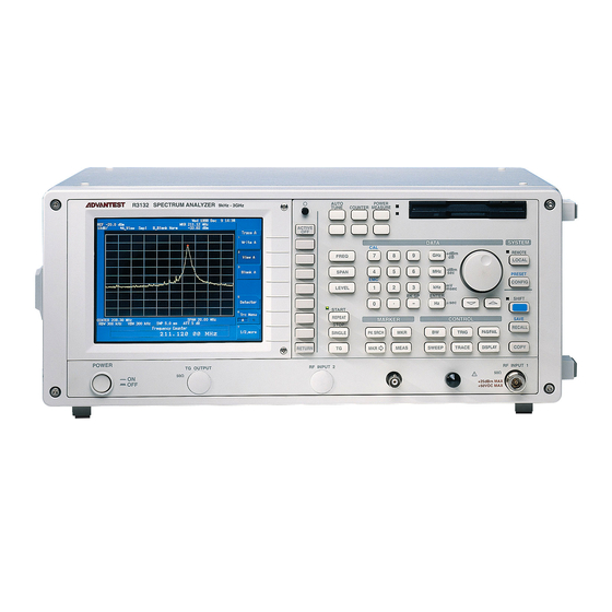
Describes the R3132 Series spectrum analyzer's synthesized local method and key features.
1.2 Accessories
Standard Accessories List
Lists standard accessories shipped with the spectrum analyzer.
1.4 Operating Environment
Environmental Conditions
Details ambient temperature, humidity, and area requirements for operation.
1.4 Operating Environment
Power Requirements
Lists power supply specifications including voltage range and frequency.
Power Fuse
Explains the location and procedure for checking or replacing the power fuse.
1.6 Cleaning, Storing and Transporting the R3132 Series Spectrum Analyzer
Cleaning
Provides instructions for removing dust and dirt from the spectrum analyzer.
1.6 Cleaning, Storing and Transporting the R3132 Series Spectrum Analyzer
Storing
Details storage conditions for the spectrum analyzer.
Transporting
Outlines guidelines for packing and shipping the spectrum analyzer.
2 OPERATION
Panel Description
Provides detailed views and explanations of the front panel keys and connectors.
2.2 Basic Operation
Operating Menus and Entering Data
Explains how to use panel keys and soft keys to operate the analyzer and enter data.
2.2.14 Entering User-definable Antenna Correction Data
Creating a correction data table
Describes the process of saving an empty correction data table to a floppy disk.
2.2.15 External Mixer (OPT16 thru OPT19)
Product Summary
Summarizes the product details for external mixers.
Configuration of the Options
Details the configuration of the external mixer options.
2.3 Measurement Examples
Measuring the Channel Power
Demonstrates how to measure channel power using the analyzer's function.
2.3.3 Measuring Adjacent Channel Leakage Power (ACP)
Full screen mode
Calculates channel leakage power and ratios using data on the entire screen.
Separate screen mode
Measures adjacent channel leakage powers on lower screens for higher accuracy.
2.3.10 FM Demodulation Function (OPT73)
FM Deviation Measurement
Explains how to measure FM deviation, sensitivity, and linearity.
Sensitivity Measurement
Details the calculation of ΔF/ΔT of trace data for sensitivity measurement.
Linearity Measurement
Describes measuring linearity error using trace and reference line differences.
2.4 Other Functions
Using Floppy Disks
Explains how to use the 3.5-inch floppy disk drive for saving and accessing data.
2.4 Other Functions
Removing Floppy Disks
Provides steps for removing floppy disks from the drive.
Initializing Floppy Disks
Guides on preparing a floppy disk for use by formatting it.
2.4.2 Saving or Recalling Data
Saving Data
Lists data types that can be saved to internal memory or floppy disk.
2.4.2 Saving or Recalling Data
Protecting Data
Explains how to use the file protection feature to prevent accidental overwriting.
2.4.2 Saving or Recalling Data
Loading Data
Describes how to access saved conditions and trace data.
2.4.2 Saving or Recalling Data
Deleting the Data
Explains how to delete saved data files.
2.4.3 Outputting Screen Data
Saving to a Floppy Disk
Explains how to save screen data in BMP format to a floppy disk.
2.4.3 Outputting Screen Data
Printing screen data
Describes how to send screen data to a Centronix compatible printer.
2.4.5 Setting the Screen Title
Setting titles
Describes how to enter alphanumeric and special characters for screen data remarks.
3 REFERENCE
Menu Index
Provides an index to find keys described in Chapter 3.
3.3 Menu Function Descriptions
AUTO TUNE Key (Auto Tuning)
Explains how AUTO TUNE automatically adjusts frequency span and reference level.
3.4 List of Settings
Factory Defaults
Lists the factory default settings for analyzer parameters and configurations.
3.4 List of Settings
Defaults Configuration Values
Lists the default settings applied when the Default Config softkey is pressed.
4 REMOTE PROGRAMING
GPIB Command Index
Provides an alphabetical index of GPIB commands for remote control.
4.2 GPIB Remote Programming
GPIB
Explains the GPIB interface, its bus configuration, and device functions.
4.2.2 GPIB Setup
Connecting the GPIB
Illustrates standard GPIB connector connection and stacking methods.
4.2.8 Status Byte
Status Register
Explains the hierarchical status register structure and its components: condition, event, and enable registers.
4.2.8 Status Byte
Status byte register
Describes the arrangement of status registers and their functions.
Standard event register
Details the bits and their meanings within the standard event register.
4.2.8 Status Byte
Standard operation status register
Shows bit assignments for the standard operation status.
Standard event register
Explains the meanings of bits in the standard event register.
4.2.8 Status Byte
Status Byte Register
Summarizes status information and explains its structure and service request response.
4.2.9 GPIB Command Codes
Table 4-1 Frequency (1 of 3)
Lists GPIB commands related to frequency settings and their formats.
4.2.9 GPIB Command Codes
Table 4-1 Frequency (2 of 3)
Continues the list of GPIB commands related to frequency settings.
4.2.9 GPIB Command Codes
Table 4-1 Frequency (3 of 3)
Concludes the list of GPIB commands related to frequency settings.
4.2.9 GPIB Command Codes
Table 4-2 Level
Lists GPIB commands for setting and querying levels.
Table 4-3 BW
Lists GPIB commands for setting Resolution Bandwidth (RBW) and Video Bandwidth (VBW).
4.2.9 GPIB Command Codes
Table 4-4 Sweep
Lists GPIB commands for controlling sweep time, mode, and gating.
4.2.9 GPIB Command Codes
Table 4-5 Trigger
Lists GPIB commands for setting trigger modes, slopes, and delays.
4.2.9 GPIB Command Codes
Table 4-6 Trace (1 of 2)
Lists GPIB commands for controlling trace modes and data display.
4.2.9 GPIB Command Codes
Table 4-6Trace (2 of 2)
Continues the list of GPIB commands for trace control and math functions.
4.2.9 GPIB Command Codes
Table 4-7 Pass/Fail
Lists GPIB commands for setting Pass/Fail judgments and limit line attributes.
4.2.9 GPIB Command Codes
Table 4-8 Display
Lists GPIB commands for controlling display settings like lines, windows, and zoom.
4.2.9 GPIB Command Codes
Table 4-9 MKR (1 of 2)
Lists GPIB commands for marker functions, including setting, moving, and searching peaks.
4.2.9 GPIB Command Codes
Table 4-9MKR (2 of 2)
Continues the list of GPIB commands for multi-marker setup and peak list functions.
4.2.9 GPIB Command Codes
Table 4-11 Meas (1 of 3)
Lists GPIB commands for measurement functions like noise, distortion, and modulation.
4.2.9 GPIB Command Codes
Table 4-11 Meas (2 of 3)
Continues the list of GPIB commands for phase noise and phase jitter measurements.
4.2.9 GPIB Command Codes
Table 4-11 Meas (3 of 3)
Concludes the list of GPIB commands for IM measurement, and Hi Sens.
4.2.9 GPIB Command Codes
Table 4-14Power (1 of 3)
Lists GPIB commands for power measurements like channel power and total power.
4.2.9 GPIB Command Codes
Table 4-14Power (2 of 3)
Lists GPIB commands for ACP and Spectrum Mask measurements.
4.2.9 GPIB Command Codes
Table 4-14Power (3 of 3)
Lists GPIB commands for spurious measurements and pass/fail judgments.
4.2.9 GPIB Command Codes
Table 4-15 EMC
Lists GPIB commands for EMC trace detection and antenna correction.
4.2.9 GPIB Command Codes
Table 4-16 CAL
Lists GPIB commands for calibration routines.
4.2.9 GPIB Command Codes
Table 4-17 Save Recall
Lists GPIB commands for saving and recalling data and settings.
4.2.9 GPIB Command Codes
Table 4-18 Config
Lists GPIB commands for configuring printer, bitmap output, and file settings.
Table 4-19 Preset
Lists GPIB commands for preset and reset functions.
4.2.9 GPIB Command Codes
Table 4-20 Test
Lists GPIB commands for self-test functions.
Table 4-21 GPIB
Lists GPIB commands for trace input/output and status byte operations.
4.2.9 GPIB Command Codes
Table 4-22 Others
Lists GPIB commands for display settings and FM demodulation.
Table 4-23 FM Demodulation (OPT73) (1 of 2)
Lists GPIB commands for FM demodulation, including range and sensitivity.
4.2.9 GPIB Command Codes
Table 4-23 FM Demodulation (OPT73) (2 of 2)
Continues FM demodulation commands, covering linearity and calibration.
4.2.9 GPIB Command Codes
Table 4-25 Entry
Lists GPIB commands for entering data, including numeric values and units.
4.2.10 Example Programs
Sample Programs for Setting or Reading Measurement Conditions
Provides sample Visual Basic programs for setting and reading measurement conditions.
4.2.10 Example Programs
Sample Programs for Reading Data
Explains how to output measurement data or settings using the "xx?" command.
4.2.10 Example Programs
Sample Programs for Inputting or Outputting Trace Data
Describes how to input or output trace data in ASCII or binary format.
4.2.10 Example Programs
Example VB-14: Read the trace data in ASCII format
Provides a Visual Basic example for reading trace data in ASCII format.
Example VB-15: Read the A memory data in binary format
Provides a Visual Basic example for reading memory data in binary format.
4.2.10 Example Programs
Example VB-16: Enter data into A memory in ASCII mode
Provides a Visual Basic example for entering data into memory in ASCII mode.
4.2.10 Example Programs
Example VB-17: An ACP measuremant is taken and then the measurement result is read (using the TS command)
Shows an example program for ACP measurement using the TS command.
4.2.10 Example Programs
Example VB-18: Execute single sweeping and wait until its finished (when not using SRQ)
Provides a VB example to check status byte for sweep completion without SRQ.
Example VB-19: Reading the peak frequency and level at the end of a single sweep (when using SRQ)
Provides a VB example for reading peak frequency and level using SRQ.
4.2.10 Example Programs
Example Program Used to Read Screen Data
Explains how to output the current screen data in bitmap format and save it.
4.3 RS-232 Remote Control Function
GPIB and RS-232 Compatibility
States that control codes and functions are the same as GPIB, except for GPIB-specific references.
Features of RS-232 Remote Control
Lists controllable functions via serial control.
Parameter Setup Window
Displays the parameter setup window for RS-232 communication.
4.3 RS-232 Remote Control Function
Interface connection
Shows the physical connection between the controller and the spectrum analyzer.
4.3 RS-232 Remote Control Function
Data Format
Explains that transmission messages are in ASCII code, followed by CR/LF.
4.3 RS-232 Remote Control Function
Differences Between RS-232 and GPIB
Highlights differences in command code and trace data handling between RS-232 and GPIB.
Panel Control
Describes how panel control is affected during remote operation.
4.3 RS-232 Remote Control Function
Remote Control Usage Examples
Provides typical remote control command examples in Microsoft Quick Basic.
5 PERFORMANCE VERIFICATION
General
Introduces performance verification procedures and lists items for TG and FM Demodulation.
Procedures of Performance Verification
Details performance verification procedures item by item.
Tracking Generator Performance Verification Procedure
Provides performance verification procedures for the tracking generator.
Performance Verification for OPT73 (FM Demodulation)
Provides performance verification procedures for the FM Demodulation option.
Performance Verification Record Sheet
Provides record sheets for measured values in each performance verification.
6 PERFORMANCE VERIFICATION (External Mixer)
External Mixer OPT16
Provides performance verification procedures for the External Mixer OPT16.
External Mixer OPT17
Provides performance verification procedures for the External Mixer OPT17.
External Mixer OPT18
Provides performance verification procedures for the External Mixer OPT18.
External Mixer OPT19
Provides performance verification procedures for the External Mixer OPT19.
7 SPECIFICATIONS
R3132 Specifications
Details the technical specifications for the R3132 spectrum analyzer.
R3132N Specifications
Details the technical specifications for the R3132N spectrum analyzer.
R3162 Specifications
Details the technical specifications for the R3162 spectrum analyzer.
R3172 Specifications
Details the technical specifications for the R3172 spectrum analyzer.
R3182 Specifications
Details the technical specifications for the R3182 spectrum analyzer.
Options
Lists and details the available options for the spectrum analyzer.
APPENDIX
ERROR MESSAGE
Lists error messages and their descriptions for troubleshooting.
Need help?
Do you have a question about the R3162 and is the answer not in the manual?
Questions and answers