Table of Contents
Advertisement
Quick Links
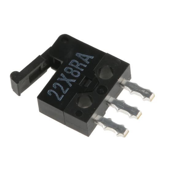
Ultra Subminiature Basic Switch
Snap-action Switch with Ultra
Subminiature Size (6.5 8.2
(H
W
D)) and Light Weight (0.3 g)
Excellent electrical characteristics and a snap-ac-
tion mechanism in spite of its ultra small size.
Gold-plated (Au-P) contacts for micro load
switching available in addition to silver-plated
contacts (Ag-P).
Ideal for applications where size is extremely
limited and high reliability is demanded, such as in
compact audio, optical. and telecommunications
equipment.
Ordering Information
Model Number Legend
D2MQ-1
- -
1
2
3
4
1.
Ratings
1:
Silver-plated contact type (0.5 A at 30 VDC)
Gold-plated contact type (50 mA at 30 VDC)
2.
Actuator
None: Pin plunger
L:
Leaf lever
D2MQ-4L-
-1-
1
2
3
1.
Actuator
4L: Hinge leaf lever
2.
Contact Material (Rating)
None: Silver-plated (0.5 A at 30 VDC)
105:
Gold-plated (50 mA at 30 VDC)
List of Models
Actuator
Terminals
Pin plunger
D2MQ-1
Leaf lever
D2MQ-1L
Hinge leaf lever
D2MQ-4L-1
Note:
The terminal shape drawings indicate the shape when the Switch is viewed from the direction of the arrow in the drawing below.
2.7 mm
Standard model (Ag-plated)
Straight
Left-angled
terminals
terminals
D2MQ-1-TL
D2MQ-1L-TL
D2MQ-4L-1-L
Authorised Distributors:-
ASH & ALAIN INDIA PVT LTD
S-100, F.I.E.E., Okhla Industrial Area, Phase-ii, New Delhi-110020(India)
Tel : 011-43797575 Fax : 011-43797574 E-mail : sales@ashalain.com
3.
Contact Material
None: Silver-plated
105:
Gold-plated
4.
Terminals
None: Straight terminals
TL:
Left-angled terminals
TR:
Right-angled terminals
3.
Terminals
None: Straight terminals
L:
Left-angled terminals
R:
Right-angled terminals
Right-angled
Straight
terminals
terminals
D2MQ-1-TR
D2MQ-1-105
D2MQ-1L-TR
D2MQ-1L-105
D2MQ-4L-1-R
D2MQ-4L-105-1
D2MQ
Micro load model (Au-plated)
Left-angled
terminals
---
---
---
---
D2MQ-4L-105-1-L
D2MQ-4L-105-1-R
Right-angled
terminals
Advertisement
Table of Contents

Subscribe to Our Youtube Channel
Related Manuals for Omron D2MQ Series


Summary of Contents for Omron D2MQ Series
- Page 1 Authorised Distributors:- ASH & ALAIN INDIA PVT LTD S-100, F.I.E.E., Okhla Industrial Area, Phase-ii, New Delhi-110020(India) Tel : 011-43797575 Fax : 011-43797574 E-mail : sales@ashalain.com Ultra Subminiature Basic Switch D2MQ Snap-action Switch with Ultra Subminiature Size (6.5 8.2 2.7 mm D)) and Light Weight (0.3 g) Excellent electrical characteristics and a snap-ac- tion mechanism in spite of its ultra small size.
- Page 2 Approx. 0.3 g Note: 1. The data given above are initial values. 2. The values are for the pin plunger models. (For different models, consult your OMRON representative.) 3. Malfunction: 1 ms max. 4. For testing conditions, consult your OMRON sales representative.
-
Page 3: Mounting Holes
D2MQ D2MQ Engineering Data (Reference Values) Mechanical Durability Electrical Durability (D2MQ-1) (D2MQ-1) 1,000 Ambient temperature: 20±2°C Ambient temperature: 20±2°C Ambient humidity: 65±5% Ambient humidity: 65±5% Operating frequency: 20 operations/min Without load Full stroke Operating frequency: 120 operations/min cosφ=1 Overtravel (mm) Switching current (A) Dimensions Note: All units are in millimeters unless otherwise indicated. - Page 4 D2MQ D2MQ Dimensions and Operating Characteristics Note: 1. All units are in millimeters unless otherwise indicated. 2. Unless otherwise specified, a tolerance of 0.15 mm applies to all dimensions. 3. The following illustrations are for the straight terminal models. Those for the left-angled terminals and right-angled terminals are different from straight terminal models in terminal size only.
-
Page 5: Operation
D2MQ D2MQ Precautions Refer to pages 26 to 31 for common precautions. Correct Use Cautions Mounting Terminal Connections Use M1.4 mounting screws with screws to securely mount the Switch. Tighten the screws to a torque of 0.1 N S m {1 kgf S cm}. Make sure that the capacity of the soldering iron is 15 W maximum (temperature of soldering iron: 250°C max.). - Page 6 General Information General Information Correct Use Electrical Conditions Area Item Page Load Using Switches The switching capacity of a switch significantly differs depending on Selecting Correct Switch whether the switch is used to break an alternating current or a direct Electrical Load current.
-
Page 7: General Information
General Information General Information Contact Protective Circuit Apply a contact protective circuit (surge killer) to extend contact du- When a switch is used under high humidity, arcs resulting from cer- rability, prevent noise, and suppress the generation of carbide or ni- tain types of load (e.g., inductive loads) will generate nitrious oxides tric acid due to arc. -
Page 8: Mechanical Conditions
General Information General Information Mechanical Conditions Switching Speed and Frequency The switching frequency and speed of a switch have a great influ- Operating Stroke Setting ence on the performance of the switch. Pay attention to the follow- The setting of stroke is very important for a switch to operate with ing. -
Page 9: Terminal Connections
General Information General Information • Incorrect Do not modify the actuator. If the actuator is modified, excessive external force may be applied to the internal switch mechanism, Snap-back characteristics may change, and the switch may stop Shock operation functioning. • If an external actuator is used as an operating object, check the material and thickness of the lever to make sure that the force applied to the lever is within the permissible range. - Page 10 General Information General Information terminals, otherwise the terminal may be deformed or the housing Operation and Storage Environment may be damaged. Handling Wiring Work Do not apply oil, grease, or other lubricants to the sliding parts of a When wiring a switch, check the insulation distance between the switch.
- Page 11 General Information General Information Switch Trouble and Corrective Action Type Location Failure Possible cause Corrective action of failure Failures Contact Contact Dust and dirt on the contacts. Remove the cause of the problem, place related to fi l failure the switch in a box, or use a sealed i h i Water or other liquid has penetrated into a electrical...
Need help?
Do you have a question about the D2MQ Series and is the answer not in the manual?
Questions and answers