
Related Manuals for Rosenbauer FOX


Summary of Contents for Rosenbauer FOX
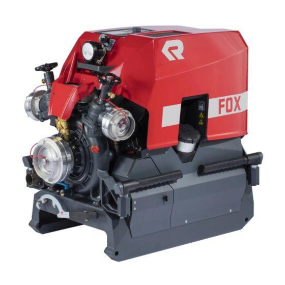
- Page 1 Operation manual FOX (4th generation) Portable fire pump Item number: 11033A-003 Release: 04/2017 (Rev.02) Language: English Abbreviation: JWin...
-
Page 2: Table Of Contents
Table of contents 1 Legal notice ......... 1.1 Copyright . - Page 3 7.2.1 Positioning the portable fire pump ... . . 7.3 Starting the engine ......7.3.1 Switch on ignition .
-
Page 4: Legal Notice
Copyright ORIGINAL OPERATION MANUAL Legal notice Copyright All rights to this manual and its attachments lie with Rosenbauer International AG. The documents are only entrusted to the recipient for their personal use. Reproduction, reprinting (electronically or mechanically), translations in other languages or all other duplication, also of parts of the manual, are only allowed with written permission. -
Page 5: Declaration Of Conformity
Address: Postbox 176, 4021 Linz, Austria Telephone: +43 (0)732 / 6794-0 that the portable fire pump for fire fighting operations Type FOX portable fire pump (4th generation) Serial number PC116 complies with the following regulations: 2006/42/EC - EC Machinery Directive... -
Page 6: Introduction
If this manual contains a technical error or a typographical error, Rosenbauer reserves the right to make change at any time and without no- tice. This manual may contains figures and descriptions, that are not built into the delivered product. -
Page 7: Identification
Introduction Identification Identification Identifying the serial number is important when referring to the manufactur- er in regards to spare parts and technical issues. The serial number of the portable fire pump is located on the operator side, facing away from the area of the engine frame, on the chassis type plate. ►... -
Page 8: Use Of The Operation Manual
Introduction Use of the operation manual Use of the operation manual 3.4.1 Validity This manual contains information needed for the operation of the product. This manual contains descriptions of special equipment as well as some abstractions and exemplary illustrations. The actual equipping of your prod- uct may therefore differ in part from the descriptions and illustrations. - Page 9 Introduction Use of the operation manual Warning notices The safety information warns the user of risk and informs them how these risks can be avoided. Safety information stands at the beginning of a chapter before handling in- structions from which a dangerous situation can occur. Further safety infor- mation is found at the start of this manual.
-
Page 10: Safety
Safety Intended use Safety Intended use The portable fire pump: • may only be used in fire fighting operations • may only be used with drinking water and fire fighting water (wastewa- ter- capable) • may only be operated under supervision •... -
Page 11: Training And Qualifications
Personnel must exhibit physical and mental aptitude. Minors and persons without qualified training may not operate the product. Modifications and conversions to the product may be performed only with written authorisation from Rosenbauer and must be performed by a manu- facturer-authorised person. 11 / 97... -
Page 12: General Safety Instructions
Observe the operation and maintenance manuals of additional products. If you cannot rectify faults yourself or repairs cannot be performed by spe- cially trained workshop personnel, Rosenbauer or the nearest Rosenbauer service partner must be contacted immediately. 12 / 97... -
Page 13: List Of Conventional Signs
Safety List of conventional signs List of conventional signs 4.6.1 Meaning of the warning signs Danger from electricity. Impending risk of explosion. Risk from oxidising materials. Risk of harmful or irritating materials. Impending risk of explosion. Impending acid burn risk. Impending hearing damage. - Page 14 Safety List of conventional signs Impending crushing risk. Danger from high pressure. Threat of environmental contamination. Impending shearing risk. Impending risk of tripping. Risk of hand injury. 14 / 97...
-
Page 15: Meaning Of The Prohibitory Signs
Safety List of conventional signs 4.6.2 Meaning of the prohibitory signs Handling fire and naked flames forbidden! Do not touch or reach in! Do not stay in the danger area! 15 / 97... -
Page 16: Meaning Of The Caution Signs
Safety List of conventional signs 4.6.3 Meaning of the caution signs Use hearing protection. Wear safety goggles or a safety mask. Wear a protective helmet. Wear protective gloves. Wear a protective suit. Maintain distance. Special caution. Observe environmental protection. 16 / 97... -
Page 17: Warning Notes
Safety Warning notes Warning notes DANGER! Danger of fatal injury or health hazard due to inhalation of toxic exhaust fumes! Combustion engines working in enclosed areas build toxic exhaust fumes. Is there the need of working in enclosed areas, obey following: Extract the exhaust fumes outside using exhaust hoses. - Page 18 Safety Warning notes WARNING! Danger of injury and accidents! Danger of injury and accidents due to malfunctioning or improper used safety devices! Do not override safety and protective devices. Do not manipulate or render safety and protective devices. Check safety and protective devices for proper function.
- Page 19 Safety Warning notes Explosion risk from flammable fuel! When working on fuel systems the fuel may ignite and cause life- threatening injuries.. Do no smoke. Keep fuel away from naked flame. If you are handling fuel keep a fire extinguisher to hand. ...
- Page 20 Safety Warning notes Serious injury to persons and damage due to water hammer effect! If water delivery via a pipe or hose is interrupted abruptly, a pressure impact known as the water hammer effect occurs; this is noticeable as a harsh noise (like a hammer hitting a pipe).
- Page 21 Safety Warning notes CAUTION! Danger of injury for the operator due to performing action in wrong order! Individual operating instructions must be done in the prescribed order. Danger of hearing damage due to extended presence in the vicinity of the running pump! Use hearing protection.
- Page 22 Safety Warning notes Injury to persons and material damage due to unexpected releasing of connecting couplings! Before start of operation (pressure), check all connecting couplings with a coupling wrench to ensure tight seating. Water under high pressure! Lingering in front of nozzle discharges could result in serious injuries. Do not linger in front of nozzle discharges.
- Page 23 Safety Warning notes Environmental and health hazard due to lubrication oils! Lubrication, transmission and hydraulic oils can cause permanent water pollution and endanger fauna and flora of all types. Avoid skin contact with hazardous oils. Avoid ground contact with lubrication oils. ...
- Page 24 Safety Warning notes NOTICE Damage due to cavitation! The pump capacity is reduced with increasing suction height. When operating with great suction heights, high pump speeds and very high discharge rates, the pump may cavitate. Cavitation causes extreme pressure and temperature peaks which can destroy the pump. Cavitation may sound like marbles are being pumped through the system.
-
Page 25: Product Description
The portable fire pump must be supplied from a tank, an open water source or a hydrant. An exact description of the supply takes place in chapter "Op- eration". Designation Assignment of the Rosenbauer designation for the standardized designa- tion. Rosenbauer identification Standardised designation EN1028... -
Page 26: Engine
Product description Engine Engine The propulsion engine of the portable fire pump is a 3-cylinder, 4-cycle gas- oline engine by Rotax, of type 903 ACE. The engine is a water-cooled alloy engine with 4 valves per cylinder. The cooling water and the lubricating oil is cooled via a closed cooling circuit by means of a water/water and a water/ air heat exchanging device with an electric fan. -
Page 27: Pump
Product description Pump Pump The single-stage centrifugal pump, consisting essentially of the impeller, main casing and bearing block, is made of a high corrosion resistance light alloy. The pump shaft is of stainless steel. The pump is provided with a cen- tral suction inlet with suction sieve, fixed coupling and blank cap. -
Page 28: Carrying Frame
Product description Carrying frame Carrying frame The motor-pump unit is fastened to the carrying frame by four elastic rub- ber-metal bearings. Four horizontal, fold-out, rubber-covered handles are integrated into the ends of the carrying frame. The handles can be locked in a longitudinal or perpendicular direction, depending on the carrying meth- od used. -
Page 29: Priming Pump Professional
Product description Priming pump Professional Priming pump Professional Because centrifugal pumps are not self suction pumps, the required vacu- um is created by an installed priming system. The priming pump is driven by a v-belt and only has to be engaged for the priming process. The priming pump is a manually or automatically controlled double-piston pump, which is made of corrosion-resistant light alloy. - Page 30 Product description Priming pump Professional Structure of the priming pump Priming pump Pressure valve plate Suction line Valve cover Suction valve plate Exhaust line Eccentric Main casing 30 / 97...
-
Page 31: Technical Description
Technical description Valves and actuators Technical description Valves and actuators X4 X107 X93 X108 Fuel tank cap X107 Beos charging socket (n.v.) Purge valve X108 RLS socket Spindle limit Battery box LCS 2.0 control panel Working light Handle Drain valve Screw-down valve Pressure outlet External drafting connection... - Page 32 Technical description Valves and actuators LCS 2.0 control panel S15a S16a S118 Display screen Acknowledge error message Back one screen page Forward one screen page Priming pump S15a Speed adjustment dial S16a Idle speed Ignition on / start the engine Ignition off / shut down the engine S118 Illumination (E11 - Working light, TB1 - Tank filling lighting, TB2 - Support frame...
- Page 33 Technical description Valves and actuators The lower left switch sends the portable fire pump into no-load condition (S16a). With the lower right switch, the lighting (S118) is turned on or off. 33 / 97...
-
Page 34: Display Unit Pilot Lamps
Technical description Display unit pilot lamps Display unit pilot lamps Screen page 1 - function displays Page indicator: The page indicator is only for orientation. It indicates the number of pages and highlights the requested page. Pump pressure control (optional): The control display illuminates green when the pump pressure control is ac- tivated, and the actual and target pressure lie within the tolerances. - Page 35 Technical description Display unit pilot lamps Pressure ramp: Visualizes the current discharge pressure as a ramp. With activated pump pressure control, the set pressure is displayed as a rising vertical line. Screen page 2 - status displays Fuel tank fluid level: The current fuel tank fluid level is represented by a percentage above the fuel gauge image.
- Page 36 Technical description Display unit pilot lamps Screen page 4 - Service indicators Operating hours: The hours of operation of the portable fire pump are shown next to the im- age display. Software version: The current software version is displayed next to the image display. Service interval hours: The operating hour-dependent service interval is shown next to the picture display.
- Page 37 Technical description Display unit pilot lamps Intake pressure monitoring system warning: If the intake pressure drops below 1.5 bar (incl. tolerance) with intake pres- sure monitoring system active the warning light is activated. The engine speed is then automatically reduced until the intake pressure has risen back to 1.5 bar.
-
Page 38: Governor
Technical description Governor Governor The pump pressure or speed are varied with the governor (S15a). Turn the dial clockwise to increase the pump pressure or engine speed. Turn the dial anti-clockwise to decrease the pump pressure or engine speed. -
Page 39: Optional Equipment
Technical description Optional equipment Optional equipment Exhaust gas hose DANGER! Inhalation of toxic exhaust fumes can cause death or serious damage to health! During operation of internal combustion engines in confined spaces, toxic gases build up. In order to properly discharge the hot exhaust gases, use the provided, standardized exhaust gas hose. - Page 40 Technical description Optional equipment Transport wheel set For manoeuvering and for one-man transport, the portable fire pump can be equipped with two transport wheels. Transport wheel set Scope of delivery: • 2 pcs. air-filled tyres • 2 pcs. axle for air-filled tyres •...
- Page 41 Technical description Optional equipment twice a year (depletion or replacement), because conditions for storage (vi- bration, high temperature fluctuations) reduce the knock resistance of the fuel. Fuel cannister Filler neck The filler neck, which is an attachment for the fuel cannister, must always be used when refuelling.
- Page 42 Technical description Optional equipment RLS1000 LED lighting system The RLS1000 light head can be attached by means of optional adapters on the carrying frame. This requires at least two extensions. To ensure operational safety, the RLS1000 can be turned on only when the engine is running and the battery voltage is greater than 11.5 V (see symbol - function indicators RLS illumination).
- Page 43 Technical description Optional equipment 5-key control panel Additional programmable special functions on the portable fire pump can be operated with the keys. • Competition mode • Training • Competition • Pressure preselection keys (only in conjunction with pump pressure governor option) •...
- Page 44 Technical description Optional equipment Please refer to a separate document for information on operating the other varieties. If the discharge pressure should be limited, either the speed is to be re- duced via governor, or the pump pressure governor is to be activated via the pressure preselection keys with a fixed discharge pressure.
-
Page 45: Operation
Operation Preparation for initial operation Operation Preparation for initial operation The sequence of the described processes is to be maintained without ex- ception! Before initial start-up, check the correct fluid level of all consumables. ► Oil in priming pump. For further information refer to Chapter "Priming pump" ... -
Page 46: Preparation For Start-Up
Operation Preparation for start-up Preparation for start-up WARNING! Potentially fatal injuries due to the engine taking in flammable gases! Do not operate the engine in areas with a heavy concentration of flammable vapors such as e. g. diesel, gas or propane. When handling flammable liquids and gases, always shut off the ... -
Page 47: Starting The Engine
Operation Starting the engine Starting the engine WARNING! Potentially fatal injuries due to the engine taking in flammable gases! Do not operate the engine in areas with a heavy concentration of flammable vapors such as e. g. diesel, gas or propane. When handling flammable liquids and gases, always shut off the ... -
Page 48: Switch On Ignition
Operation Starting the engine NOTICE Unplanned event The portable fire pump can be controlled at all times, even in critical operating states (e.g. burst hose). The approach depends on the situation and is the operator's responsibility. Variety1: ► Press S16 a Idlefunction switch. The speed of the portable fire pump is automatically reduced to ... - Page 49 Operation Starting the engine NOTICE Starting without control panel is switched on For a shortened start procedure, by a continuous actuation (approx. 5 sec.) of the Engine start function switch (S57) the portable fire pump can be put into operation. The portable fire pump is then operated with a predefined speed of 1700 min-1.
-
Page 50: Priming From An Open Water Source
Operation Priming from an open water source Priming from an open water source NOTICE Damage due to cavitation! The pump capacity is reduced with increasing suction height. When operating with great suction heights, high pump speeds and very high discharge rates, the pump may cavitate. Cavitation causes extreme pressure and temperature peaks which can destroy the pump. -
Page 51: Activate Drafting Operation From Open Water Source
Operation Priming from an open water source 7.4.1 Activate drafting operation from open water source ► Bring the portable fire pump into a good position in relation to the water source. Observe the inclination of the engine (max. 35° in the direction of ... -
Page 52: Hydrant Operation
Operation Hydrant operation Hydrant operation NOTICE Damage to the pump system due to use of contaminated water! Contaminated water can cause damage to the pump due to deposits. Before connecting the pressure hoses to the hydrant, open the hydrant and allow water to escape until only clean water flows. - Page 53 Operation Hydrant operation Pumping NOTICE Do not operate the pump in the cavitation area! Cavitating of the pump is perceptible as a noise (similar to pebbles being pumped). Never operate the portable fire pump without suction head or suction filter.
-
Page 54: Monitoring During Operation
Operation Monitoring during operation Monitoring during operation The LCS (Logic Control System) monitors: • engine starting/stopping, speed adjustment, • fuel capacity, cooling water temperature, oil pressure, etc. ► The speed of the engine can be changed using the governor (S15a). Optionally once this is reached, it is saved by pressing the governor (S15a). -
Page 55: Switching Off The Engine
Operation Switching off the engine Switching off the engine At high ambient temperatures (> 35°C) and an engine temperature of above 95°C allow the engine too cool down before switching it off in oper- ation. To do this operate the portable fire pump at approx. 2000-2500 min-1 in suction state (higher cooling performance) for approx. - Page 56 Operation Switching off the engine Disconnect the suction hoses before releasing the pressure from the riser pipes. The maximum pressure for suction hoses is 3 bar. After operating the pump with salt water or dirty water, the pump must be flushed with clean water! 56 / 97...
-
Page 57: Flush/Drain
Operation Flush/drain Flush/drain A thorough flushing with seawater or dirty water is to be carried out after each operation. If seawater or dirty water was sucked up with the priming pump, it is import- ant to rinse with clean water to prevent damage to the piston. After rinsing, the entire portable fire pump must be drained. -
Page 58: Transporting The Portable Fire Pump
Operation Transporting the portable fire pump Transporting the portable fire pump CAUTION! Risk of injury to operating personnel during transport Unfolded handles represent a tripping hazard! Fold the unfolded handles after use. If possible, always carry with 4 people and lift from the knees to reduce the risk of back injuries. -
Page 59: Transport By Means Of The Transport Wheels (Optional)
Operation Transporting the portable fire pump 7.9.2 Transport by means of the transport wheels (optional) For manoeuvering and for one-man transport, the portable fire pump can be equipped with two transport wheels. The carrying handles are swung in the direction of travel. The portable fire pump can then be lifted and moved by an operator. -
Page 60: 7.10 Tilting The Engine Cover
Operation Tilting the engine cover 7.10 Tilting the engine cover CAUTION! Danger of burning! Do not grip onto switched-on or recently switched-off search lights. There is a danger of crushing when closing the engine cover! Only touch the engine cover where appropriate (EC1). ... -
Page 61: 7.11 Fuelling And Refuelling
Operation Fuelling and refuelling: 7.11 Fuelling and refuelling: To perform a safe refuelling operation, it is essential to comply with all se- curity measures. WARNING! Risk of fire and explosion! When refuelling with a fuel canister, the filler neck must always be ... -
Page 62: Fuelling Operation When Engine Is Running
Operation Fuelling and refuelling: Limited shelf life of fuel The fuel in the tank of the portable fire pump must be utilised within six months. Otherwise deposits (sediments and precipitation) can occur. The fuel in the fuel canister is to be changed at least twice a year ... - Page 63 Operation Fuelling and refuelling: Refuelling: ► Prepare the fuel canister as shown (opened and with filler neck fitted correctly). ► Ensure that no ambience disturbances can arise. ► Ensure secure footing during refuelling (e.g. spillages - hot surfaces - engine). ►...
-
Page 64: Servicing And Cleaning
Only technology which is regularly maintained by specialists can meet the high demands. Rosenbauer service partners will gladly provide you with comprehensive advice about inspections and Service PLUS, as well as about the exact scope and costs of testing and maintenance work. - Page 65 Servicing and cleaning Engine component overview Type plate Camshaft sensor Thermostat housing Water pump housing Oil-water heat exchanger Oil filter housing Oil pressure regulator 65 / 97...
- Page 66 Servicing and cleaning Engine component overview Throttle valve joints Pressure and temperature sensor Airbox Engine speed sensor Control device Crankcase ventilation 66 / 97...
- Page 67 Servicing and cleaning Engine component overview Ignition coil E-Starter Fuel distributor Oil pressure switch 67 / 97...
-
Page 68: Service Plan
Servicing and cleaning Service plan Service plan 8.2.1 Oil change interval Symbol Work specification Priming pump ● ● ● Engine ● ● ● ● a. Whichever comes first b. Whichever comes first c. one-off fuel change after the first 10 operating hours 8.2.2 Inspection procedures Symbol... -
Page 69: Checking For Signs Of Leakage
Servicing and cleaning Service plan Symbol Work specification Check the coolant in the en- ● ● ● gine V-belt of the priming pump ● ● check air filter ● ● ● 8.2.3 Checking for signs of leakage Symbol Work specification Priming pump ●... -
Page 70: Lubrication Service
Servicing and cleaning Service plan 8.2.4 Lubrication service Symbol Work specification Carrying handles ● ● Shaft of pressure valves ● ● 70 / 97... -
Page 71: Lubrication Chart
Servicing and cleaning Lubrication chart Lubrication chart Description Medium Dosing Unit Engine oil SAE Engine oil Litres 15W40 Priming pump 0.65 (0.17) (gal- API/SF lons) MIL-L-46152 B Ford M2C-9011 GM 6048 M 5W40 engine oil - fully synthetic Engine 2 - 2.5 l Litres 4-stroke engine VOLVO VCS... -
Page 72: Inspection Procedures
Servicing and cleaning Inspection procedures Inspection procedures Testing and inspection procedures Assessment and inspection work may only be carried out by correspond- ingly trained fire-fighting personnel, who are familiar with the portable fire pump. The work must be carried out regularly, especially after each use, to ensure optimum operational safety of the portable fire pump. - Page 73 Servicing and cleaning Inspection procedures Priming pump All moving parts are oil-bath lubricated. Oil filler plug Oil drain plug Oil level sight glass Check oil level: ► Check the oil level of the priming pump with the sight glass. The oil level must be between the top and bottom markings. ...
- Page 74 Servicing and cleaning Inspection procedures Engine coolant inspection ► Remove the pressure cap from the compensation tank at room tem- perature. The coolant should be between the MIN and MAX markings in the compensation tank. ► If necessary, fill the tank with coolant and fit the pressure cap. Use VOLVO VCS coolant for the initial filling.
- Page 75 Servicing and cleaning Inspection procedures Change air filter The air filter of the portable fire pump engine should be replaced every 5 years. When using in regions with specially heavy dust loads the change, may take place earlier, depending on the contamination. ►...
- Page 76 Servicing and cleaning Inspection procedures Fuses and relays The electrical circuits on the electrical unit of the portable fire pump are se- cured with fuses. The fuse holder is located on the side away from the operator, behind the air filter box The fuse holder is located on the side opposite the operator, behind the air filter box Before replacing the burnt out fuse, check the cause of the defect.
- Page 77 Servicing and cleaning Inspection procedures Calibrate pressure sensors The pressure sensors built into the portable fire pump are absolute pres- sure sensors and are therefore subject to fluctuations in the atmosphere air pressure (high difference, weather conditions etc.). Before calibrating the pressure sensors ensure that the portable fire pump is in a depressurised state (drain valve J7 and screw-down valves J10 open, engine not started).
-
Page 78: Service Procedures
Servicing and cleaning Service procedures Service procedures Service work is work that may only be carried out by specially authorised expert personnel. This work is to be carried out or allowed to be carried out in accordance with the manufacturer's regulations. Maintain service intervals, as well as officially prescribed testing schedules and create written records for them. - Page 79 Servicing and cleaning Service procedures Top up oil ► Open oil filler plug ► Add oil using a suitable funnel and wait until it has run down. Oil quality and oil filling quantity, refer to chapter "Lubrication chart". ► Check that the oil level is between the MIN and MAX markings.
- Page 80 Servicing and cleaning Service procedures ► Completely screw on oil drain hose and drain oil. ► Collect the old oil and dispose of it properly. ► After approx. 1.7l used oil has flowed out, the 3 fastening screws (1) are opened on the oil filter housing (M11) and the oil filter (4) removed. Oil is drained.
- Page 81 Repeat process untilo 2.5 - 2.7 l of coolant is in the cooling circuit. If after three-times of repetition still the required 2.5 - 2.7 l is not in the cooling circuit, contact Rosenbauer customer service or the nearest Rosenbauer service centre.
- Page 82 Servicing and cleaning Service procedures Check valve plates of the priming pump Valve cover Valve plate To guarantee the full function of the priming pump, the valve plates must be checked for contamination and damage and replaced, if required, in the event of reduced performance.
- Page 83 Servicing and cleaning Service procedures Check valve plates after the installation ► Place steel ruler on the top of the valve cover. The ruler must be ap- plied on both sides of the cover. ► There must be a gap between the ruler and the mounting part, in the middle.
-
Page 84: General Guidelines For Handling Electronic Components
Servicing and cleaning Service procedures 8.6.1 General guidelines for handling electronic components NOTICE Neglecting these recommendations will result in loss of warranty. Working on vehicles fitted with electronic devices Installation and measurement of electronic devices. ► Ensure power is switched off before working on electrical parts (except when measuring). - Page 85 Servicing and cleaning Service procedures Painting work or working with chemicals or aggressive substances: NOTICE Damage to electronic components Due to high temperature in a paint box, electronics can be severely damaged. Expose electronics to max. 95 °C (203 °F) for a short period. ...
-
Page 86: Storage And Transport
Servicing and cleaning Service procedures 8.6.2 Storage and transport The portable fire pump and the corresponding installation material must be stored and transported in its packaging. It must be handled carefully and cautiously. Preserving and storing If the portable fire pump is not operated for a longer period of time (> 3 months) the following advice must be observed. -
Page 87: Troubleshooting
Troubleshooting Faults and their solutions - pump Troubleshooting Faults and their solutions - pump The following list offers an overview of possible faults on the pump. The list is not complete, but in the event of a malfunction it can be helpful in local- ising and rectifying the fault. -
Page 88: Faults And Their Solutions - Engine
Faults and their solutions - engine If problems or repairs can not be clearly identified or solved please contact the customer service department or your Rosenbauer representative. Faults and their solutions - engine The following list offers an overview of possible faults on the engine. The list is not complete, but in the event of a malfunction it can be helpful in lo- calising and rectifying the fault. - Page 89 Spark plug electrode gap too Measure electrode gap. If the electrode large gap is outside the tolerance, replace spark plugs. If problems or repairs can not be clearly identified or solved please contact the customer service department or your Rosenbauer representative. 89 / 97...
-
Page 90: Environmental Protection
Environmental protection Disposal of hazardous substances Environmental protection 10.1 Disposal of hazardous substances Dispose of all materials and old parts that are produced through the han- dling and repair of this unit in an environmentally sound way. Disposal of used oil, cooling water and fuels Used oil, cooling water and fuels are water-polluting substances. -
Page 91: Technical Data
Technical data Disposal of hazardous substances Technical data Pump Manufacturer Rosenbauer International AG Type PFPN 10-1000 PFPN 10-1500 DIN EN 14466 Number of stages Single-stage centrifugal pump Nominal discharge 1500 l/min Nominal supply pressure 10 bar Geodetic nominal suction height... - Page 92 Technical data Disposal of hazardous substances Engine Consumption approx. 14 l (at a constant 1500 l/ min at 10 bar (5200 min-1)) approx. 18 l (at a constant 1000 l/ at 15 bar (6000 min-1)) Engine control BOSCH ME17 Ignition system Electronic ignition system, ignition programme Spark plug...
-
Page 93: 11.1 Noise Measurements
Technical data Noise measurements Unit Dry weight approx. 150 kg (without fluids) Operating weight approx. 166 kg (full 20 l tank) Dimensions (L x W x H) approx. 923 x 636 x 845 Volume approx. 0.498 m³ Operating range -15 °C to +35 °C ambient tempera- ture (EN14466) 11.1 Noise measurements PFPN 10 - 1000... - Page 94 Technical data Noise measurements PFPN 10-1500 performance chart • Flow rate [l/min] • Total head discharge [bar] 94 / 97...
-
Page 95: List Of Spare Parts
12.1 List of spare parts Access to the online spare parts catalogue for the portable fire pump is pro- vided under the following link. https://spareparts.rosenbauer.com/template/index.php User name: PC11X Password: PC11X When logging in make sure you check for capitals and lower case. -
Page 96: List Of Abbreviations
List of abbreviations List of abbreviations Fire fighting specific abbreviations Power take off Normal pressure High pressure AFFF Aqueous film forming foam Piston priming pump, priming pump Aluminium technology O-stream nozzle Portable pump UHPS Ultra high pressure system Plastics and drinking water DVGW German Association of Gas &... - Page 97 List of abbreviations General abbreviations lbs/s Pounds per second Feet Gallons per minute 97 / 97...
Need help?
Do you have a question about the FOX and is the answer not in the manual?
Questions and answers