
Related Manuals for Harvia sentiotec MiniMy


Summary of Contents for Harvia sentiotec MiniMy
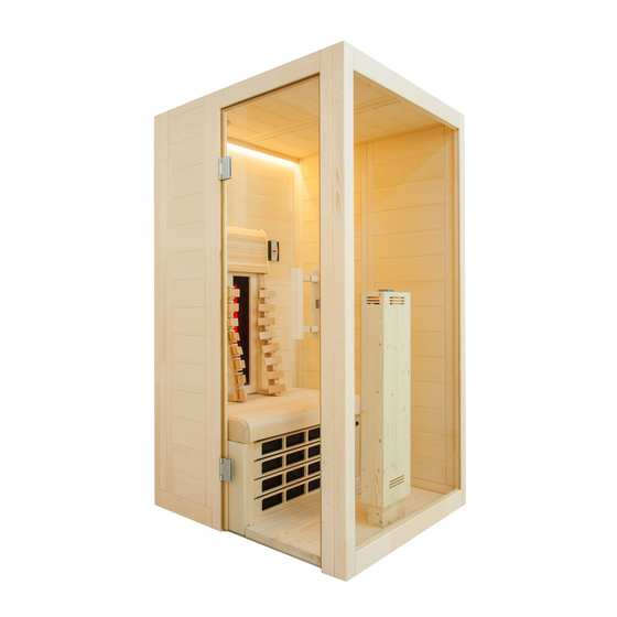
- Page 1 Infrarotkabine MiniMy 120 x 130 x 202 cm MONTAGE- UND GEBRAUCHSANWEISUNG Deutsch Version 06/19 Ident-Nr. 1-045-570...
-
Page 2: Table Of Contents
Inhaltsverzeichnis 1. Zu dieser Anleitung 2. Wichtige Hinweise zu Ihrer Sicherheit 2.1. Bestimmungsgemäßer Gebrauch 2.2. Sicherheitshinweise 3. Produktbeschreibung 3.1. Lieferumfang MiniMy 3.2. Produktfunktionen 4. Montage der Infrarotkabine MiniMy 4.1. Benötigtes Werkzeug 4.2. Stückliste Infrarotkabine MiniMy 4.3. Montage der Kabine 4.4. Montage der Inneneinrichtung 4.5. -
Page 3: Zu Dieser Anleitung
Montage- und Gebrauchsanweisung S. 3/38 1. Zu dieser Anleitung Lesen Sie diese Montage- und Gebrauchsanweisung gut durch und bewahren Sie sie in der Nähe der Infrarotkabine auf. So können Sie jederzeit Informationen zu Ihrer Sicherheit und zur Bedienung nachlesen. Sie finden diese Montage- und Gebrauchsanweisung auch im Download- bereich unserer Webseite auf www.sentiotec.com/downloads. -
Page 4: Wichtige Hinweise Zu Ihrer Sicherheit
Montage- und Gebrauchsanweisung S. 4/38 2. Wichtige Hinweise zu Ihrer Sicherheit Die Infrarotkabine ist nach anerkannten sicherheitstechnischen Regeln gebaut. Dennoch können bei der Verwendung Gefahren entstehen. Befolgen Sie deshalb die folgenden Sicherheitshinweise und die speziellen Warnhinweise in den einzelnen Kapiteln. 2.1. - Page 5 Montage- und Gebrauchsanweisung S. 5/38 ● Die Kabine darf nicht von Kindern unter 8 Jahren verwendet werden. ● Die Kabine darf von Kindern über 8 Jahren, von Personen mit verringerten psychischen, sensorischen oder mentalen Fähig- keiten und von Personen mit Mangel an Erfahrung und Wissen unter folgenden Bedingungen verwendet werden: –...
-
Page 6: Produktbeschreibung
Montage- und Gebrauchsanweisung S. 6/38 3. Produktbeschreibung 3.1. Lieferumfang MiniMy ● 1x 1-045-570 / Infrarotkabine MiniMy ● 1x 1-037-357 / Leistungsteil wave.com4 Infra ● 1x 1-012-222 / Bedienteil wave.com4 Infra ● 1x 1-009-265 / Netzanschlussleitung Infrarot 2,5m ● 1x 1-027-788 / Infrarotstrahler ECO 500 - dunkel (vormontiert)-Frontstrahler ●... -
Page 7: Produktfunktionen
Montage- und Gebrauchsanweisung S. 7/38 3.2. Produktfunktionen Infrarotkabine Massivkabine aus Fichtenholz für die Infrarotbestrahlung von 1 Person. Harzgallen sind kein Reklamationsgrund. Da in Fichtenholz immer wieder Harzgallen vorkommen und man beim Aussortieren nicht erkennen kann in welcher Tiefe diese sich befinden. Wenn diese knapp unter der Oberfläche sind brechen sie bei Hitzeent- wicklung auf und „bluten“... -
Page 8: Montage Der Infrarotkabine Minimy
Montage- und Gebrauchsanweisung S. 8/38 4. Montage der Infrarotkabine MiniMy Kontrollieren Sie, bevor Sie mit der Arbeit beginnen, anhand der Stückliste, ob alle Einzelteile auch tatsächlich mitgeliefert wurden. Sollten Einzelteile aus- nahmsweise fehlen, benachrichtigen Sie spätestens 14 Tage nach Erhalt der Kabine Ihren Händler. -
Page 9: Stückliste Infrarotkabine Minimy
Montage- und Gebrauchsanweisung S. 9/38 4.2. Stückliste Infrarotkabine MiniMy Bezeichnung Maß Bodenrahmen 1 Bodenrahmen hinten 103 x 9 x 4 cm 1 Bodenrahmen rechts 114 x 9 x 4 cm 1 Bodenrahmen links 42 x 9 x 4 cm Wandelemente 2 Wandelement A/A mit Multiclip 193 x 54 x 4 cm 1 Wandelement A/A mit Multiclip... - Page 10 Montage- und Gebrauchsanweisung S. 10/38 Bezeichnung Maß Inneneinrichtung 1 Strahlerkasten Fichte 105 x 23 x 12 cm 1 IR-Wärmeplatte inkl. Gitter 79,8 x 42 x 4,5 cm 1 Bank 94,5 x 56 x 10 cm 2 Ergo-Rückenlehne 70 x 18 x 10,5 cm 1 Kopfstütze VitaMy 35 x 27,5 x 8 cm 1 Rahmen für Strahler 350W Linde...
-
Page 11: Montage Der Kabine
Montage- und Gebrauchsanweisung S. 11/38 4.3. Montage der Kabine Die Kabine kann „Tür links“ oder „Tür rechts“ aufgebaut werden, beachten Sie dazu die Grundrisspläne auf Seite 36 und Seite 37. Montage des Bodenrahmens Abb. 1: Auflegen der drei Bodenrahmen-Elemente Grundriss „Tür links“ Grundriss „Tür rechts“... - Page 12 Montage- und Gebrauchsanweisung S. 12/38 Abb. 2: Bodenrahmen verbinden Schlagen Sie die Kunstoffschwalben vorsichtig mit einem Hammer, an den beiden Ecken des Bodenrahmens ein, bis diese bündig mit der Nut des Elements sind. Verwenden Sie einen Durchschlag oder ein Holzklötzchen, damit die Kunststoff- schwalbe gut versenkbar ist.
- Page 13 Montage- und Gebrauchsanweisung S. 13/38 Achtung! In weiterer Folge wird die Montage für Grundriss „Tür links“ beschrieben. Änderungen betreffend Montage für Grundriss „Tür rechts“ - siehe Seite 37. A bezeichnet immer die Sichtseite, dies ist auf der Oberseite der Wand- elemente gekennzeichnet.
- Page 14 Montage- und Gebrauchsanweisung S. 14/38 Abb. 4: Wandelemente mit Ecksteher verbinden Stecken Sie den Ecksteher von oben nach unten auf die Wandelemente. Ach- ten Sie dabei auf die korrekte Ausrichtung der „Multiclips“ (siehe Abb. 4). Der Ecksteher muss bündig mit den Wandelementen sein. Abb.
- Page 15 Montage- und Gebrauchsanweisung S. 15/38 Abb. 6: Wandelement mit Ausschnitt einsetzen Nachdem Sie das Strahlerelement eingesetzt haben, fahren Sie mit der zweiten Ecke fort. Abb. 7: Fertig montierte Wandelemente...
- Page 16 Montage- und Gebrauchsanweisung S. 16/38 Abb. 8: Verschrauben der Wandelemente Überprüfen Sie die rechten Winkel, bevor Sie die Wandelemente verschrauben. Beachten Sie den Tipp auf Seite 8. Bohrer 3 mm, 2 Stk. Schrauben 4 x 70 mm...
- Page 17 Montage- und Gebrauchsanweisung S. 17/38 Abb. 9: Montage des Glaselements Abb. 10: Montage des Türrahmen...
- Page 18 Montage- und Gebrauchsanweisung S. 18/38 Montage der Dachelemente Überprüfen Sie die rechten Winkel, bevor Sie die Wandelemente verschrauben. Beachten Sie den Tipp auf Seite 8. Abb. 11: Montage Dachauflageleisten Schrauben Sie die Dachauflageleisten wie in Abb. 11 an allen Wänden der Ka- bine fest.
- Page 19 Montage- und Gebrauchsanweisung S. 19/38 Abb. 13: Einlegen Dachelement hinten mit Lüfterausschnitt Abb. 14: Einlegen Dachelemente vorne Abb. 15: Befestigen der Dachelemente 12 Stk Schrauben: 3,5 x 35 mm...
- Page 20 Montage- und Gebrauchsanweisung S. 20/38 Abb. 16: Montage Abstandsleisten Rückwand Schrauben Sie die Abstandleisten an der Rückwand fest, wahlweise bündig oder bis zu 10 cm nach innen versetzt. Schrauben 4 Stk: 4 x 70...
- Page 21 Montage- und Gebrauchsanweisung S. 21/38 Montage der Entlüftung Abb. 17: Montage der Entlüftung Schrauben Sie das Basiselement der Entlüftung mit den 3 beiliegenden Schrau- ben fest. Schrauben Sie anschließend das Holzteller ein und sichern Sie die Schraube von außen mit der Kunststoffkappe.
-
Page 22: Montage Der Inneneinrichtung
Montage- und Gebrauchsanweisung S. 22/38 4.4. Montage der Inneneinrichtung Abb. 18: Bankauflagen montieren 4 Stk Schrauben: 4 x 70 mm 4 Stk Schrauben: 4 x 70 mm Abb. 19: Fußboden einlegen... -
Page 23: Montage Infrarot-Strahler Und Wärmeplatte
Montage- und Gebrauchsanweisung S. 23/38 4.5. Montage Infrarot-Strahler und Wärmeplatte Abb. 20: Frontstrahler fixieren Achten Sie darauf, dass die Kabel der Frontstrahler frei am Boden liegen und nicht durch den Kabinenboden eingeklemmt oder beschädigt werden. Nachdem der Strahler am Boden eingerastet ist, fixieren Sie diesen mit einer Drehung um 90°... - Page 24 Montage- und Gebrauchsanweisung S. 24/38 Abb. 22: Einlegen der Specksteinschale Abb. 21: Rückenstrahler (Infrarot-Strahler ECO 350) montieren VORSICHT! Achten Sie darauf, dass der Anschlusskasten der Strahler auf der Oberseite ist! Schrauben 4 Stk: 3 x 18 mm Setzten Sie den Strahler von innen in den Ausschnitt ein. Schrauben Sie den Strahler mit 4 Schrauben fest.
-
Page 25: Montage Der Led-Leiste
Montage- und Gebrauchsanweisung S. 25/38 Abb. 23: Einsetzen der IR-Wärmeplatte Achten Sie beim Einsetzen der IR-Wärmeplatte auf die Kabel der Schalter, diese dürfen nicht eingeklemmt oder beschädigt werden. Setzen Sie die IR-Wärmeplatte in die U-Leisten ein. Die Ausnehmung dient zur Durchführung der Leitung des Frontstrahles. - Page 26 Montage- und Gebrauchsanweisung S. 26/38 Anschluss des LED Stripes Abb. 25: Verbinden des LED Stripes mit der Steuerung Achten Sie beim Anschluss des LED Stripes auf den Pfeil am Stecker. Dieser muss beim Stripe an der Seite mit dem Aufdruck „+12V“ sein. Der Netzstecker der LED Beleuchtung muss sich außerhalb der Kabine befinden.
-
Page 27: Installation Der Infrarot-Steuerung
Montage- und Gebrauchsanweisung S. 27/38 4.7. Installation der Infrarot-Steuerung Beachten Sie für die Montage, Inbetriebnahme und Bedienung die An- leitung, welche der Steuerung beiliegt.Von der beiliegenden Steuerung wird lediglich die Betreibsart „Intensitätsregelung“ unterstützt. Anschluss des Leistungsteils Das Leistungsteil der Steuerung wird unter der Bank der Kabine platziert. Füh- ren Sie den Netzstecker durch die Öffnung in der Rückwand nach außen und schließen Sie die Leitungen wie folgt an. - Page 28 Montage- und Gebrauchsanweisung S. 28/38 Abb. 27: Anschlüsse Leistungsteil Stecker Beschreibung wave.com4 Infra Bedienteil IR-Heizgruppe 1 IR-Heizgruppe 2 Netzanschluss Lüfteranschluss (schwarz) - optional Lichtanschluss (grün)
-
Page 29: Montage Der Bank
Montage- und Gebrauchsanweisung S. 29/38 4.8. Montage der Bank Nachdem die Steuerung fertig angeschlossen ist, kann die Bank fertig montiert werden. Abb. 28: Fixieren der Sitzbank 2 Stk Schrauben: 4 x 70 mm Legen Sie die Bank auf die Auflageleisten. Schieben Sie die Sitzflächen nach vorne. -
Page 30: Montage Der Rückenlehnen Und Kopfstützen
Montage- und Gebrauchsanweisung S. 30/38 4.9. Montage der Rückenlehnen und Kopfstützen Die Montage des Rahmens für den Strahler erfolgt von der Rückseite (vorge- bohrt) mit 4 Stk. Schrauben 3,5 x 50 mm. Sollte dies nicht möglich sein, be- festigen Sie diesen mit den Schrauben von vorne (siehe Bild rechts). Schrauben Sie die Multiclips mit Hilfe der Montageschablone mit den 8 Stk. - Page 31 Montage- und Gebrauchsanweisung S. 31/38 Abb. 30: Montage Kopfstützen 4 Stk Schrauben: 3,5 x 35 mm Schrauben Sie die Halterungen seitlich bündig mit den Rückenlehnen fest. Die Höhe kann je nach Wunsch variiert werden. Stecken Sie anschließend die Kopf- stütze an die gewünschte Position.
-
Page 32: Montage Der Türe
Montage- und Gebrauchsanweisung S. 32/38 4.10. Montage der Türe Abb. 31: Montage Türbeschläge 1 Schrauben Sie die beiden Türbeschläge an der Glastür fest, achten sie dabei auf die gerade Ausrichtung der Beschläge und darauf, dass die Öffnung der Türe nach außen erfolgt. Die Ausrichtung der Beschläge wird durch die Justierung / Drehung der beiden Kunstoffringe vorgenommen. - Page 33 Montage- und Gebrauchsanweisung S. 33/38 Abb. 33: Montage Türgriff Setzen Sie zuerst die beiden Silikoneinlagen in die Bohrungen für den Türgriff am Glaselement ein. Danach verschrauben Sie die beiden Griffe vorsichtig miteinander. 2 Stk Schrauben: 5 x 100 mm Die untere Bohrung des Türgriffs ist in 92,5 cm Höhe. Die Türgriffe werden von innen miteinander verschraubt.
- Page 34 Montage- und Gebrauchsanweisung S. 34/38 Abb. 34: Montage Türmagnet Abb. 35: Montage Überschub-Blech...
-
Page 35: Reinigung Und Wartung
Montage- und Gebrauchsanweisung S. 35/38 5. Reinigung und Wartung 5.1. Reinigung ACHTUNG! Schäden an der Kabine ● Übergießen Sie die Kabine und die elektronischen Komponenten nicht mit Wasser. ● Reinigen Sie die Kabine und die elektronischen Komponenten nicht zu feucht. 5.2. -
Page 36: Technische Daten
Gebrauchsanweisung für den Anwender S. 36/38 8. Technische Daten Umgebungsbedingungen Lagertemperatur: - 25 °C bis + 70 °C Umgebungstemperatur: 20 °C bis + 30 °C Luftfeuchtigkeit: max. 95% 9. Grundriss Da Holz ein Naturprodukt ist, sind geringfügige Maßabweichungen möglich. 9.1. Grundriss „Tür links“... -
Page 37: Grundriss „Tür Rechts
Gebrauchsanweisung für den Anwender S. 37/38 9.2. Grundriss „Tür rechts“... -
Page 38: Änderungen Bei Montage Grundriss „Tür Rechts
Gebrauchsanweisung für den Anwender S. 38/38 9.3. Änderungen bei Montage Grundriss „Tür rechts“ Für die Montage des Glaselementes (Seite 17) Entfernen Sie die Multiclips beim Glaselement und montieren Sie diese mit Hilfe der beiliegenden Schablonen an gekennzeichneter Position. - Page 39 Infrared cabin MiniMy 120 x 130 x 202 cm INSTRUCTIONS FOR INSTALLATION AND USE English Version 06/19 ID no. 1-045-570...
- Page 40 Instructions for installation and use p. 2/38 1. About this instruction manual 2. Important information for your safety 2.1. Intended use 2.2. Safety information 3. Product description 3.1. MiniMy scope of delivery 3.2. Product features 4. Installation of the MiniMy infrared cabin 4.1.
-
Page 41: About This Instruction Manual
Instructions for installation and use p. 3/38 1. About this instruction manual Read these installation and operating instructions carefully and keep them within reach of the infrared cabin. This ensures that you can refer to information on safety and operation at any time. These installation and operating instructions can also be found in the downloads section of our website: www.sentiotec.com/downloads. -
Page 42: Important Information For Your Safety
Instructions for installation and use p. 4/38 2. Important information for your safety The infrared cabin has been produced in accordance with the appli- cable safety regulations for technical units. However, hazards may occur during use. Therefore adhere to the following safety infor- mation and the specific warning notices in the individual chapters. - Page 43 Instructions for installation and use p. 5/38 ● The cabin may not be used by children under 8 years old. ● The cabin may be used by children over 8 years old, by persons with limited psychological, sensory or mental capabilities or by persons with lack of experience/knowledge only under the fol- lowing conditions: –...
-
Page 44: Product Description
Instructions for installation and use p. 6/38 3. Product description 3.1. MiniMy scope of delivery ● 1x 1-045-570 / MiniMy infrared cabin ● 1x 1-037-357 / Power supply unit wave.com4 Infra ● 1x 1-012-222 / Operating unit wave.com4 Infra ● 1x 1-009-265 / Infrared mains connection cable, 2.5 m ●... -
Page 45: Product Features
Instructions for installation and use p. 7/38 3.2. Product features Infrared cabin Cabin made of solid spruce wood for the infrared radiation of one person. Pitch pockets are not grounds for return, since they can always appear in spruce wood and the depth at which they lie cannot be detected during the sorting-out process. -
Page 46: Installation Of The Minimy Infrared Cabin
Instructions for installation and use p. 8/38 4. Installation of the MiniMy infrared cabin Before you begin work, check the parts list to ensure that all the individual parts have been delivered. If you discover any missing parts, notify your dealer within 14 days of receiving the sauna cabin. -
Page 47: Parts List For Minimy Infrared Cabin
Instructions for installation and use p. 9/38 4.2. Parts list for MiniMy infrared cabin No. of Name Dimensions items Base frame 1 Base frame, rear 103 x 9 x 4 cm 1 Base frame, right 114 x 9 x 4 cm 1 Base frame, left 42 x 9 x 4 cm Wall elements... - Page 48 Instructions for installation and use p. 10/38 No. of Name Dimensions items Interior fittings 1 Spruce heater box 105 x 23 x 12 cm 1 IR heat panel incl. lattice 79.8 x 42 x 4.5 cm 1 Bench 94.5 x 56 x 10 cm 2 Ergonomic backrest 70 x 18 x 10.5 cm 1 VitaMy headrest...
-
Page 49: Cabin Installation
Instructions for installation and use p. 11/38 4.3. Cabin installation The cabin can have a “left-hand door” or “right-hand door” set-up; please note the corresponding floor plans on Page 36 and Page 37. Base frame installation Fig. 1: Laying the three base frame elements “Left-hand door”... - Page 50 Instructions for installation and use p. 12/38 Fig. 2: Connecting the base frame With a hammer, carefully drive in the plastic dovetail keys on both corners of the base frame until they are flush with the groove of the element. Use a punch or a wooden block so that the plastic dovetail key is adequately sunk.
- Page 51 Instructions for installation and use p. 13/38 Attention! The installation subsequently described is for the “left-hand door” floor plan. For changes affecting the installation for the “right-hand door” floor plan - see Page 37. A always refers to the visible side. This is labelled on the top side of the wall elements.
- Page 52 Instructions for installation and use p. 14/38 Fig. 4: Connecting wall elements with corner post Insert the corner post from above down onto the wall elements. When doing this, ensure that the Multiclips are correctly aligned (see Fig. 44). The corner post must be flush with the wall elements.
- Page 53 Instructions for installation and use p. 15/38 Fig. 6: Inserting wall element with recess After you have inserted the heater element, proceed with the second corner. Fig. 7: Pre-assembled wall elements...
- Page 54 Instructions for installation and use p. 16/38 Fig. 8: Screwing wall elements together Check the right angle before screwing the wall elements together. Observe the tip on Page 8. 3 mm drill bit, 2 screws 4 x 70 mm...
- Page 55 Instructions for installation and use p. 17/38 Fig. 9: Installing the glass element Fig. 10: Installing the door frame...
- Page 56 Instructions for installation and use p. 18/38 Installing the roof elements Check the right angle before screwing the wall elements together. Observe the tip on Page 8. Fig. 11: Installing the roof support slats Screw the roof support slats tight on all cabin walls as shown in Fig. 11. When doing this, ensure that the wall elements form a flush edge with the roof support slats.
- Page 57 Instructions for installation and use p. 19/38 Fig. 13: Inserting rear ceiling element with fan recess Fig. 14: Inserting front ceiling element Fig. 15: Fastening the ceiling elements 12 screws: 3.5 x 35 mm...
- Page 58 Instructions for installation and use p. 20/38 Fig. 16: Installing rear wall cover strips Screw the cover strips tight on the rear wall, either flush or offset up to 10 cm towards the inside. 4 screws: 4 x 70...
- Page 59 Instructions for installation and use p. 21/38 Installing the vent Fig. 17: Installing the vent Screw the basic vent element tight with the three supplied screws. Next, screw in the wood plate and secure the screw from the outside with the plastic cap.
-
Page 60: Installing The Interior Fittings
Instructions for installation and use p. 22/38 4.4. Installing the interior fittings Fig. 18: Installing the bench supports 4 screws: 4 x 70 mm 4 screws: 4 x 70 mm Fig. 19: Laying the floor... -
Page 61: Installing The Infrared Heater And Heat Panel
Instructions for installation and use p. 23/38 4.5. Installing the infrared heater and heat panel Fig. 20: Attaching the front heater Ensure that the front heater cables lie free on the floor and are not pinched by the cabin flooring or otherwise damaged. Once the heater is fitted into the recess on the floor, fasten it by turning the Allen screws clockwise 90°... - Page 62 Instructions for installation and use p. 24/38 Fig. 22: Inserting the soapstone bowl Fig. 21: Installing the back heater (ECO 350 infrared heater) CAUTION! Make sure that the connection box of the heater is on the top side! 4 screws: 3 x 18 mm Insert the heater from the inside into the recess.
-
Page 63: Installing The Led Strip
Instructions for installation and use p. 25/38 Fig. 23: Inserting the IR heat panel Pay attention to the switch cables when inserting the IR heat panel, and ensure that they are not pinched or damaged. Insert the IR heat panel into the U-rails. The recess provides the duct for the front heater cable. - Page 64 Instructions for installation and use p. 26/38 Connecting the LED strip Fig. 25: Connecting the LED strip to the control unit When connecting the LED strip, note the arrow on the connector. This must be on the side of the strip imprinted with “+12 V”. The mains plug of the LED lighting must be located outside the cabin.
-
Page 65: Installing The Infrared Control Unit
Instructions for installation and use p. 27/38 4.7. Installing the infrared control unit For installation, commissioning and operation, observe the manual which is included with the control unit. The supplied control unit only supports the “intensity regulation” operating mode. Connecting the power supply unit The power supply unit of the control unit is placed under the cabin bench. - Page 66 Instructions for installation and use p. 28/38 Fig. 27: Connections for power supply unit Plug Description wave.com4 infrared operating unit IR heating group 1 IR heating group 2 Mains connection Fan connection (black) - optional Light connection (green)
-
Page 67: Installing The Bench
Instructions for installation and use p. 29/38 4.8. Installing the bench Once the installation of the control unit is completed, the bench can be installed. Fig. 28: Attaching the bench 2 screws: 4 x 70 mm Lay the bench on the support slats. Push the seat surface forward. CAUTION! Secure the bench against sliding with the lock screws diagonally to the rear wall. -
Page 68: Installing The Backrests And Headrests
Instructions for installation and use p. 30/38 4.9. Installing the backrests and headrests The frame for the heater is assembled on the back side (pre-drilled) with four 3.5 x 50 mm screws. If this is not possible, fasten with the screws from the front (see image on right). - Page 69 Instructions for installation and use p. 31/38 Fig. 30: Installing headrests 4 screws: 3.5 x 35 mm Screw the brackets tight so they are laterally flush with the backrests. The height can be varied as required. Then insert the headrest into the preferred position.
-
Page 70: Installing The Doors
Instructions for installation and use p. 32/38 4.10. Installing the doors Fig. 31: Installing door fittings 1 Screw the two door fittings tight on the glass door while checking that the align- ment of the fittings are straight and that the doors are opened outward. The alignment of the fittings is achieved by adjusting/rotating the two plastic rings. - Page 71 Instructions for installation and use p. 33/38 Fig. 33: Installing door handle First, place the two silicone inserts in the drill holes for the door handle on the glass element. Afterwards, carefully screw the two handles together. 2 screws: 50 x 100 mm The bottom drill hole of the door handle is 92.5 cm high.
- Page 72 Instructions for installation and use p. 34/38 Fig. 34: Assembly of door magnet Fig. 35: Assembly of sleeve plate...
-
Page 73: Cleaning And Maintenance
Instructions for installation and use p. 35/38 5. Cleaning and maintenance 5.1. Cleaning ATTENTION! Damage to the cabin ● Never pour water on the cabin or the electrical components. ● Do not clean the cabin or the electrical components with too much moisture. 5.2. -
Page 74: Technical Data
Instructions for use for the user p. 36/38 8. Technical data Ambient conditions Storage temperature: - 25 °C to + 70 °C Ambient temperature: 20 °C to + 30 °C Relative humidity: max. 95% 9. Floor plan Since wood is a natural product, minor deviations in the dimensions can occur. 9.1. -
Page 75: Right-Hand Door" Floor Plan
Instructions for use for the user p. 37/38 9.2. “Right-hand door” floor plan... -
Page 76: Changes For Installation With "Right-Hand Door" Floor Plan
Instructions for use for the user p. 38/38 9.3. Changes for installation with “right-hand door” floor plan For the installation of the glass element (Page 17) Remove the Multiclips on the glass element and assemble them with the aid of the supplied template at the position indicated. - Page 77 Cabine infrarouge MiniMy 120 x 130 x 202 cm INSTRUCTIONS DE MONTAGE ET MODE D’EMPLOI Français Version 06/19 d’ident. 1-045-570...
- Page 78 Table des matières 1. Concernant ces instructions 2. Remarques importantes pour votre sécurité 2.1. Usage conforme 2.2. Consignes de sécurité 3. Description du produit 3.1. Étendue de la livraison MiniMy 3.2. Fonctions du produit 4. Montage de la cabine infrarouge MiniMy 4.1.
-
Page 79: Concernant Ces Instructions
Instructions de montage et mode d‘emploi p. 3/38 1. Concernant ces instructions Lisez attentivement ces instructions de montage et ce mode d’emploi et conser- vez-les à proximité de la cabine infrarouge. Vous pouvez ainsi consulter à tout moment des informations concernant son utilisation et relatives à votre sécurité. Ces instructions de montage et ce mode d’emploi sont également dis- ponibles dans la rubrique de téléchargement de notre site Internet www. -
Page 80: Remarques Importantes Pour Votre Sécurité
Instructions de montage et mode d‘emploi p. 4/38 2. Remarques importantes pour votre sécurité La cabine infrarouge est conçue selon des règles techniques de sécurité reconnues. Cependant, des dangers peuvent survenir lors de l’utilisation. C’est pourquoi vous devez suivre les consignes de sécurité... - Page 81 Instructions de montage et mode d‘emploi p. 5/38 ● La cabine ne doit pas être utilisée par des enfants de moins de 8 ans. ● La cabine peut être utilisée par des enfants de plus de 8 ans, par des personnes ayant des capacités psychiques, sensorielles ou mentales limitées et par des personnes manquant d’expérience et de connaissances que –...
-
Page 82: Description Du Produit
Instructions de montage et mode d‘emploi p. 6/38 3. Description du produit 3.1. Étendue de la livraison MiniMy ● 1x 1-045-570 / Cabine infrarouge MiniMy ● 1x 1-037-357 / Module de puissance wave.com4 Infra ● 1x 1-012-222 / Module de commande wave.com4 Infra ●... -
Page 83: Fonctions Du Produit
Instructions de montage et mode d‘emploi p. 7/38 3.2. Fonctions du produit Cabine infrarouge Cabine solide en bois d’épicéa pour l’exposition aux rayons infrarouges d’1 personne. Les poches de résine ne constituent pas un motif de réclamation. en raison de leur présence régulière dans le bois d’épicéa et de l’impossibilité de déterminer leur profondeur lors de la sélection du bois. -
Page 84: Montage De La Cabine Infrarouge Minimy
Instructions de montage et mode d‘emploi p. 8/38 4. Montage de la cabine infrarouge MiniMy Avant de commencer les travaux, vérifiez au moyen de la nomenclature si toutes les pièces ont bien été livrées. S’il devait s’avérer que des pièces manquent, informez votre revendeur dans les 14 jours suivant la réception de la cabine. -
Page 85: Liste Des Pièces Cabine Infrarouge Minimy
Instructions de montage et mode d‘emploi p. 9/38 4.2. Liste des pièces cabine infrarouge MiniMy Désignation Dimensions Cadre de plancher 1 Cadre de plancher arrière 103 x 9 x 4 cm 1 Cadre de plancher à droite 114 x 9 x 4 cm 1 Cadre de plancher à... - Page 86 Instructions de montage et mode d‘emploi p. 10/38 Désignation Dimensions Équipement intérieur 1 Boîtier radiateur pin 105 x 23 x 12 cm 1 Plaque chauffante IR avec grille 79,8 x 42 x 4,5 cm 1 Banc 94,5 x 56 x 10 cm 2 Dossier Ergo 70 x 18 x 10,5 cm 1 Appui-tête VitaMy...
-
Page 87: Montage De La Cabine
Instructions de montage et mode d‘emploi p. 11/38 4.3. Montage de la cabine La cabine peut être montée « Porte à gauche » ou « Porte à droite ». Référez-vous aux plans Page 36 et Page 37. Montage du cadre de plancher Fig. - Page 88 Instructions de montage et mode d‘emploi p. 12/38 Fig. 2 : Raccorder le cadre de plancher Tapez doucement sur les barrettes en plastique avec un marteau aux deux coins du cadre de plancher jusqu’à ce qu’elles affleurent la rainure de l’élément. Utilisez un poinçon ou un bloc de bois pour que la barrette en plastique puisse bien s’enfoncer.
- Page 89 Instructions de montage et mode d‘emploi p. 13/38 Attention ! Le montage du plan « Porte à gauche » est décrit ci-après. Pour les modifications concernant le montage du plan « Porte à droite », voir Page 37. A désigne toujours le côté apparent qui est indiqué sur la face supérieure des éléments muraux.
- Page 90 Instructions de montage et mode d‘emploi p. 14/38 Fig. 4 : Raccorder les éléments muraux avec les montants d’angle Placez le montant d’angle du haut vers le bas sur les éléments muraux. Assu- rez-vous que l’orientation des « multiclips » est correcte (voir Fig. 44). Le montant d’angle doit être à...
- Page 91 Instructions de montage et mode d‘emploi p. 15/38 Fig. 6 : Insérer l’élément mural avec la découpe Après avoir inséré l’élément de radiateur, continuez avec le deuxième coin. Fig. 7 : Éléments muraux montés...
- Page 92 Instructions de montage et mode d‘emploi p. 16/38 Fig. 8 : Vissage des éléments muraux Contrôlez les angles droits avant de visser les éléments muraux. Tenez compte du conseil à la Page 8. Foret de 3 mm, 2 vis 4 x 70 mm...
- Page 93 Instructions de montage et mode d‘emploi p. 17/38 Fig. 9 : Montage de l’élément en verre Fig. 10 : Montage du cadre de porte...
- Page 94 Instructions de montage et mode d‘emploi p. 18/38 Montage des éléments de toit Contrôlez les angles droits avant de visser les éléments muraux. Tenez compte du conseil à la Page 8. Fig. 11 : Montage baguettes d’appui de toit Vissez les baguettes d’appui de toit comme indiqué dans Fig. 11 sur tous les murs de la cabine.
- Page 95 Instructions de montage et mode d‘emploi p. 19/38 Fig. 13 : Insertion de l’élément de toit arrière avec la découpe du ventilateur Fig. 14 : Insertion de l’élément de toit avant Fig. 15 : Fixation des éléments de toit 12 vis : 3,5 x 35 mm...
- Page 96 Instructions de montage et mode d‘emploi p. 20/38 Fig. 16 : Montage barre d’écartement paroi arrière Vissez les barres d’écartement sur la paroi arrière, soit par montage affleurant, soit décalé jusqu’à 10 cm vers l’intérieur. 4 vis : 4 x 70...
- Page 97 Instructions de montage et mode d‘emploi p. 21/38 Montage de la ventilation Fig. 17 : Montage de la ventilation Vissez l’élément de base de la ventilation avec les 3 vis fournies. Vissez ensuite la plaque en bois et fixez la vis de l’extérieur avec le capuchon en plastique.
-
Page 98: Montage De L'équipement Intérieur
Instructions de montage et mode d‘emploi p. 22/38 4.4. Montage de l’équipement intérieur Fig. 18 : Monter les supports du banc 4 vis : 4 x 70 mm 4 vis : 4 x 70 mm Fig. 19 : Poser le plancher... -
Page 99: Montage Des Radiateurs Infrarouge Et De La Plaque Chauffante
Instructions de montage et mode d‘emploi p. 23/38 4.5. Montage des radiateurs infrarouge et de la plaque chauffante Fig. 20 : Fixer le radiateur avant Assurez-vous que les câbles des radiateurs avant sont librement posés au sol et ne sont pas pincés ou endommagés par le plancher de la cabine. Une fois que le radiateur est enclenché... - Page 100 Instructions de montage et mode d‘emploi p. 24/38 Fig. 22 : Insertion de la coupelle en pierre ollaire Fig. 21 : Monter le radiateur arrière (radiateur infrarouge ECO 350) PRUDENCE ! Veillez à ce que le boîtier de raccordement du radiateur soit sur la partie supérieure ! 4 vis : 3 x 18 mm Placez le radiateur par l’arrière dans la découpe.
-
Page 101: Montage De La Barre À Led
Instructions de montage et mode d‘emploi p. 25/38 Fig. 23 : Insertion de la plaque chauffante IR Lors de l’insertion de la plaque chauffante IR, faites attention aux câbles des interrupteurs. Ceux-ci ne doivent pas être pincés ou endommagés. Placez la plaque chauffante IR dans les barres en U. Le renfoncement sert à faire passer le câble du radiateur avant. - Page 102 Instructions de montage et mode d‘emploi p. 26/38 Raccordement de la bande LED Fig. 25 : Raccordement de la bande LED à la commande Lors du raccordement de la bande LED, faites attention à la flèche sur la prise. Celle-ci doit être sur le côté de la bande avec l’inscription « +12 V ». La fiche secteur de l’éclairage LED doit être située à...
-
Page 103: Montage De La Commande Infrarouge
Instructions de montage et mode d‘emploi p. 27/38 4.7. Montage de la commande infrarouge Pour le montage, la mise en service et l’exploitation, observez les ins- tructions fournies avec la commande. Cette commande prend en charge uniquement le mode « Régulation d’intensité ». Raccordement du bloc de puissance Le bloc de puissance de la commande est placé... - Page 104 Instructions de montage et mode d‘emploi p. 28/38 Fig. 27 : Raccordements du bloc de puissance Connecteur Description Élément de commande wave.com4 infra Groupe chauffant IR 1 Groupe chauffant IR 2 Raccordement au secteur Raccordement du ventilateur (noir) - facultatif Raccordement lumière (vert)
-
Page 105: Montage Du Banc
Instructions de montage et mode d‘emploi p. 29/38 4.8. Montage du banc Une fois la commande entièrement connectée, le banc peut être assemblé. Fig. 28 : Fixation du banc 2 vis : 4 x 70 mm Placez le banc sur les barres de support. Poussez les sièges vers l’avant. PRUDENCE ! Fixez le banc avec les vis de fixation en biais contre la paroi arrière afin d’éviter qu’il ne glisse. -
Page 106: Montage Des Dossiers Et Des Appui-Têtes
Instructions de montage et mode d‘emploi p. 30/38 4.9. Montage des dossiers et des appui-têtes Le montage du cadre pour le projecteur se fait par l’arrière (pré-perçage) avec 4 vis de 3,5 x 50 mm. Si ce n’est pas possible, fixez-le avec les vis par l’avant (voir photo de droite). - Page 107 Instructions de montage et mode d‘emploi p. 31/38 Fig. 30 : Montage des appui-têtes 4 vis : 3,5 x 35 mm Vissez les supports latéralement afin qu’ils affleurent les dossiers. La hauteur peut varier au choix. Ensuite, insérez l’appui-tête dans la position désirée.
-
Page 108: Montage Des Portes
Instructions de montage et mode d‘emploi p. 32/38 4.10. Montage des portes Fig. 31 : Montage des ferrures de portes 1 Vissez les deux ferrures de porte à la porte en verre, en vous assurant que les ferrures sont au niveau de la porte et que la porte s’ouvre vers l’extérieur. L’orientation des ferrures est effectuée en ajustant/tournant les deux bagues en plastique. - Page 109 Instructions de montage et mode d‘emploi p. 33/38 Fig. 33 : Montage de la poignée de porte Insérez d’abord les deux inserts en silicone dans les trous de la poignée de porte sur l’élément en verre. Ensuite, vissez soigneusement les deux poignées ensemble.
- Page 110 Instructions de montage et mode d‘emploi p. 34/38 Fig. 34 : Montage de l’aimant de la porte Fig. 35 : Montage de la tôle extérieure...
-
Page 111: Nettoyage Et Entretien
Instructions de montage et mode d‘emploi p. 35/38 5. Nettoyage et entretien 5.1. Nettoyage ATTENTION ! Dommages sur la cabine ● Ne versez pas d’eau sur la cabine et les composants électroniques. ● Ne nettoyez pas la cabine et les composants électroniques en utilisant trop d’humidité. -
Page 112: Caractéristiques Techniques
Mode d’emploi pour l’utilisateur p. 36/38 8. Caractéristiques techniques Conditions ambiantes Température de stockage : -25 °C à +70 °C Température ambiante : 20 °C à +30 °C Humidité de l’air : max. 95 % 9. Plan Comme le bois est un produit naturel, des écarts mineurs sont possibles. 9.1. -
Page 113: Plan " Porte À Droite
Mode d‘emploi pour l’utilisateur p. 37/38 9.2. Plan « Porte à droite »... -
Page 114: Modifications Lors Du Montage Selon Le Plan " Porte À Droite
Mode d’emploi pour l’utilisateur p. 38/38 9.3. Modifications lors du montage selon le plan « Porte à droite » Pour le montage de l’élément en verre (Page 17) Retirez les multiclips de l’élément en verre et montez-les dans la position mar- quée en utilisant les gabarits inclus. - Page 115 Infraroodcabine MiniMy 120 x 130 x 202 cm MONTAGE- EN GEBRUIKSAANWIJZING Nederlands Versie 06/19 Identificatienr. 1-045-570...
- Page 116 Inhoudsopgave 1. Over deze handleiding 2. Belangrijke aanwijzingen voor uw veiligheid 2.1. Gebruik volgens de voorschriften 2.2. Veiligheidsaanwijzingen 3. Productbeschrijving 3.1. Omvang van de levering MiniMy 3.2. Productfuncties 4. Montage van de infraroodcabine MiniMy 4.1. Vereist gereedschap 4.2. Stuklijst infraroodcabine MiniMy 4.3.
-
Page 117: Over Deze Handleiding
Montage- en gebruiksaanwijzing Pag. 3/38 1. Over deze handleiding Lees deze montage- en gebruiksaanwijzing goed door en bewaar deze in de buurt van de infraroodcabine. Zo kunt u te allen tijde informatie over uw veiligheid en de bediening nalezen. U vindt deze montage- en gebruiksaanwijzing ook in het downloadbereik van onze website www.sentiotec.com/downloads. -
Page 118: Belangrijke Aanwijzingen Voor Uw Veiligheid
Montage- en gebruiksaanwijzing Pag. 4/38 2. Belangrijke aanwijzingen voor uw veiligheid De infraroodcabine is gebouwd conform de erkende veiligheidstech- nische voorschriften. Toch kunnen bij het gebruik gevaren ontstaan. Neem daarom de volgende veiligheidsaanwijzingen en de speciale waarschuwingsaanwijzingen in de afzonderlijke hoofdstukken in acht. 2.1. - Page 119 Montage- en gebruiksaanwijzing Pag. 5/38 ● De cabine mag niet door kinderen onder 8 jaar worden gebruikt. ● De cabine mag door kinderen vanaf 8 jaar, door personen met gereduceerde fysische, sensorische of mentale vaardigheden en door personen met gebrekkige ervaring en kennis onder volgende omstandigheden worden gebruikt: –...
-
Page 120: Productbeschrijving
Montage- en gebruiksaanwijzing Pag. 6/38 3. Productbeschrijving 3.1. Omvang van de levering MiniMy ● 1x 1-045-570 / Infraroodcabine MiniMy ● 1x 1-037-357 / Voedingseenheid wave.com4 Infra ● 1x 1-012-222 / Bedieningspaneel wave.com4 Infra ● 1x 1-009-265 / Netaansluitleiding infrarood 2,5 m ●... -
Page 121: Productfuncties
Montage- en gebruiksaanwijzing Pag. 7/38 3.2. Productfuncties Infraroodcabine Massieve cabine van sparrenhout voor de infraroodbestraling van 1 persoon. Harsbuilen gelden niet als reclamatiereden. Omdat in sparrenhout van nature harsbuilen kunnen voorkomen en bij het sorteren niet kan worden herkend in welke diepte ze zich bevinden. Als ze zich net onder het oppervlak bevinden, kunnen ze bij hitte open- breken en gaan „bloeden”. -
Page 122: Montage Van De Infraroodcabine Minimy
Montage- en gebruiksaanwijzing Pag. 8/38 4. Montage van de infraroodcabine MiniMy Controleer alvorens met de montage te beginnen aan de hand van de stuklijst of alle afzonderlijke delen werden geleverd. Als er delen ontbreken, neem dan uiterlijk 14 dagen na ontvangst van de cabine contact op met uw handelaar. Voor de montage heeft u een tweede persoon nodig! Bovendien raden we aan om de gaten voor de schroeven voor te boren. -
Page 123: Stuklijst Infraroodcabine Minimy
Montage- en gebruiksaanwijzing Pag. 9/38 4.2. Stuklijst infraroodcabine MiniMy Aantal Benaming Maat Bodemframe 1 Bodemframe achter 103 x 9 x 4 cm 1 Bodemframe rechts 114 x 9 x 4 cm 1 Bodemframe links 42 x 9 x 4 cm Wandelementen 2 Wandelement A/A met multiclip 193 x 54 x 4 cm... - Page 124 Montage- en gebruiksaanwijzing Pag. 10/38 Aantal Benaming Maat Binneninrichting 1 Stralerkast sparrenhout 105 x 23 x 12 cm 1 IR-warmteplaat incl. rooster 79,8 x 42 x 4,5 cm 1 Bank 94,5 x 56 x 10 cm 2 Ergo-rugleuning 70 x 18 x 10,5 cm 1 Hoofdsteun VitaMy 35 x 27,5 x 8 cm 1 Frame voor straler 350 W lindehout...
-
Page 125: Montage Van De Cabine
Montage- en gebruiksaanwijzing Pag. 11/38 4.3. Montage van de cabine De cabine kan „deur links” of „deur rechts” worden opgebouwd. Neem hiervoor de plattegronden op pagina 36 en pagina 37 in acht. Montage van het bodemframe Afb. 1: Plaatsen van de drie bodemframe-elementen Plattegrond „Deur links”... - Page 126 Montage- en gebruiksaanwijzing Pag. 12/38 Afb. 2: Bodemframe verbinden Sla de kunststofverbindingen er voorzichtig met een hamer aan beide hoeken van het bodemframe in tot deze vlak afsluiten met de groef van het element. Gebruik een doorslag of een houten blokje om de kunststofverbinding er goed verzonken in te slaan.
- Page 127 Montage- en gebruiksaanwijzing Pag. 13/38 Attentie! Hieronder wordt de montage voor plattegrond „Deur links” beschreven. Wijzigingen met betrekking tot de montage voor plattegrond „Deur rechts” - zie pagina 37. A duidt altijd op de zichtzijde, dit is op de bovenzijde van de wandele- menten gekenmerkt.
- Page 128 Montage- en gebruiksaanwijzing Pag. 14/38 Afb. 4: Wandelementen met hoekstaanders verbinden Steek de hoekstaanders van boven naar beneden op de wandelementen. Let hierbij op de correcte uitlijning van de „multiclips” (zie Afb. 44). De hoekstaander moet vlak afsluiten met de wandelementen. Afb.
- Page 129 Montage- en gebruiksaanwijzing Pag. 15/38 Afb. 6: Wandelement met uitsparing plaatsen Nadat u het stralerelement heeft geplaatst, gaat u verder met de tweede hoek. Afb. 7: Klaar gemonteerde wandelementen...
- Page 130 Montage- en gebruiksaanwijzing Pag. 16/38 Afb. 8: Vastschroeven van de wandelementen Controleer de rechte hoek alvorens de wandelementen vast te schroeven. Let op de tip op pagina 8. Boormachine 3 mm, 2 stuks schroeven 4 x 70 mm...
- Page 131 Montage- en gebruiksaanwijzing Pag. 17/38 Afb. 9: Montage van het glaselement Afb. 10: Montage van het deurframe...
- Page 132 Montage- en gebruiksaanwijzing Pag. 18/38 Montage van de dakelementen Controleer de rechte hoek alvorens de wandelementen vast te schroeven. Let op de tip op pagina 8. Afb. 11: Montage daksteunlijsten Schroef de daksteunlijsten zoals in Afb. 11 aan alle wanden van de cabine vast. Zorg hierbij voor een vlakke afsluiting van wandelementen en daksteunlijst in een lijn.
- Page 133 Montage- en gebruiksaanwijzing Pag. 19/38 Afb. 13: Plaatsen van dakelement achter met ventilatoruitsparing Afb. 14: Plaatsen van dakelementen voorzijde Afb. 15: Bevestigen van de dakelementen 12 stuks schroeven: 3,5 x 35 mm...
- Page 134 Montage- en gebruiksaanwijzing Pag. 20/38 Afb. 16: Montage afstandslijsten achterwand Schroef de afstandslijsten aan de achterwand vast, naar keuze vlak afsluitend of tot 10 cm naar binnen verschoven. Schroeven 4 stuks: 4 x 70...
- Page 135 Montage- en gebruiksaanwijzing Pag. 21/38 Montage van de ontluchting Afb. 17: Montage van de ontluchting Schroef het basiselement van de ontluchting met de 3 bijgeleverde schroeven vast. Schroef vervolgens het houten bord erin en borg de schroef van buiten met de kunststof kap.
-
Page 136: Montage Van De Binneninrichting
Montage- en gebruiksaanwijzing Pag. 22/38 4.4. Montage van de binneninrichting Afb. 18: Banksteunen monteren 4 stuks schroeven: 4 x 70 mm 4 stuks schroeven: 4 x 70 mm Afb. 19: Vloer plaatsen... -
Page 137: Montage Infraroodstraler En Warmteplaat
Montage- en gebruiksaanwijzing Pag. 23/38 4.5. Montage infraroodstraler en warmteplaat Afb. 20: Frontstraler fixeren Zorg ervoor dat de kabels van de frontstraler vrij op de grond liggen en niet door de cabinebodem worden ingeklemd of beschadigd. Nadat de straler op de bodem is vergrendeld, fixeert u deze door de inbusschroe- ven op de vier bevestigingspunten 90°... - Page 138 Montage- en gebruiksaanwijzing Pag. 24/38 Afb. 22: Plaatsen van de speksteenschaal Afb. 21: Rugstralers (infraroodstraler ECO 350) monteren VOORZICHTIG! Zorg ervoor dat de aansluitkast van de straler aan de bovenzijde is! Schroeven 4 stuks: 3 x 18 mm Plaats de straler van binnen in de uitsparing. Schroef de straler met 4 schroeven vast.
-
Page 139: Montage Van De Ledlijst
Montage- en gebruiksaanwijzing Pag. 25/38 Afb. 23: Plaatsen van de IR-warmteplaat Voorkom bij het plaatsen van de IR-warmteplaat dat de kabels van de schakelaar worden ingeklemd of beschadigd. Plaats de IR-warmteplaat in de U-lijsten. De uitsparing is bedoeld als doorvoer voor de leiding van de frontstraler. - Page 140 Montage- en gebruiksaanwijzing Pag. 26/38 Aansluiting van de ledstrip Afb. 25: Verbinden van de ledstrip met de besturing Let bij het aansluiten van de ledstrip op de pijl op de stekker. Deze moet bij de strip aan de zijde met het opschrift „+12 V” zijn. De netstekker van de ledverlichting moet zich buiten de cabine bevinden.
-
Page 141: Installatie Van De Infraroodbesturing
Montage- en gebruiksaanwijzing Pag. 27/38 4.7. Installatie van de infraroodbesturing Neem voor de montage, inbedrijfstelling en bediening de handleiding in acht die bij de besturing wordt geleverd. Door de bijgeleverde besturing wordt alleen de bedrijfsmodus „Intensiteitsregeling” ondersteund. Aansluiting van de voedingseenheid De voedingseenheid van de besturing wordt onder de bank van de cabine aan- gebracht. - Page 142 Montage- en gebruiksaanwijzing Pag. 28/38 Afb. 27: Aansluitingen voedingseenheid Stekker Beschrijving wave.com4 Infra bedieningspaneel IR-verwarmingsgroep 1 IR-verwarmingsgroep 2 Netaansluiting Ventilatoraansluiting (zwart) - optioneel Lichtaansluiting (groen)
-
Page 143: Montage Van De Bank
Montage- en gebruiksaanwijzing Pag. 29/38 4.8. Montage van de bank Nadat de besturing volledig is aangesloten, kan de bank klaar worden gemonteerd. Afb. 28: Fixeren van de zitbank 2 stuks schroeven: 4 x 70 mm Plaats de bank op de steunlijsten. Schuif de zitvlakken naar voren. VOORZICHTIG! Borg de bank tegen verschuiven met de borgschroeven schuin tegen de achterwand. -
Page 144: Montage Van De Rugleuningen En Hoofdsteunen
Montage- en gebruiksaanwijzing Pag. 30/38 4.9. Montage van de rugleuningen en hoofdsteunen De montage van het frame voor de straler wordt uitgevoerd vanaf de achterzij- de (voorgeboord) met 4 stuks schroeven 3,5 x 50 mm. Als dit niet mogelijk is, deze vanaf de voorzijde met schroeven bevestigen (zie afbeelding rechts). - Page 145 Montage- en gebruiksaanwijzing Pag. 31/38 Afb. 30: Montage hoofdsteunen 4 stuks schroeven: 3,5 x 35 mm Schroef de houders aan de zijkant vlak afsluitend met de rugleuningen vast. De hoogte kan naar wens worden gevarieerd. Steek vervolgens de hoofdsteun op de gewenste positie.
-
Page 146: Montage Van De Deuren
Montage- en gebruiksaanwijzing Pag. 32/38 4.10. Montage van de deuren Afb. 31: Montage deurbeslagen 1 Schroef de twee deurbeslagen vast aan de glazen deur. Zorg hierbij voor een rechte uitlijning van de beslagen. Laat de deur naar buiten openen. De uitlijning van de beslagen wordt uitgevoerd door de twee kunststofrin- gen te draaien. - Page 147 Montage- en gebruiksaanwijzing Pag. 33/38 Afb. 33: Montage deurgreep Plaats eerst de twee silicone vulstukken in de boringen voor de deurgreep op het glaselement. Schroef de twee grepen daarna voorzichtig aan elkaar. 2 stuks schroeven: 5 x 100 mm De onderste boring van de deurgreep bevindt zich op 92,5 cm hoogte. De deur- grepen worden van binnen aan elkaar vastgeschroefd.
- Page 148 Montage- en gebruiksaanwijzing Pag. 34/38 Afb. 34: Montage deurmagneet Afb. 35: Montage overschuifplaat...
-
Page 149: Reiniging En Onderhoud
Montage- en gebruiksaanwijzing Pag. 35/38 5. Reiniging en onderhoud 5.1. Reiniging ATTENTIE! Beschadiging van de cabine ● Giet geen water over de cabine en de elektronische componenten. ● Reinig de cabine en de elektronische componenten niet te vochtig. 5.2. Onderhoud De infraroodcabine MiniMy is onderhoudsvrij. -
Page 150: Technische Gegevens
Gebruiksaanwijzing voor de gebruiker Pag. 36/38 8. Technische gegevens Omgevingsomstandigheden Opslagtemperatuur: -25 °C tot +70 °C Omgevingstemperatuur: 20 °C tot +30 °C Luchtvochtigheid: max. 95% 9. Plattegrond Omdat hout een natuurproduct is, zijn geringe maatafwijkingen mogelijk. 9.1. Plattegrond „Deur links”... -
Page 151: Plattegrond „Deur Rechts
Gebruiksaanwijzing voor de gebruiker Pag. 37/38 9.2. Plattegrond „Deur rechts”... -
Page 152: Wijzigingen Bij Montage Plattegrond „Deur Rechts
Gebruiksaanwijzing voor de gebruiker Pag. 38/38 9.3. Wijzigingen bij montage plattegrond „Deur rechts” Voor de montage van het glaselement (pagina 17) Verwijder de multiclips bij het glaselement en monteer deze met de bijgelever- de sjablonen op de gemarkeerde positie. - Page 153 Cabina de infravermelhos MiniMy 120 x 130 x 202 cm MANUAL DE MONTAGEM E OPERAÇÃO Português Versão 06/19 N.º ident. 1-045-570...
- Page 154 Índice 1. Sobre este manual 2. Indicações importantes sobre a sua segurança 2.1. Utilização prevista 2.2. Indicações de segurança 3. Descrição do produto 3.1. Volume de fornecimento da MiniMy 3.2. Funções do produto 4. Montagem da cabina de infravermelhos MiniMy 4.1.
-
Page 155: Sobre Este Manual
Manual de montagem e operação Pág. 3/40 1. Sobre este manual Leia atentamente este manual de montagem e operação e guarde-o nas pro- ximidades da cabina de infravermelhos. Desta forma, pode ler as informações sobre a sua segurança e a operação a qualquer momento. Este manual de montagem e operação também está... -
Page 156: Indicações Importantes Sobre A Sua Segurança
Manual de montagem e operação Pág. 4/40 2. Indicações importantes sobre a sua segurança A cabina de infravermelhos foi construída de acordo com as regras de segurança técnicas reconhecidas. No entanto, podem surgir situações de perigo durante a utilização. Por conseguinte, respei- te as indicações de segurança e as advertências específicas dos vários capítulos. - Page 157 Manual de montagem e operação Pág. 5/40 ● A cabina não pode ser utilizada por crianças com menos de 8 anos. ● A cabina pode ser utilizada por crianças com mais de 8 anos, por pessoas com capacidades físicas, sensoriais ou mentais redu- zidas e por pessoas com falta de experiência e conhecimentos, nas seguintes condições: –...
-
Page 158: Descrição Do Produto
Manual de montagem e operação Pág. 6/40 3. Descrição do produto 3.1. Volume de fornecimento da MiniMy ● 1x 1-045-570/Cabina de infravermelhos MiniMy ● 1x 1-037-357/Unidade de potência wave.com4 Infra ● 1x 1-012-222/Unidade de comando wave.com4 Infra ● 1x 1-009-265/Cabo de alimentação de infravermelhos de 2,5 m ●... -
Page 159: Funções Do Produto
Manual de montagem e operação Pág. 7/40 3.2. Funções do produto Cabina de infravermelhos Cabina maciça em madeira de abeto para a irradiação por infravermelhos de 1 pessoa. As cavidades com resina não são qualquer motivo de reclamação, uma vez que estas surgem de forma recorrente na madeira de abeto e não é... -
Page 160: Montagem Da Cabina De Infravermelhos Minimy
Manual de montagem e operação Pág. 8/40 4. Montagem da cabina de infravermelhos MiniMy Antes de começar a trabalhar, verifique, com base na lista de peças, se todas as peças individuais foram efetivamente fornecidas. Se, excecionalmente, faltarem peças individuais, informe o seu distribuidor num período máximo de 14 dias após a receção da cabina. -
Page 161: Lista De Peças Da Cabina De Infravermelhos Minimy
Manual de montagem e operação Pág. 9/40 4.2. Lista de peças da cabina de infravermelhos MiniMy Quant. Designação Medida Armação do chão 1 Armação do chão traseira 103 x 9 x 4 cm 1 Armação do chão direita 114 x 9 x 4 cm 1 Armação do chão esquerda 42 x 9 x 4 cm Elementos de parede... - Page 162 Manual de montagem e operação Pág. 10/40 Quant. Designação Medida Equipamento interior 1 Caixa de radiador em abeto 105 x 23 x 12 cm 1 Placa de aquecimento por IV incl. grelha 79,8 x 42 x 4,5 cm 1 Banco 94,5 x 56 x 10 cm 2 Encosto ergonómico 70 x 18 x 10,5 cm...
-
Page 163: Montagem Da Cabina
Manual de montagem e operação Pág. 11/40 4.3. Montagem da cabina A cabina pode ser montada com “porta à esquerda” ou “porta à direita”. A este respeito, tenha em atenção os planos nas páginas Página 36 e Página 37. Montagem da armação do chão Fig. - Page 164 Manual de montagem e operação Pág. 12/40 Fig. 2: Unir a armação do chão Introduza os encaixes de plástico nos dois cantos da armação do chão batendo cuidadosamente com um martelo até os cantos ficarem nivelados com a ranhura do elemento. Utilize um punção ou um bloco de madeira para introduzir corretamente o en- caixe de plástico.
- Page 165 Manual de montagem e operação Pág. 13/40 Atenção! De seguida, é descrita a montagem para o plano “porta à esquerda”. Para alterações relativas à montagem para o plano “porta à direita” - consulte Página 37. A designa sempre o lado visível. Este está identificado na parte superior dos elementos de parede.
- Page 166 Manual de montagem e operação Pág. 14/40 Fig. 4: Unir os elementos de parede aos suportes de canto Insira o suporte de canto nos elementos de parede, de cima para baixo. Ao fazê-lo, tenha em atenção o alinhamento correto dos “multiclipes” (ver Fig. 4). O suporte de canto tem de ficar alinhado com os elementos de parede.
- Page 167 Manual de montagem e operação Pág. 15/40 Fig. 6: Instalar o elemento de parede com abertura Depois de ter instalado o elemento do radiador, prossiga com o segundo canto. Fig. 7: Elementos de parede montados...
- Page 168 Manual de montagem e operação Pág. 16/40 Fig. 8: Aparafusamento dos elementos de parede Verifique os ângulos direitos antes de aparafusar os elementos de parede. Tenha em atenção a dica na Página 8. Broca de 3 mm, 2 parafusos de 4 x 70 mm...
- Page 169 Manual de montagem e operação Pág. 17/40 Fig. 9: Montagem do elemento de vidro Fig. 10: Montagem da moldura de porta...
- Page 170 Manual de montagem e operação Pág. 18/40 Montagem dos elementos de teto Verifique os ângulos direitos antes de aparafusar os elementos de parede. Tenha em atenção a dica na Página 8. Fig. 11: Montagem das barras de apoio para o teto Aparafuse as barras de apoio para o teto em todas as paredes da cabina con- forme ilustrado na Fig.
- Page 171 Manual de montagem e operação Pág. 19/40 Fig. 13: Inserção do elemento de teto traseiro com abertura de ventilação Fig. 14: Inserção dos elementos de teto da frente Fig. 15: Fixação dos elementos de teto 12 parafusos: 3,5 x 35 mm...
- Page 172 Manual de montagem e operação Pág. 20/40 Fig. 16: Montagem das barras distanciadoras na parede traseira Aparafuse as barras distanciadoras à parede traseira, niveladas ou com um desvio de até 10 cm para dentro. Parafusos, 4 unidades: 4 x 70...
- Page 173 Manual de montagem e operação Pág. 21/40 Montagem da ventilação Fig. 17: Montagem da ventilação Aparafuse o elemento de base da ventilação com os 3 parafusos fornecidos. A seguir, aparafuse o prato de madeira e fixe o parafuso a partir do exterior com a tampa de plástico.
-
Page 174: Montagem Do Equipamento Interior
Manual de montagem e operação Pág. 22/40 4.4. Montagem do equipamento interior Fig. 18: Montar os apoios do banco 4 parafusos: 4 x 70 mm 4 parafusos: 4 x 70 mm Fig. 19: Inserir o piso... -
Page 175: Montagem Do Radiador De Infravermelhos E Da Placa De Aquecimento
Manual de montagem e operação Pág. 23/40 4.5. Montagem do radiador de infravermelhos e da placa de aquecimento Fig. 20: Fixar o radiador frontal Certifique-se de que os cabos do radiador frontal ficam livres sobre o chão e não são entalados ou danificados pelo chão da cabina. Depois de encaixar o radiador no chão, fixe-o rodando a chave Allen 90°... - Page 176 Manual de montagem e operação Pág. 24/40 Fig. 22: Inserção da concha em pedra-sabão Fig. 21: Montar o radiador traseiro (radiador de infravermelhos ECO 350) CUIDADO! Certifique-se de que a caixa de ligação do radiador fica na parte superior! Parafusos, 4 unidades: 3 x 18 mm Encaixe o radiador na abertura a partir do interior.
-
Page 177: Montagem Da Barra Led
Manual de montagem e operação Pág. 25/40 Fig. 23: Instalação da placa de aquecimento por IV Ao instalar a placa de aquecimento por IV, certifique-se de que os cabos do interruptor não são entalados ou danificados. Instale a placa de aquecimento por IV nas barras em U. O entalhe destina-se à... - Page 178 Manual de montagem e operação Pág. 26/40 Ligação da tira LED Fig. 25: Conexão da tira LED ao comando Ao ligar a tira LED, preste atenção à seta no conector. Esta deve ficar no lado da tira com a impressão “+12 V”. O conector de alimentação da iluminação LED deve ficar fora da cabina.
-
Page 179: Instalação Do Comando De Infravermelhos
Manual de montagem e operação Pág. 27/40 4.7. Instalação do comando de infravermelhos Para a montagem, colocação em funcionamento e operação, observe o manual que acompanha o comando. O comando fornecido suporta exclusivamente o modo de operação “Regulação de intensidade”. Ligação da secção de potência A secção de potência do comando é... - Page 180 Manual de montagem e operação Pág. 28/40 Fig. 27: Ligações da secção de potência Conector Descrição Unidade de comando wave.com4 Infra Grupo de aquecimento por IV 1 Grupo de aquecimento por IV 2 Ligação à rede elétrica Ligação do ventilador (preto) - opcional Ligação da luz (verde)
-
Page 181: Montagem Do Banco
Manual de montagem e operação Pág. 29/40 4.8. Montagem do banco Uma vez realizada a ligação do comando, o banco pode ser montado. Fig. 28: Fixação do banco 2 parafusos: 4 x 70 mm Coloque o banco sobre as barras de apoio. Empurre a superfície de assento para a frente. -
Page 182: Montagem Dos Encostos E Apoios De Cabeça
Manual de montagem e operação Pág. 30/40 4.9. Montagem dos encostos e apoios de cabeça A moldura do radiador é montada na parte traseira (pré-furada) com 4 parafu- sos de 3,5 x 50 mm. No caso de tal não ser possível, fixe-a com os parafusos a partir da frente (ver imagem da direita). - Page 183 Manual de montagem e operação Pág. 31/40 Fig. 30: Montagem dos apoios de cabeça 4 parafusos: 3,5 x 35 mm Aparafuse os suportes de forma a ficarem alinhados lateralmente com os encos- tos. A altura pode ser ajustada conforme desejado. Finalmente, insira o apoio de cabeça na posição desejada.
-
Page 184: Montagem Da Porta
Manual de montagem e operação Pág. 32/40 4.10. Montagem da porta Fig. 31: Montagem das ferragens da porta 1 Aparafuse as duas ferragens à porta de vidro, certificando-se de que ficam alinhadas de forma reta e de que a porta abre para fora. O alinhamento das ferragens é... - Page 185 Manual de montagem e operação Pág. 33/40 Fig. 33: Montagem do puxador da porta Em primeiro lugar, introduza os dois encaixes de silicone nos orifícios para o puxador da porta no elemento de vidro. A seguir, parafuse com cuidado os dois puxadores entre si.
- Page 186 Manual de montagem e operação Pág. 34/40 Fig. 34: Montagem do íman da porta Fig. 35: Montagem da chapa de transferência...
-
Page 187: Limpeza E Manutenção
Manual de montagem e operação Pág. 35/40 5. Limpeza e manutenção 5.1. Limpeza ATENÇÃO! Danos na cabina ● Não deite água na cabina e nos componentes eletrónicos. ● A limpeza da cabina e dos componentes eletrónicos não deve ser demasiado húmida. -
Page 188: Dados Técnicos
Manual de operação para o utilizador Pág. 36/40 8. Dados técnicos Condições ambientais Temperatura de armazenamento: - 25 °C até + 70 °C Temperatura ambiente: 20 °C até + 30 °C Humidade do ar: máx. 95% 9. Plano Uma vez que a madeira é um produto natural, as medidas podem variar ligeiramente. -
Page 189: Plano "Porta À Direita
Manual de operação para o utilizador Pág. 37/40 9.2. Plano “porta à direita”... -
Page 190: Alterações Na Montagem Do Plano "Porta À Direita
Manual de operação para o utilizador Pág. 38/40 9.3. Alterações na montagem do plano “porta à direita” Para a montagem do elemento de vidro (Página 17) Retire os multiclipes do elemento de vidro e monte-os na posição indicada com a ajuda dos moldes fornecidos. - Page 191 NOTAS / APPUNTI / NOTES / NOTE / NOTITIES ………………………………………………….....………………………………………………………………... ……………………………………………………………..……………………………………………………………... …………………………………………………………….....………………………………………………………... …………………………………………………….....………………………………………………………………... ……………………………………………………………..……………………………………………………………... ……………………………………………………………..……………………………………………………………... ……………………………………………………………..…………………………………………………………... …………………………………………………………….....………………………………………………………... …………………………………………………………….....………………………………………………………... …………………………………………………………….....………………………………………………………... …………………………………………………………….....………………………………………………………... …………………………………………………………….....………………………………………………………..…………………………………………………………….....………………………………………………………... …………………………………………………………….....………………………………………………………... …………………………………………………………….....………………………………………………………... …………………………………………………………….....………………………………………………………... …………………………………………………………….....………………………………………………………... …………………………………………………………….....………………………………………………………... …………………………………………………………….....………………………………………………………...
- Page 192 GmbH | Division of Harvia Group | Oberregauer Straße 48, A-4844 Regau T +43 (0) 7672/22 900-50 | F -80 | info@sentiotec.com | www.sentiotec.com...
Need help?
Do you have a question about the sentiotec MiniMy and is the answer not in the manual?
Questions and answers