Harvia Sentiotec ALASKA MINI Instructions For Installation And Use Manual
Solid wood sauna
Hide thumbs
Also See for Sentiotec ALASKA MINI:
- Instructions for installation and use manual (208 pages)

Subscribe to Our Youtube Channel
Related Manuals for Harvia Sentiotec ALASKA MINI


Summary of Contents for Harvia Sentiotec ALASKA MINI
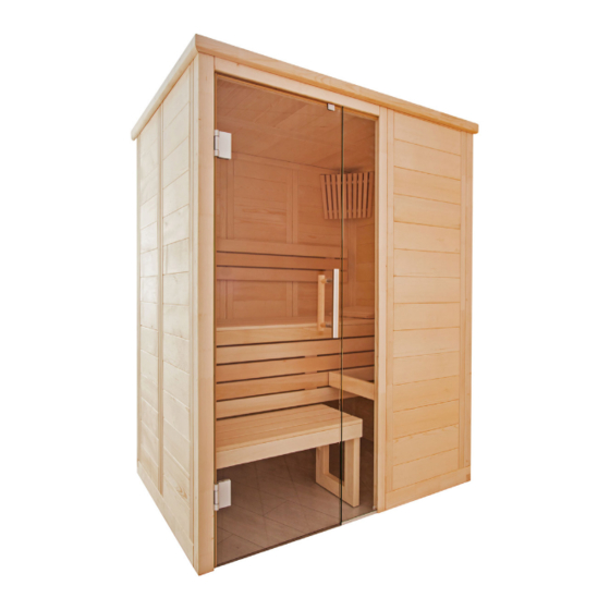
- Page 1 Solid wood sauna ALASKA MINI 160 x 110 x 204 cm INSTRUCTIONS FOR INSTALLATION AND USE English ALASKA-MN Version 07/18 Ident. no. 1-030-270...
-
Page 2: Table Of Contents
Table of Contents 1. Preparing for installation 1.1. Tools required 1.2. Maintenance and cleaning 1.3. Disposal 1.4. ALASKA MINI parts list 2. Cabin installation 2.1. Base frame installation 2.2. Wall element installation 2.3. Ceiling installation 2.4. Ventilation slit installation 2.5. Installing interior fittings 2.6. -
Page 3: Preparing For Installation
Instructions for installation and use p. 3/34 1. Preparing for installation Read these installation instructions carefully and keep them within reach when using the sauna, so that you can look up product information at any time. These installation instructions can also be found in the downloads section of our website: www.sentiotec.com/downloads. -
Page 4: Tools Required
Instructions for installation and use p. 4/34 1.1. Tools required ● Hammer with a wooden head or a mallet ● Cordless screwdriver with bits for cross-head screws and Torx ● Roller tape measure ● Drill bits with a diameter of 3 mm, 10 mm, 20 - 30 mm (for sauna heater power cable) ●... -
Page 5: Maintenance And Cleaning
Instructions for installation and use p. 5/34 1.2. Maintenance and cleaning ● The sauna should be cleaned with a damp cloth. Only use warm water – no cleaning products. ● We recommend heating the cabin once a month if the sauna is not used for a long time. -
Page 6: Alaska Mini Parts List
Instructions for installation and use p. 6/34 1.4. ALASKA MINI parts list No. of items Name Dimensions Base frame 1 Base frame 156 x 9 x 4 cm 1 Base frame 108 x 9 x 4 cm 1 Base frame 102 x 9 x 4 cm 1 Base frame 64 x 9 x 4 cm... - Page 7 Instructions for installation and use p. 7/34 No. of items Name Dimensions Interior fittings 1 Bench 147 x 62 x 9 cm 1 Foot step panel 80 x 35 x 9 cm 2 Foot step feet 43 x 33 x 4 cm 2 Foot step struts, 2 x 45°...
-
Page 8: Cabin Installation
Instructions for installation and use p. 8/34 2. Cabin installation The cabin can have a right or left set up, please note the corresponding floor plans on Page 30 and Page 31. 2.1. Base frame installation 156 cm Right floor plan 64 cm 3 mm drill bit, 3 screws 4 x 70 mm 156 cm... -
Page 9: Wall Element Installation
Instructions for installation and use p. 9/34 2.2. Wall element installation The corner posts are connected to the wall elements using Multiclips. The other wall elements are connected by tongue and groove and are screwed together. A always refers to the visible side. This is labelled on the top side of the wall elements. - Page 10 Instructions for installation and use p. 10/34 Installing corner posts with wall elements Pre-assemble the wall elements with the corner posts on the floor and then place these posts on the base frame. Insert the corner post on the wall elements, moving it downwards. When doing this, ensure that the Multiclips are correctly aligned (see below).
- Page 11 Instructions for installation and use p. 11/34 Installing wall elements The electrical element has drill holes for laying cables. For the position, see floor plans on Page 30 and Page 31. Electrical element...
- Page 12 Instructions for installation and use p. 12/34 Screwing wall elements together Check the right angle before screwing the wall elements together. Observe the tip on page 4. 3 mm drill bit, 4 screws 4 x 70 mm...
- Page 13 Instructions for installation and use p. 13/34 Corner post and post for glass...
- Page 14 Instructions for installation and use p. 14/34 Glass element Element above the door Select the element for the right floor plan...
- Page 15 Instructions for installation and use p. 15/34 3 mm drill bit, 2 screws 4 x 70 mm...
-
Page 16: Ceiling Installation
Instructions for installation and use p. 16/34 2.3. Ceiling installation Roof support slats 4 cm 3 mm drill bit, 12 screws 4 x 70 mm... - Page 17 Instructions for installation and use p. 17/34 Ceiling elements 3 mm drill bit, 10 screws 4 x 70 mm...
-
Page 18: Ventilation Slit Installation
Instructions for installation and use p. 18/34 2.4. Ventilation slit installation 3 mm drill bit, 4 screws 3 x 40 mm 2.5. Installing interior fittings Bench support slats 3 mm drill bit, 3 screws 5 x 70 mm 2 screws 4 x 60 mm... - Page 19 Instructions for installation and use p. 19/34 3 mm drill bit, 3 screws 5 x 70 mm Screws 4 x 60 mm...
- Page 20 Instructions for installation and use p. 20/34 Bench screen 4 screws 4 x 60 mm Bench...
- Page 21 Instructions for installation and use p. 21/34 Foot step 6 screws 4 x 70 mm...
- Page 22 Instructions for installation and use p. 22/34 4 screws 3.5 x 35 mm...
- Page 23 Instructions for installation and use p. 23/34 Backrests 3 mm drill bit, 3 screws 3 x 40 mm approx. 5 cm approx. 5 cm approx. 25 cm...
-
Page 24: Installing Accessories
Instructions for installation and use p. 24/34 2.6. Installing accessories Sauna lamp Insert lamp (not included in the scope of delivery) 3 mm drill bit, 2 screws 4 screws 3 x 40 mm... - Page 25 Instructions for installation and use p. 25/34 Heater protection grille Before installing the heater protection grille, drill the outlet for the heater cable in the electrical element. 12 screws 3 x 40 mm Heater protection grille can be shortened to length...
-
Page 26: Installing Glass Door
Instructions for installation and use p. 26/34 2.7. Installing glass door The bottom drill hole of the door handle is 92.4 cm high. The alignment of the fittings is achieved by adjusting / rotating both plastic inserts. - Page 27 Instructions for installation and use p. 27/34 Door handle and sleeve plate The door handles are screwed together from the inside. Insert silicone ring in the drill holes Attach plastic washers on the stainless steel handle...
-
Page 28: Installing Roof Trim
Instructions for installation and use p. 28/34 2.8. Installing roof trim Install the roof trim only after you have inserted the cable to the sauna heater and to the sauna control unit. The slat on the electrical element may possibly have to be cropped. 3 mm drill bit, 9 screws 3 x 40 mm... -
Page 29: Installing Ceiling Cover Slat
Instructions for installation and use p. 29/34 2.9. Installing ceiling cover slat Install the ceiling cover slat only after you have inserted the cable to the sauna heater and to the sauna control unit. The slat on the electrical element may possibly have to be cropped. 12 screws 3 x 40 mm... -
Page 30: Floor Plan
Instructions for installation and use p. 30/34 3. Floor plan 3.1. Right floor plan... -
Page 31: Left Floor Plan
Instructions for use for the user p. 31/34 3.2. Left floor plan... -
Page 32: Changes To The Left Floor Plan Installation
Instructions for use for the user p. 32/34 3.3. Changes to the left floor plan installation For installing corner posts and posts for the glass (page 14) Remove the Multiclips from the corner posts and the post for the glass. Use the supplied template for the new positioning of the Multiclips. - Page 33 NOTIZEN / APPUNTI / NOTES / NOTE / NOTITIES ………………………………………………….....………………………………………………………………... ……………………………………………………………..……………………………………………………………... …………………………………………………………….....………………………………………………………... …………………………………………………….....………………………………………………………………... ……………………………………………………………..……………………………………………………………... ……………………………………………………………..……………………………………………………………... ……………………………………………………………..…………………………………………………………... …………………………………………………………….....………………………………………………………... …………………………………………………………….....………………………………………………………... …………………………………………………………….....………………………………………………………... …………………………………………………………….....………………………………………………………... …………………………………………………………….....………………………………………………………..…………………………………………………………….....………………………………………………………... …………………………………………………………….....………………………………………………………... …………………………………………………………….....………………………………………………………... …………………………………………………………….....………………………………………………………... …………………………………………………………….....………………………………………………………... …………………………………………………………….....………………………………………………………... …………………………………………………………….....………………………………………………………...
- Page 34 GmbH | Division of Harvia Group | Oberregauer Straße 48, A-4844 Regau Phone +43 (0) 7672/277 20-567 | Fax -801 | info@sentiotec.com | www.sentiotec.com...
Need help?
Do you have a question about the Sentiotec ALASKA MINI and is the answer not in the manual?
Questions and answers