Table of Contents
Advertisement
Advertisement
Table of Contents

Related Manuals for Hunter TRAK


Summary of Contents for Hunter TRAK
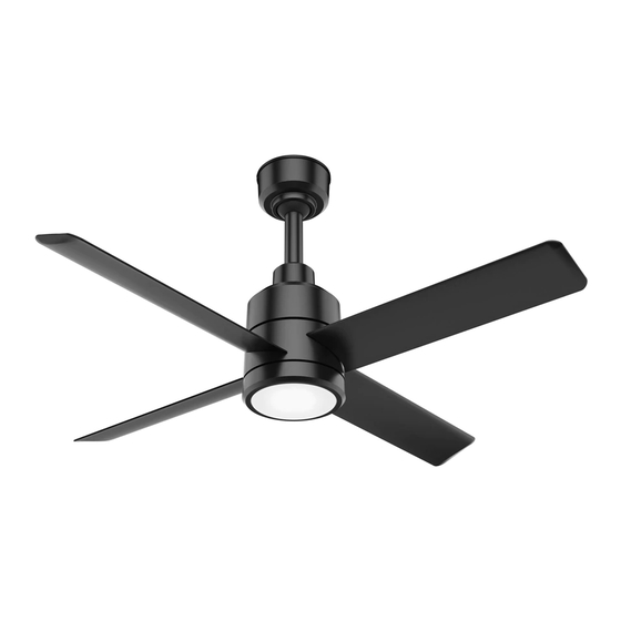
- Page 1 T R A K I N S T A L L A T I O N M A N U A L...
-
Page 2: Table Of Contents
C O N T E N T S LEGACY B EF O R E YO U B E G I N The Hunter legacy is not only SAFETY & PRECAUTIONS about quality—it’s about longevity. FAN PLACEMENT PRE-INSTALLATION We invented the modern ceiling... -
Page 3: Before You Be Gi N
SAFETY & PRECAUTIONS BEFORE YOU BE GI N Important Safety Information To prevent SERIOUS INJURY, DEATH and PROPERTY DAMAGE, you should read, understand and follow the warnings and instructions in this manual before installing or operating the fan. READ AND SAVE THESE INSTRUCTIONS. This manual must always be kept with the fan and should remain with the fan if it is transferred or sold. - Page 4 All electrical controls are configured at the factory and are ready to use. No user adjustments are available. Follow the included installation instructions when installing this device to ensure proper operation. Do not make any changes to any part of the fan without first consulting Hunter Industrial Fan.
- Page 5 7 ft-lbs. Hunter Fan provides guidelines for mounting fans; however, it is the sole responsibility of the building owner and installer to ensure the safety of the mounting system and Retention Cable, the building structure is sound, and the installation complies with all federal, state and local codes.
- Page 6 Angled Mounting A little more information on Angled Mounting: For optimum performance and appearance, a longer downrod should be used with your Hunter ceiling fan when installing on high or angled ceiling. NOTICE Fan can not be mounted on to a ceiling with an angle greater than 34°...
-
Page 7: Fan Placement
FAN PLACEMENT BE FO R E YO U BE G IN FAN PLACEMENT FAN SPACING CHART TRAK MIN - MAX 8ft (96”) 20ft - 32ft 7ft (84”) 18ft - 28ft 6ft (72”) 16ft - 24ft 5ft (60”) 14ft - 20ft... - Page 8 FAN PLACEMENT BEFO RE YOU BE GI N ALWAYS mount fan so the bottom edge of blade to the floor is at least 10 feet. Always mount fans away from the following: Sprinkler Systems Prior to installing fans, review all codes applicable to sprinkler systems and fans to ensure code compliance and refer to NFPA 13: Fire Sprinkler System Installation.
-
Page 9: Pre-Installation
PRE-INSTALLATION CHECKLIST BEFORE YOU B E GIN The location of the fan will alow for a minumum of 2 feet of blade clearance from any obstruction and at least 10 feet of clearance above the floor. If installing multiple fans, reference the fan placement chart for optimal spacing. The control panel voltage markings should match (either 100-120VAC or 220-240VAC) -
Page 10: Tools Needed
TOOLS NEEDED BEF ORE YO U BE GI N Screwdrivers Ladder Included 1/2”/ M4 Wrench Right Angled Screwdriver Blade Installation Tool Allen Wrench... -
Page 11: In The Box
IN THE BOX BE F ORE YO U B E GI N FAN COMPONENTS E (1) Downrod K (K1)Data Cable Connector; F (1) Motor (K2) Power Cable Connector G (4) Blades L (1) Remote Control Assembly H (1) Ceiling Bracket M Hanger Bracket Guide I (1) Canopy N (1) Installation Manual... -
Page 12: In Stal L Ati On
PREPARATION IN STAL L ATI ON If you have a building management system you will need to set the dip switches for your fan IP address. Use the chart to set your switches. On is 1. 0 is the dip switch in the off position. Bit 1 Bit 2 Bit 3... -
Page 13: Step 2: Ceiling Bracket
(H) and set aside. Remove any existing bracket prior to installation. Only use the provided Hunter ceiling bracket that came in your fan’s box. WARNING To avoid possible electrical shock, before installing your fan, disconnect the power by turning off the circuit breakers to the outlet box associated with the wall switch location. -
Page 14: Step 3: Downrod
DOWNROD IN STAL L ATION Place the preassembled Place the bottom of the downrod Connect the communication Attached the secondary hanging cable to the fan by threading the downrod (E) through the into the bracket of the fan while cable from the downrod to the cable eye through the upper slot canopy(I) and upper motor aligning the holes. -
Page 15: Step 4: Motor Assembly
MOTOR ASSEMBLY IN STALL ATI ON CRUSH HAZARD. To prevent serious injury or death, ALWAYS attach the Retention Cable to the fan motor and secure to the building structure on EVERY fan. Lower the upper motor Place hanger guide (M) through the Lift motor assembly and insert hanger To secure the motor assembly housing (J) and twist... -
Page 16: Step 5: Retention System
RETENTION SYSTEM INSTAL L ATI ON CRUSH HAZARD. To prevent serious injury or death, ALWAYS attach the Retention Cable to the fan motor and secure to the building structure on EVERY fan. NOTICE Leave approximatlely 3” of slack in the wire and the cable, at the top of the downrod opening. -
Page 17: Step 6: Wiring
WIRING INSTALLATION Electric Shock Hazard Electric Shock Hazard. To prevent serious injury or death: • BEFORE installing or servicing your fan, ALWAYS disconnect the power by turning off the circuit breaker or breakers to the fan locations and confirm Lockout/Tagout procedures are in place. •... -
Page 18: Step 7: Mounting
MOUNTING INSTALLATION Position data connector, power connector, and excess wiring inside the ceiling bracket. Lift the canopy and align the single ridge on the canopy with the single ridge on the ceiling gasket. Twist clockwise to secure. The singe ridge of the canopy will align with the two ridges of the ceiling gasket. -
Page 19: Step 8: Blades
BLADES INSTALLATION Match blade with colored circle to blade iron with the Insert a screw into the remaining two Remove installation tool and insert a same colored circle. Slide blade over blade iron and screw holes. Tighten both screws screw into the remaining screw hole align the blade screw holes with the blade iron holes. -
Page 20: Step 9: Remote Control
REMOTE CONTROL INS TAL L ATI ON Press = Fan Off To access the battery compartment, remove the Single Press = Set Fan to Speed 1 small Phillips head screw that secures the battery Press Twice= Set Fan to Speed 2 door to the transmitter assembly. -
Page 21: R Ef Er E Nc E
MAINTENANCE RE FE RE N C E Electric Shock Hazard Electric Shock Hazard To prevent serious injury or death: • BEFORE performing maintenance or service, ALWAYS disconnect the power by turning off the circuit breaker or breakers to the fan locations and confirm Lockout/Tagout procedures are in place. •... -
Page 22: Troubleshooting
5. You will see LED blink once for command sent confirmation. Release the power button. For situations beyond the scope of this Guide, 180 Threet Industrial Road Suite 120, Smyrna, TN 37167 please call our Technical Service Department at ©2020 Hunter Fan Company. All rights reserved. HUNTERFAN.COM MI001-01 020620 1-844-593-3267 (FANS).
Need help?
Do you have a question about the TRAK and is the answer not in the manual?
Questions and answers