Advertisement
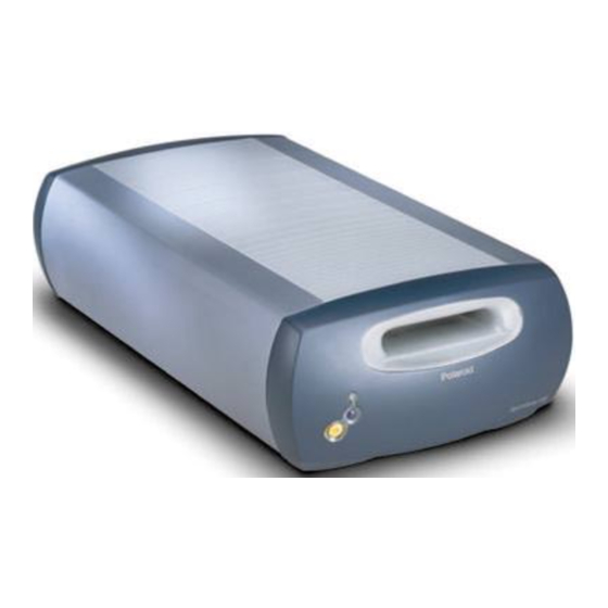
Exchange of the original Polaroid SprintScan 120 Eprom
Safety instructions!
First please remove all external cables from the device.
Never open your Polaroid SprintScan while it is attached to a power supply.
With devices attached to electricity mains mortal danger exists!
Ground yourselves.
If you do not own a grounding bracelet, please touch a heating element or other grounded
structure before touching any chips or circuit board.
Read this entire manual before you start disassembleing your scanner.
The installation of the chip takes place on your own responsibility.
Opening the casing
First you have to remove the screws fastening the case.
Carefully turn your Polaroid SprintScan 120 on it's back.
Start with the screw for the front cover (central screw towards the front).
Before you remove the other screws turn the dvice back on it's feet.
Attention: the rear cover screw does not have to be removed.
© LaserSoft Imaging
1/6 pages
Advertisement
Table of Contents

Related Manuals for Polaroid SprintScan 120


Summary of Contents for Polaroid SprintScan 120
- Page 1 Exchange of the original Polaroid SprintScan 120 Eprom Safety instructions! First please remove all external cables from the device. Never open your Polaroid SprintScan while it is attached to a power supply. With devices attached to electricity mains mortal danger exists! Ground yourselves.
- Page 2 Carefully remove the front cover. The cover is held by two plastic hooks. Watch the connection cable. Write down the color of the upmost cable strand. Now carefully disconnect the cable from the frontcover. Turn the device back on its rear and remove the six side-screws holding the main cover. ©...
- Page 3 Now turn the scanner around on it's feet another time. Remove the rear screws. Now you can carefully slide the main casing forwards. © LaserSoft Imaging 3/6 pages...
- Page 4 Exchange of the firmware The firmware chip is located on the side circuit board. Carefully raise the chip by placing an appropriate tool between the chip and the chip holder. Alternately place the tool under the left and right side so the chip is raised evenly. (A wooden spatula is best suited for this.
- Page 5 Make sure you position you new chip correctly. The small dot on the chip has to be aligned to the slanted corner of the chipholder. Prüfen Sie, dass alle Beine des neuen Chip gerade sind. Before inserting the chip check if any legs of the chip are bent. Correct any bent legs before proceding.
- Page 6 Reassembly Slide the main casing back on and fasten the rear screws. Turn the scanner on it's back and fasten the side screws holding the main casing. Turn the scanner back around and connect the cable to the front cover. Confirm that the color coding of the cable is corosponding to your notes.
Need help?
Do you have a question about the SprintScan 120 and is the answer not in the manual?
Questions and answers