Riello GAS 4 Installation, Use And Maintenance Instructions
Forced draught gas burners
Hide thumbs
Also See for GAS 4:
- Installation, use and maintenance instructions (20 pages) ,
- Installation, use and maintenance instructions (13 pages) ,
- Installation, use and maintenance instructions (17 pages)
Table of Contents
Advertisement
Quick Links
Istruzioni per installazione, uso e manutenzione
Montage und Bedienungs Anleitung
Installation, use and maintenance instructions
Manuel d'entretien
Bruciatori di gas ad aria soffiata
I
Gas-Gebläsebrenner
D
Forced draught gas burners
GB
Brûleurs gaz à air soufflé
F
Funzionamento monostadio
Einstufiger Betrieb
One stage operation
Fonctionnement à 1 allure
CODICE - CODE
3751917 - 3751918
3751617
3751717
3751817
MODELLO - MODELL
MODEL - MODELE
GAS 3
GAS 4
GAS 5
GAS 6
TIPO - TYP
TYPE
519 T1
516 T1
517 T1
518 T1
2915915 (4) - 08/2012
Advertisement
Table of Contents

Related Manuals for Riello GAS 4


Summary of Contents for Riello GAS 4
- Page 1 Fonctionnement à 1 allure MODELLO - MODELL TIPO - TYP CODICE - CODE MODEL - MODELE TYPE 3751917 - 3751918 GAS 3 519 T1 3751617 GAS 4 516 T1 3751717 GAS 5 517 T1 3751817 GAS 6 518 T1 2915915 (4) - 08/2012...
- Page 3 GAS 3 - 4 - 5 - 6 Questi prodotti sono conformi alle seguenti Norme Tecniche: DIN 4788 (02. 1990) (solo per GAS 3) EN 676 (GAS 4 - 5 - 6) EN 12100 e secondo quanto disposto dalle Direttive Europee:...
- Page 4 GAS 3 - 4 - 5 - 6 These products are in compliance with the following Technical Standards: DIN 4788 (02. 1990) (olny for GAS 3) EN 676 (GAS 4 - 5 - 6) EN 12100 and according to the European Directives:...
-
Page 5: Table Of Contents
INDICE INHALT DATI TECNICI ....... . . pagina 4 TECHNISCHE ANGABEN ......Seite 5 Accessori . -
Page 6: Dati Tecnici
DATI TECNICI MODELLO GAS 3 GAS 4 GAS 5 GAS 6 TIPO 519 T1 516 T1 517 T1 518 T1 POTENZA 130 - 350 185 - 465 325 - 660 525 - 1050 Mcal/h 112 - 301 160 - 400... -
Page 7: Technische Angaben
TECHNISCHE ANGABEN MODELL GAS 3 GAS 4 GAS 5 GAS 6 519 T1 516 T1 517 T1 518 T1 LEISTUNG 130 - 350 185 - 465 325 - 660 525 - 1050 Mcal/h 112 - 301 160 - 400 280 - 570... -
Page 8: Technical Data
TECHNICAL DATA MODEL GAS 3 GAS 4 GAS 5 GAS 6 TYPE 519 T1 516 T1 517 T1 518 T1 OUTPUT 130 - 350 185 - 465 325 - 660 525 - 1050 Mcal/h 112 - 301 160 - 400... -
Page 9: Données Techniques
DONNÉES TECHNIQUES MODELE GAS 3 GAS 4 GAS 5 GAS 6 TYPE 519 T1 516 T1 517 T1 518 T1 PUISSANCE 130 - 350 185 - 465 325 - 660 525 - 1050 Mcal/h 112 - 301 160 - 400... -
Page 10: Accessori
L = 185 L1 = 320 mm • GAS 3 (A) KIT PER ALLUNGARE LA TESTA DI COD. 3000606 L = 187 L1 = 320 mm • GAS 4 COMBUSTIONE COD. 3000607 L = 207 L1 = 365 mm • GAS 5... -
Page 11: Accessories
ZUBEHÖR (auf Wunsch) ACCESSORIES (optional) ACCESSOIRES (sur demande) (A) KIT ZUR VERLÄNGERUNG DES FLAMM- (A) KIT FOR LENGTHENING THE COMBUS- (A) KIT POUR ALLONGER LA TETE DE KOPFES TION HEAD COMBUSTION = Standardlänge = Standard length = Longueur standard L1 = Mit Kit erreichbare Länge L1 = Length obtainable with the kit L1 = Longueur pouvant être obtenue avec le kit... -
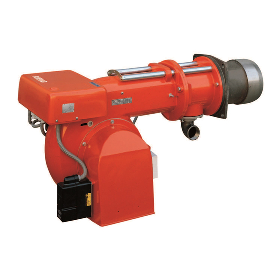
Page 12: Descrizione Bruciatore
L'ingombro del bruciatore aperto è indicato dalla quota I. CORREDO 1 - Flangia per rampa gas GAS 3 1 - Guarnizione per flangia GAS 4 8 - Viti GAS 5 1 - Schermo termico GAS 6 1045 1 - Istruzione... -
Page 13: Burner Description
BRENNERBESCHREIBUNG (A) BURNER DESCRIPTION (A) DESCRIPTION BRULEUR (A) 1 Gleitschienen zur Öffnung des Brenners und 1 Slide bars for opening the burner and 1 Guides pour ouverture brûleur et inspection für die Kontrolle des Flammkopfs inspecting the combustion head de la tête de combustion 2 Flammkopf 2 Combustion head 2 Tête de combustion... -
Page 14: Campi Di Lavoro
• l'asse delle pressioni in cam. comb. 0 + 7 mbar • la curva di massima pressione in cam. comb. GAS 4 Se il bruciatore sviluppa una potenza di 250 kW D289 ad una pressione in camera di combustione di 5 mbar, il punto di lavoro si trova sulla curva di massima pressione. -
Page 15: Firing Rates
GELBEREICHE FIRING RATES PLAGES DE PUISSANCE (Diagramme nebenstehend) (graphs to side) (diagrammes ci- Die Leistung des Brenners wird innerhalb des The burner delivery must be selected within the contre) Le débit du brûleur doit être choisi dans la plage Feldes aus der nebenstehenden Diagramme area of the adjacent diagram. -
Page 16: Caldaie Di Prova
CALDAIA DI PROVA (A) I campi di lavoro di pagina 6 sono stati ricavati in speciali caldaie di prova secondo la norma EN 676. Riportiamo in (A) diametro e lunghezza della ca- mera di combustione di prova. Esempio: potenza 1500 Mcal/h: diametro 80 cm - lunghezza 2,5 m PRESSIONE GAS La pressione del gas in funzione della potenza... -
Page 17: Test Boiler
PRÜFKESSEL (A) TEST BOILER (A) CHAUDIERE D'ESSAI (A) Die Regelbereiche wurden an speziellen Prüf- Les plages de puissance de la page 6 ont été The firing rates on page 6 were set in relation to kesseln entsprechend Norm EN 676 ermittelt. établies sur des chaudières d'essai spéciales, special test boilers, according to regulation EN In (A) sind Durchmesser und Länge der Prüf-... -
Page 18: Installazione
Ricordiamo che le lunghezze disponibili sono: Boccaglio GAS 3 GAS 4 GAS 5 GAS 6 L mm Accorciato Standard Allungato • Per le caldaie con giro dei fumi anteriore... -
Page 19: Installation
Three different blast tube lengths are availa- Rappelons que les longueurs disponibles ble: sont: Flammrohr GAS 3 GAS 4 GAS 5 GAS 6 L mm Blast tube Buse GAS 3 GAS 4 GAS 5 GAS 6 GAS 3 GAS 4 GAS 5 GAS 6... -
Page 20: Regolazione Testa Di Combustione
REGOLAZIONE TESTA COMBU- BRUCIATORE APERTO - GEÖFFNETER BRENNER STIONE BURNER OPEN - BRÛLEUR OUVERT La regolazione della testa di combustione dipende unicamente dalla potenza sviluppata dal bruciatore. Perciò, prima di regolare la testa di combu- stione, bisogna fissare questo valore. Sono previste due regolazioni della testa: quella del gas e quella dell'aria. -
Page 21: Combustion Head Setting
EINSTELLUNG DES FLAMMKOPFS SETTING THE COMBUSTION HEAD REGLAGE TETE DE COMBUSTION Die Einstellung des Flammkopfs ist einzig von Combustion head adjustment depends exclu- Le réglage de la tête de combustion dépend uni- der vom Brenner entwickelten Leistung abhän- sively on output generated by the burner. quement de la puissance développée par le brû- gig. -
Page 22: Linea Alimentazione Gas
= RAMPE GAS L: A1 e A2 C mbar = COMPONENTI RAMPA GAS L (A1) = PERDITA DI CARICO RAMPA GAS L GAS 3 GAS 4 GAS 5 GAS 6 Ø (A1) alla potenza massima del bruciatore LEGENDA TABELLA (A) 3/4”... -
Page 23: Gas Line
GASZULEITUNG GAS LINE LIGNE ALIMENTATION GAZ • The gas train can enter the burner from the • Die Armatur kann je nach Bedarf von rechts • La rampe peut arriver par la droite ou par la right or left side, depending on which is the bzw. -
Page 24: Impianto Elettrico
IMPIANTO ELETTRICO GAS 3 - 4 eseguito in fabbrica IMPIANTO ELETTRICO ESEGUITO IN FABBRICA WERKSEITIG AUSGEFÜHRTE ELEKTROANLAGE SCHEMA (A) ELECTRICAL EQUIPMENT FACTORY-SET Bruciatori GAS 3 - 4 (monofase) INSTALLATION ELECTRIQUE REALISEE EN USINE SCHEMA (B) Bruciatori GAS 5 - 6 (trifase) •... -
Page 25: Electrical System
ELEKTROANLAGE ELECTRICAL SYSTEM INSTALLATION ELECTRIQUE werkseitig ausgeführt as set up by the manufacturer réalisée en usine SCHEMA (A) LAYOUT (A) SCHEMA (A) Brenner GAS 3 - 4 (einphasig) Burners GAS 3 - 4 (single-phase) Brûleurs GAS 3 - 4 (monophasés) SCHEMA (B) LAYOUT (B) SCHEMA (B) - Page 26 COLLEGAMENTI ELETTRICI FISSAGGIO CAVI - KABELBEFESTIGUNG - CABLE SECURING - FIXATION BABLES Eseguito dall'installatore. GAS 3 - 4 GAS 5 - 6 Usare cavi flessibili secondo norma EN 60 335-1: • se sotto guaina di PVC almeno tipo H05 VV-F; •...
- Page 27 ELEKTROANLAGE ELECTRICAL SYSTEM RACCORDEMENT ELECTRIQUE Vom Installateur auszuführen. Effectué par l'installateur. Installer-set. Gemäß Norm EN 60 335-1 biegsame Kabel ver- Utiliser des câbles flexibles selon la norme EN Use flexible cables according to EN 60 335-1 wenden: 60 335-1: Regulations: •...
- Page 28 SCHEMA (A) - Alimentazione trifase IMPIANTO ELETTRICO ESEGUITO DALL’INSTALLATORE Allacciamento elettrico bruciatori GAS 5 - 6 VOM INSTALLATEUR AUSZUFÜHRENDE ELEKTROINSTALLATION senza controllo tenuta valvole gas. ELECTRICAL CONNECTION OF BURNER BY INSTALLER RACCORDEMENT BRULEUR EFFECTUE PAR L’ INSTALLATEUR SCHEMA (B) - Alimentazione trifase GAS 5 - 6 Allacciamento elettrico bruciatori GAS 5 - 6 con controllo tenuta valvole gas VPS.
- Page 29 SCHEMA (A) - Dreiphasenspeisung LAYOUT (A) - The GAS 5 - 6 Models electrical SCHEMA (A) - Alimentation triphasée Elektroanschluß der Brenner GAS 5 - 6 ohne connection three-phase power supply with- Branchement électrique brûleurs GAS 5 - 6 Dichtheitskontrolle der Gasventile. out leak detection control device.
-
Page 30: Regolazioni Prima Dell'accensione
REGOLAZIONI PRIMA DELL'ACCENSIONE PRESSOSTATO ARIA La regolazione della testa di combustione, aria e LUFT-DRUCKWÄCHTER AIR PRESSURE SWITCH gas, è già stata descritta a pag. 18. PRESSOSTAT AIR Altre regolazioni da fare sono: - Aprire le valvole manuali poste a monte della rampa del gas. -
Page 31: Adjustments Before Firing
EINSTELLUNGEN VOR DER ZÜNDUNG ADJUSTMENTS BEFORE FIRST FIRING REGLAGES AVANT L'ALLUMAGE Die Einstellung des Flammkopfs, von Luft und Le réglage de la tête de combustion, air et gaz, Adjustment of the combustion head, and air and Gas, ist bereits auf Seite 19 beschrieben a déjà... -
Page 32: Regolazione Bruciatore
REGOLAZIONE BRUCIATORE Per ottenere una regolazione ottimale del bruci- atore è necessario effettuare l'analisi dei gas di scarico della combustione all'uscita della caldaia. Regolare in successione: (con rampa gas secondo norma EN 676) 1 - Potenza all'accensione 2 - Potenza massima bruciatore 3 - Pressostato aria 4 - Pressostato gas di minima 1 - POTENZA ALL’ACCENSIONE... -
Page 33: Burner Calibration
BRENNEREINSTELLUNG BURNER CALIBRATION REGLAGE BRULEUR Für die optimale Einstellung des Brenners soll- The optimum calibration of the burner requires Pour obtenir un réglage optimal du brûleur, il ten die Abgase am Kesselausgang analysiert an analysis of the flue gases at the boiler outlet. faut effectuer l'analyse des gaz d'échappement werden. -
Page 34: Potenza Massima
2 - POTENZA MASSIMA BRUCIATORE PRESSOSTATO ARIA LUFT-DRUCKWÄCHTER Regolazione gas MAX AIR PRESSURE SWITCH Misurare la portata del gas. PRESSOSTAT AIR - Se bisogna ridurla, chiudere un poco la valvola gas di 2° stadio. - Se bisogna aumentarla, prima aprire tutta la valvola gas di 2°... -
Page 35: Maximum Output
2 - HÖCHSTLEISTUNG DES BRENNERS 2 - MAXIMUM OUTPUT OF THE BURNER 2 - PUISSANCE MAXIMUM DU BRULEUR Réglage gaz MAX Gaseinstellung auf Höchstwert MAX gas setting Mesurer le débit du gaz. Gasdurchsatz messen. Measure gas delivery. - S'il faut la réduire, fermer un peu la vanne du - Falls er vermindert werden muß, das Gasventil - If it is to be reduced, close the 2nd stage gas gaz de 2ème allure. -
Page 36: Funzionamento Bruciatore
FUNZIONAMENTO BRUCIATORE ACCENSIONE REGOLARE ORDNUNGSGEMÄSSES ZÜNDEN (n° = secondi dall’istante 0) (n° = Sekunden ab Zeitpunkt 0) AVVIAMENTO BRUCIATORE (A) (con rampa gas a norma EN 676) NORMAL FIRING ALLUMAGE REGULIER (n° = seconds from istant 0) (n° = secondes à partir de l’istant 0) •... -
Page 37: Burner Operation
BRENNERBETRIEB BURNER OPERATION FONCTIONNEMENT BRULEUR ANFAHREN DES BRENNERS (A) BURNER STARTING (A) DEMARRAGE BRULEUR (A) (Gasarmaturen gemäß Norm EN 676) (with gas train according to EN 676 Regulations) (avec rampe gaz selon la norme EN 676) • 0s: Fernsteuerung TL schließen. •... -
Page 38: Controlli Finali
CONTROLLI FINALI (con bruciatore funzio- APERTURA BRUCIATORE - BRENNERÖFFNUNG nante) OPENING THE BURNER - OUVERTURE BRULEUR • Scollegare un filo del pressostato gas di minima: • Aprire il telecomando TL: • Aprire il telecomando TS: il bruciatore deve fermarsi • Scollegare il filo comune P del pressostato aria: •... -
Page 39: Final Checks
ENDKONTROLLEN FINAL CHECKS CONTROLES FINAUX (bei Brenner in Betrieb) (with burner running) (brûleur en fonction- • Einen Draht des Gas-Mindestdruckwächters • Disconnect one of the wires on the minimum nement) abtrennen: gas pressure switch: • Débrancher un fil du pressostat de seuil mini- •... -
Page 40: Inconvenienti - Cause - Rimedi
INCONVENIENTI - CAUSE - RIMEDI Segnale Inconveniente Causa probabile Rimedio consigliato 2 lampeggi Superata la preventila- 1 - L'elettrovalvola di funzionamento fa passare poco Aumentarlo zione ed il tempo di sicu- rezza il bruciatore va in blocco senza apparizione 2 - Una delle due elettrovalvole non si apre..Sostituire di fiamma. -
Page 41: Normale Funzionamento / Tempo Di Rilevazione Fiamma
Segnale Inconveniente Causa probabile Rimedio consigliato Nessun lampeggio Il bruciatore non si avvia 36 - Manca l'energia elettrica ....Chiudere interruttori Controllare colle- gamenti 37 - Telecomando limite o di sicurezza aperto. -
Page 42: Diagnostica Programma Di Avviamento
DIAGNOSTICA PROGRAMMA DI AVVIAMENTO Durante il programma di avviamento, le indicazioni sono esplicate nella seguente tabella: TABELLA CODICE COLORE Sequenze Codice colore Preventilazione Fase di accensione Funzionamento con fiamma ok Funzionamento con fiamma debole Alimentazione elettrica inferiore a ~ 170V Blocco Luce estranea Spento... -
Page 43: Störungen - Ursachen - Abhilfen
STÖRUNGEN - URSACHEN - ABHILFEN Signal Störungen Mögliche Ursache Empfohlene Abhilfe 2 Blinken Störabschaltung des 1 - Ungenügender Gasfluß durch das Magnetventil. Steigern Brenners nach der Vorbe- 2 - Eines der beiden Magnetventile öffnet sich nicht. Austauschen lüftung, und der Sicher- heitszeit ohne 3 - Gasdruck zu gering . -
Page 44: Normaler Betrieb / Flammendetektionszeit
Signal Störungen Mögliche Ursache Empfohlene Abhilfe Kein Blinken Brenner geht nicht an 36 - Kein Strom ......Schalter schließen - Anschlüsse kon- trollieren 37 - Eine Grenz-oder Sicherheitsfernsteuerung offen Einstellen oder auswechseln... -
Page 45: Diagnostik Betriebsablauf
DIAGNOSTIK BETRIEBSABLAUF Die Bedeutung der verschiedenen Anzeigen während des Anlaufprogramms ist in folgender Tabelle erklärt: FARBCODETABELLE Sequenzen Farbcode Vorspülung Zündung Betrieb mit Flamme OK Betrieb mit schwachter Flamme Stromversorgung unter ~ 170V Störabschaltung Fremdlicht gelb grün Erläuterung: DIAGNOSTIK BETRIEBSSTÖRUNGEN Das mitgelieferte Steuergerät hat eine Diagnosefunktion, mit der die möglichen Ursachen von Betriebsstörungen leicht auf- findbar sind (Anzeige: ROTE LED). -
Page 46: Fault - Probable Cause - Suggested Remedy
FAULT - PROBABLE CAUSE - SUGGESTED REMEDY Signal Problem Possible cause Recommended remedy 2 blinks Once the pre-purging 1 - The operation solenoid lets little gas through . . . Increase phase and safety time have passed, the burner 2 - One of the two solenoid valves does not open. . Replace goes into lockout without the appearance of the 3 - Gas pressure too low . -
Page 47: Normal Operation / Flame Detection Time
Signal Problem Possible cause Recommended remedy No blink The burner does not start 36 - No electrical power supply ....Close all switches - Check connec- tions 37 - A limiter or safety control device is open. -
Page 48: Burner Start-Up Cycle Diagnostics
BURNER START-UP CYCLE DIAGNOSTICS During start-up, indication is according to the followin table: COLOUR CODE TABLE Sequences Colour code Pre-purging Ignition phase Operation, flame ok Operating with weak flame signal Electrical supply lower than ~ 170V Lock-out Extraneous light Yellow Green Key: OPERATING FAULT DIAGNOSTICS... -
Page 49: Inconvénients - Causes - Rimèdes
INCONVÉNIENTS - CAUSES - RIMÈDES Signal Inconvénient Cause probable Remède conseillé 2 clignotements Après la préventilation et 1 - L'électrovanne de fonctionnement fait passer. . . Augmenter le temps de sécurité, le peu de gaz. brûleur se met en sécurité 2 - Une des deux électrovannes ne s'ouvre pas. -
Page 50: Fonctionnement Normal / Temps De Détection Flamme
Signal Inconvénient Cause probable Remède conseillé Pas de clignotement Le brûleur ne démarre 36 - Absence de courant électrique ....Fermer interrupteurs Contrôler raccor- dements 37 - Télécommande de limite ou de sécurité ouverte Régler ou remplacer 38 - Fusible de ligne interrompu. -
Page 51: Diagnostics Cycle De Démarrage
DIAGNOSTIC CYCLE DE DÉMARRAGE Pendant le programme de démarrage, les indications sont expliqées dans le tableau suivant: TABLEAU CODE COULEUR Séquences Code couleur Préventilation Phase d’allumage Fonctionnement avec flamme ok Fonctionnement avec signal de flamme faible Alimentation électrique inférieure à ~ 170V Sécurité...
Need help?
Do you have a question about the GAS 4 and is the answer not in the manual?
Questions and answers