Moller Medical LiquoGuard 7 Instruction Manual
Csf drainage pump
Hide thumbs
Also See for LiquoGuard 7:
- Manual (2 pages) ,
- Quick start manual (9 pages) ,
- Manual (20 pages)
Table of Contents
Advertisement
Quick Links
Advertisement
Table of Contents

Related Manuals for Moller Medical LiquoGuard 7


Summary of Contents for Moller Medical LiquoGuard 7
- Page 1 CSF drainage pump...
- Page 2 IMPORTANT READ CAREFULLY BEFORE USE KEEP THESE INSTRUCTIONS FOR FUTURE CONSULTATION © Möller Medical GmbH All rights reserved. No parts of this document may be reproduced or translated in any form or by any means without the prior written permission of Möller Medical GmbH. The latest version of the information, specifications and illustrations provided in this instruction manual is indicated by the version number on the last page.
-
Page 3: Table Of Contents
Table of contents Table of contents General safety instructions ................9 Explanation of the safety symbols used ............9 1.1.1 Symbols used in instruction manual ............ 9 1.1.2 Symbols appearing on the device ............9 ® 1.1.3 Symbols appearing on the LiquoGuard 7 display ...... - Page 4 General safety instructions 3.8.3 Softkeys .................... 33 Installation and startup ................37 Transport and storage instructions ..............37 Unpacking the device and inspecting delivery ..........37 ® Operating the LiquoGuard 7 ................. 37 4.3.1 Hanging onto a standard rail ............. 38 4.3.2 Installation on an infusion stand ............
- Page 5 Table of contents 6.2.1 General ..................... 54 6.2.2 Flow ....................55 6.2.3 Pulsation ................... 57 6.2.4 Parenchymal/Tip sensor ..............59 6.2.5 Monitor/Nurse Call ................59 6.2.6 CPP/cMAP Sensor ................59 Setup ......................59 6.3.1 Language ..................59 6.3.2 Display ....................60 6.3.3 Config ....................
- Page 6 General safety instructions 9.2.2 Application data ................92 9.2.3 Set marker ..................94 9.2.4 History ....................95 9.2.5 Printing ..................... 97 Presettings ....................99 ® 9.3.1 Editing the LiquoGuard 7 presettings ..........99 9.3.2 Copy drainage settings to tubing set ..........101 Printing .......................
- Page 7 Table of contents 10.5.3 After MRI imaging ................128 10.6 Accessories ....................129 Index ........................134 Page 7 of 136...
- Page 8 Page 8 of 136...
-
Page 9: General Safety Instructions
General safety instructions 1 General safety instructions 1.1 Explanation of the safety symbols used In this instruction manual, visual symbols are used to highlight important instructions . These references are prerequisites for preventing hazards to patients and operating personnel, as well for avoiding damages or malfunctioning of the device. -
Page 10: Symbols Appearing On The Liquoguard
General safety instructions Backup battery Parenchymal or tip sensor connection (compatiple with Philips M1006B invasive pressure module connection). Patient monitor output (compatible with Edwards TruWave) “ON” for a part of equipment “OFF” for a part of equipment Tubing set connection Pcsf Connection for I/O connector In/Out... - Page 11 General safety instructions Drainage quantity counter active. Message when the set drainage quantity is reached. All physiological alarms displayed and emitted. All physiological alarms are suppressed, with the remaining time displayed until the alarm sounds again 5:00 Keypad lock inactive Keypad lock active Main battery charge Presentation mode ready...
-
Page 12: Symbols Indicated On The Retail Packaging
General safety instructions 1.1.4 Symbols indicated on the retail packaging Consult instructions for use Catalog number Batch code Serial number (the 4 digits indicate the ear and month of manufacture in YYMM format) Use by date YYYY-MM-DD Sterilized using ethylene oxide Not suitable for use with MRI Limited suitability of tubing set for use with MRI. - Page 13 General safety instructions Date of manufacture YYYY-MM-DD Total length Blood pressure, invasive measurement Follow the instructions for use Quantity Type BF applied part Keep away from sunlight Caution! Observe transport and storage conditions. Attention: Under US Federal law, this device may be sold only to a physician or ordered by a physician.
-
Page 14: Explanation Of The Conventions Applied
General safety instructions 1.2 Explanation of the conventions applied Various typefaces are used in these instructions for easier reference. Typeface Application Bold and italics Buttons used in operating procedures Dialog fields and submenus in running text. MALL CAPITALS Italics Device options, buttons and references to chapters and sections in running text. -
Page 15: Owner´s Duty Of Care
General safety instructions 1.5 Owner´s duty of care The owner of the device must accept responsibility for the proper operation of the medical device. The user is obliged to fulfill all duties in accordance with the regulatory requirements and is fully responsible for all activities when using medical devices. Only qualified ®... -
Page 16: Additional Accessories
General safety instructions Keep cables away from sources of heat. This is to prevent the insulation from melting, potentially causing a fire or electrocution. Do not force the connector plug into the socket. Do not pull on the cable when removing the plug. If necessary, loosen the plug interlock to remove it. -
Page 17: Declaration On Dehp
General safety instructions 1.8 Declaration on DEHP ® The LiquoGuard 7 tubing sets do not contain any bis (2-ethylhexyl) phthalate (DEHP). 1.9 Application during defibrillation and for electrosurgical devices Do not touch the patient, table or instruments during defibrillation. The measurement accuracy can be impaired during defibrillation. -
Page 18: Purpose
Purpose 2 Purpose ® The Möller Medical GmbH LiquoGuard 7 CSF drainage pump is a pressure-controlled ® peristaltic pump. The LiquoGuard 7 Drainage Set is a sterile single-use accessory ® ® designed to be used only with the LiquoGuard 7 CSF drainage pump. The LiquoGuard ®... -
Page 19: Indications For Permanent Csf Drainage
Purpose Non-communicating hydrocephalus CSF drainage is temporarily impaired by a partial or complete occlusion of the CSF draining paths. This case can arise with masses (tumors, cysts, hemorrhage, congenital malformation) near the foramen of Monro, of the 3rd ventricle, the aqueduct, the 4th ventricle or the foramen of Monro and the foramina of Luschka. -
Page 20: Combination With Other Products, Catheters And Cannulas
Purpose Myelitis Nosocomial infection Cerebral hemorrhage Epidural hematoma Spinal cord injury Nerve injury Cone and cauda injury Back pain Cerebral swelling Slit ventricles Overdrainage Underdrainage Disconnection Bent tubes ... -
Page 21: Patient Population & Residual Risk
Purpose 2.6 Patient population & residual risk There are no restrictions with regard to the patient population. The device can be used on patients from any age group, with any health condition, and from any ethnic group. The patient does not operate the device. ®... -
Page 22: Product Description
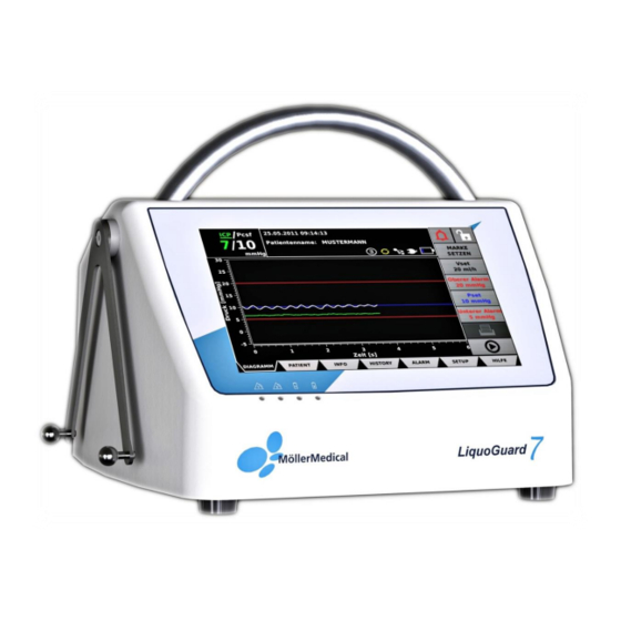
Product description 3 Product description Carrying Bag holder handle folded up Universal bracket ® Figure 1: View of the LiquoGuard 7 from the left. Pump Touchscreen LEDs ® Figure 2: View of the LiquoGuard 7 from above Page 22 of 136... -
Page 23: Touchscreen
Product description 3.1 Touchscreen ® User input in the LiquoGuard 7 is performed via the touch-sensitive, resistive surface (Touchscreen, see Figure 2) of the display. Use a finger or suitable input pen to make entries. To select a button on the screen, apply light pressure on the touchscreen in the area of the button. -
Page 24: Connection Options
Product description Symbol Function Description Main This LED flashes red as soon as an alarm condition or system alarm failure is detected (see page 69) or when the battery charge is lower than 20%. Even if Alarm Pause is activated, the LED indicates the presence of a valid alarm condition. -
Page 25: User Interface
Product description ® In addition to the On/Off switch (I 0), which is used to switch the LiquoGuard 7 on and off, the following connection options are also located on the right-hand side of the housing (see Figure 4): Parenchymal or tip sensor connection (compatible with the Philips M1006B Invasive Pressure Module connection;... -
Page 26: Tab Bar
Product description 3.7.1 Tab bar ® All information and input fields for the LiquoGuard 7 can be found under several multi-level dialog fields. Access dialog fields by selecting the relevant button on the tab bar (see Figure 5). The active dialog field appears in black on the tab bar. If no entry is made in the ®... -
Page 27: Softkeys
Product description ANGUAGE ISPLAY ONFIG Device settings PERATION ETUP ERVICE RESETTINGS ETWORK 3.7.2 Softkeys Use the softkeys in the right-hand margin of the screen (see Figure 5) to change the relevant values in the D dialog field. - Page 28 Product description 3.7.3.2 Numeric keyboard screen Use the numeric keyboard screen (see Figure 7) to enter numeric values. Make sure that a point is used to separate hours and minutes when entering the time. Enter the required value via the digits on the numeric keyboard screen. To delete numbers, press the <= button.
-
Page 29: Diagram Dialog Field
Product description Figure 9: Changing the year on the calendar. Changing the month Select the Month appearing at the top of the calendar. A drop-out menu will appear on the calendar (see Figure 10). Select the month required from the drop-out menu. To save the entry, select the desired calendar day. -
Page 30: Diagram
Product description 3.8.1 Diagram The diagram shows the current measurement curves (see Figure 11) Curve description Curve color Explanation Pcsf White CSF pressure measured on the pressure sensor on the ® LiquoGuard 7 tubing set. Green CSF pressure, measured at an additional pressure sensor Lower alarm limit... - Page 31 Product description Time progression of the pressure curve in seconds. The Time (x-axis): scale is set automatically. The scale can be adjusted as described in chapter 6.3.2.2 (page 60). Pressure expressed optionally in [mmHg] or [cmH2O]. Pressure (y-axis): The scale is set automatically.
-
Page 32: Info Bar
Product description 3.8.2 Info bar The Info Bar (see Figure 12) provides current information on drainage and the device. Patient name Pcsf Date/Time Flow rate Projector Main battery Mains mode Multi-Hub Pump function Figure 12: Elements of the Info Bar in the D dialog field. -
Page 33: Softkeys
Product description Battery operating mode The current charge state of the main battery is indicated by the bar in the battery symbol. ® The LiquoGuard 7 is designed to operate independently of the mains power supply via the battery for up to max. 2 hours, with a delivery rate of 20 ml/h. If the battery charge falls below 20%, the colour of the charge indicator bar will change to red. - Page 34 Product description Keypad lock Pause alarms Drainage volume Suppress physiologocal alarms Delivery rate Upper pressure alarm limit Pset Lower pressure alarm limit Print Set marker Pause/Start Figure 13: Softkeys in the Diagram dialog field Suppress physiological alarms (bell symbol) A distinction is made between physiological alarms and technical alarms. ...
- Page 35 Product description If you would like to reactivate the alarm function before expiry of the displayed time, press the softkey An alarm was paused. The symbol will be shown normally again. Information ® on the LiquoGuard 7 alarm system can be found on page 69. Drainage volume Using the Drainage volume button, set the desired amount of CSF (target volume) that the ®...
- Page 36 Product description Pset Use the Pset button to change the set pressure value. ® The LiquoGuard 7 drains whenever the pressure is above Pset. Pset cannot be lower than the lower alarm limit (lower dotted red line). If necessary, lower the lower alarm limit to select a lower Pset.
-
Page 37: Installation And Startup
Installation and startup 4 Installation and startup Ensure that the packaging is delivered undamaged. Check the ® LiquoGuard 7 for damages. In the event that the product indicates defects, it may not be used, and the supplier must be informed accordingly. 4.1 Transport and storage instructions Temperature: -10 °C to +50 °C... -
Page 38: Hanging Onto A Standard Rail
Installation and startup ® The LiquoGuard 7 can be: set up in a suitable place. hung onto a standard rail. installed on standard infusion stands (ensure that the device is securely fastened onto the infusion stand). The device is optimally positioned if the user can stand in front of it and view the operating interface vertically. -
Page 39: Connecting And Turning The Device On
Installation and startup Do not use the universal bracket for mounting on a stand if the plate for the retaining screw is missing, which is located between the retaining screw and stand (see Figure 14). 4.3.3 Connecting and turning the device on Once the device has been installed in the correct place and position, connect the mains ®... -
Page 40: Suitable Operating Environment
Installation and startup 4.4 Suitable operating environment ® The LiquoGuard 7 is suitable for environments in the following areas: Professional healthcare facilities with specific requirements Clinics (rooms in A+E, hospital rooms, intensive care, operating theatres, except for in the proximity of active facilities of electrosurgical devices or outside of the RF- shielded room for magnetic resonance imaging, first aid facilities). -
Page 41: Application And Operation
Application and Operation 5 Application and Operation 5.1 Installation and startup ® Remove the LiquoGuard 7 from the packaging. Place it on an appropriate level surface or install it onto an infusion stand or rail (see page 37). Connect the mains cable to the ®... -
Page 42: Preparing The Tubing Set
Application and Operation 5.3 Preparing the tubing set Prepare the tubing set according to the sequence described below. Prepare the patient, insert the catheter (not part of this product), vent the catheter, and check that it is functioning properly. Remove the tubing set from its sterile packaging in accordance with hygiene guidelines. -
Page 43: Connecting The Catheter
Application and Operation Adapter 2 Adapter 1 ® Figure 17: Adapter 1 and Adapter 2 of the LiquoGuard 7 tubing set Adapter 2 input Adapter 1input Figure 18: Adapter 1 and Adapter 2 inputs located on the pump housing. The two black arrows indicate the CSF flow direction. Use your fingers to reach into the opening of the pump cover and lift until it engages. -
Page 44: Pressure Sensor Housing - Positioning And Fastening
Application and Operation Connect the catheter to the four-way stopcock of the tubing system. Turn the T-handle of the four-way stopcock by 180° as shown in Figure 19 to allow drainage. In order to prevent infection, ensure here that the stopcock position does not enable any opening to the atmosphere. - Page 45 Application and Operation Lumbar drainage For the lumbar measurement, the same (level above the floor) applies, only the location of the measurement is different (spinal canal). The position of the pressure sensor housing is again obtained at the level of the foramen of Monro. When the patient is lying down (supine or lateral position), the level of the spinal canal above the floor corresponds approximately to the level of the foramen of Monro, which allows the level of the pressure sensor housing to be easily determined (everything on the same level...
-
Page 46: Changing Drainage Settings
Application and Operation ® For mobile patients, the LiquoGuard 7 must be attached to an infusion ® stand. The LiquoGuard 7 must always be within hearing range of trained medical staff. If the adhesive electrode is not sufficient to firmly secure the pressure sensor, use an appropriate dressing, net bandage or adhesive tape. -
Page 47: Volume Controlled Drainage
Application and Operation 5.8.2 Volume controlled drainage Volume controlled drainage means that CSF flows at a continuous rate and at a specific volume. The Vset value is the control parameter. Adjust the volume rate Vset and the Upper and Lower Alarms to the requirements of the individual patient. -
Page 48: Interrupting The Application
Application and Operation 5.11 Interrupting the application During treatment, it may be necessary to interrupt drainage for a period of time (e.g. transporting the patient, imaging exams, consultation). The procedure described below ® ensures that the LiquoGuard 7 settings and currently collected data are not lost due to the interruption. -
Page 49: Changing The Drainage Set
Application and Operation 5.12 Changing the drainage set Interrupt the application as described in Point 5.11 and remove the tubing set used. ® Do not switch off the LiquoGuard Follow the instructions in Points 5.3 to 5.4 to prepare and connect the tubing set. If the tubing set is identified as new, a green message window will appear on the display. -
Page 50: Storage
Application and Operation Dispose of the used single-use product according to your hygiene requirements. In order to prevent leakage from the tubing set, ensure that the stopcocks are closed when disposing of the drainage and infusion sets. 5.15 Storage ® After the application, store the LiquoGuard 7 in accordance with hygiene regulations. -
Page 51: Settings
Settings 6 Settings The default values may be changed only by qualified personnel. The user must check prior to every application and on a regular basis that the current settings are suitable for a specific patient. Particular attention should be given to the alarm parameters and that these satisfy the current requirements of the individual patient. -
Page 52: Upper Alarm
Settings Default value: 10 mmHg Minimum value: limited by Lower Alarm Maximum value: limited by Upper Alarm 6.1.2 Upper Alarm Use the softkey Upper Alarm to set the upper alarm limit for the CSF pressure. If the measured CSF pressure exceeds the Upper Alarm value, an alarm will be generated after a preset delay (default value = 45 seconds, see page 54). -
Page 53: Vset
Settings → Softkey Lower Alarm. Tab bar D IAGRAM Press the + and - buttons to change the value. The change is accepted directly. 5 mmHg Default value: -15 mmHg Minimum value: Maximum value: limited by Pset Choose expedient alarm limits by taking into consideration the degree of mobility of the patient and the nursing effort. -
Page 54: Alarm
Settings 6.2 Alarm Go to dialog field Alarm in the tab bar. The following alarm-related settings for the ® LiquoGuard 7 are found in the submenu. 6.2.1 General 6.2.1.1 Alarm delay This setting is used to determine the time period from the moment a specific physiological alarm condition occurs to the emission of an alarm signal. -
Page 55: Flow
Settings 6.2.2 Flow 6.2.2.1 Lower Flow Alarm This function sets the minimum time-averaged flow rate for the application. The average value is set according to the averaging time. If the average flow is lower than the Lower Flow Alarm value, an alarm is generated. →... - Page 56 Settings 6.2.2.3 Averaging time This function sets the time frame for averaging the flow rate in relation to the flow alarm limits. This setting is visible only when the advanced settings are displayed. See chapter Advanced Settings on page 63. →...
-
Page 57: Pulsation
Settings 6.2.3 Pulsation 6.2.3.1 Pulsation alarm This function changes the alarm conditions for CSF pulsation. Pulsation is a monitoring parameter intended to increase patient safety in ventricular pressure measurement. With a good connection (CSF communication) between patient and pressure sensor, the pulsation frequency corresponds to approximately the patient's pulse and is easy to identify. - Page 58 Settings → Softkey P → Subitem Alarm "Pressure constant for Tab bar A LARM ULSATION too long" (only tested in the tubing set!) Select the required option. The selected option is indicated by a black dot in the options field To save the changes, press the Confirm changes button ...
-
Page 59: Parenchymal/Tip Sensor
Settings The Observation period setting changes the time period for the setting "Pressure constant for too long" alarm. If the CSF pressure fluctuation over this time period is less than the value set under Min Amplitude, an alarm is generated. →... -
Page 60: Display
Settings Press the button Load new language at the bottom of the screen to accept the changes. ® Restart the LiquoGuard 6.3.2 Display 6.3.2.1 Pressure unit Use this selection to set the unit of measure used for pressure. → Softkey D →... - Page 61 Settings Default value: 10 minutes Minimum value: 2 minutes Maximum value: ALWAYS ON 6.3.2.4 Display brightness This setting adjusts the brightness of the display. → Softkey D → Subitem Display brightness Tab bar S ETUP ISPLAY Press the + and - buttons to change the brightness. The change is accepted directly.
-
Page 62: Config
Settings DD.MM.YYYY HH:MM (default) (e.g. 07.01.2012 15:17) MM/DD/YYYY HH:MM am/pm (e.g. 01/07/2012 03:17 pm) YYYY-MM-DD HH:MM (e.g. 2012-01-07 15:17) 6.3.2.7 Display flow rate This function allows you to specify whether the flow rate is displayed in the main D IAGRAM window. - Page 63 Settings 6.3.3.3 Advanced Settings This function allows you to specify whether advanced settings are displayed. These settings are not required for normal operation and mainly intended for experts. → Softkey C → Subitem Advanced settings Tab bar S ETUP ONFIG ...
-
Page 64: Operation
Settings 6.3.4 Operation The O dialog field is used to make changes to the pump controller of the PERATION ® LiquoGuard This setting is visible only when the advanced settings are displayed. See chapter Advanced Settings on page 63. 6.3.4.1 Tubing set flow resistance This function is used to adjust flow resistance parameters. -
Page 65: Service
Settings Default value: 20 ml/h Minimum value: 5 ml/h Maximum value: 20ml/h Manual In manual mode the user enters the flow resistance value. Changes are made by first selecting Manual in the frequency rate setting. → Softkey O →... - Page 66 Settings If the registration key allows time-limited access to the respective device option, the message e.g. 30 days will appear behind the enabled device option. The device will display the remaining days. The device option is disabled automatically once the remaining time has elapsed.
- Page 67 Settings The key for activating the device options can be ordered through your local LiquoGuard dealer or directly from the manufacturer: Möller Medical GmbH Wasserkuppenstrasse 29-31 36043 Fulda, Germany Tel. +49 (0) 661 / 94 19 5 – 0 Fax +49 (0) 661 / 94 19 5 – 850 info@moeller-medical.com ®...
-
Page 68: Presettings
Settings 6.3.6 Presettings Use the device function Presettings to save different application profiles on the ® LiquoGuard 7. The drainage settings for the tubing set are also saved. This facilitates ® changing between different LiquoGuard 7 devices and interrupting drainage. Further information on this option can be found on page 99. -
Page 69: Alarm Signals And Corrective Measures
Alarm signals and corrective measures 7 Alarm signals and corrective measures 7.1 Presence of an alarm condition Alarm message window One or both alarm LEDs flash red ® Figure 20: Visual alarm signals of the LiquoGuard 7, if an alarm condition exists. 7.1.1 Technical and physiological alarm conditions ®... -
Page 70: Pause Alarm Signal
Alarm signals and corrective measures If various alarm conditions are present simultaneously, they will be displayed together in the same alarm message window. It is the responsibility of the medical personnel or physician to identify the exact cause for the alarm condition. Once the cause is eliminated, the alarm signals will deactivate automatically after a short delay. -
Page 71: System Error
Alarm signals and corrective measures Suppressing alarms in the D dialog field IAGRAM The D dialog field gives you the option of suppressing physiological alarms IAGRAM acoustically for 5 minutes. Go to the D dialog field in the tab bar. IAGRAM Press the softkey Suppress alarm. -
Page 72: Testing Alarm Functions
Alarm signals and corrective measures Figure 22: Configuration of the alarm message window in the event of a system error. 7.2 Testing alarm functions ® When the LiquoGuard 7 is turned on via the On/Off switch, a brief alarm sound will be emitted during the self-test. -
Page 73: Alarm System Overview
Alarm signals and corrective measures If, during the start-up self-test, the monitoring system detects that the backup ® battery charge is below 50%, the LiquoGuard 7 will not be turned on and the battery must first be recharged. If, during operation, the system detects a problem with the backup battery, ®... - Page 74 Alarm signals and corrective measures Lower Pcsf pressure limit value exceeded Physiological alarm condition Measured pressure in tubing set too low Technical alarm condition Lower Alarm Alarm limit Adjustable by user 1 0.5 second Alarm condition delay Delay of alarm signal generation Adjustable by user (see page 54) Alarm signal Audible/visible...
- Page 75 Alarm signals and corrective measures Upper flow limit value exceeded Physiological alarm condition Average flow volume too high Technical alarm condition Upper Flow Alarm Alarm limit Adjustable by user 1 0.5 second Alarm condition delay Delay of alarm signal generation Adjustable by user (see page 54) Alarm signal Audible/visible...
- Page 76 Alarm signals and corrective measures Amplitude constant Measured pressure not plausible Physiological alarm condition (constant) Technical alarm condition Adjustable by user In the event that the function If pulsation fails and Suspicion of problem is active, Alarm limit the alarm is emitted only if the pressure drop due to the flow of a very small quantity of CSF is >...
- Page 77 Alarm signals and corrective measures Main battery charge too low Physiological alarm condition Technical alarm condition Battery charge less than 20% Alarm limit Main battery charge < 20% 20 0.5 seconds Alarm condition delay Delay of alarm signal generation 1 second Alarm signal Audible/visible...
- Page 78 Alarm signals and corrective measures Parenchymal or tip sensor disconnected Physiological alarm condition Technical alarm condition Sensor cable no longer detected Alarm limit Internal device setting 1 0.5 seconds Alarm condition delay Delay of alarm signal generation 1 second Alarm signal Audible/visible PARENCHYMAL/TIP SENSOR...
- Page 79 Alarm signals and corrective measures Pump fault Physiological alarm condition ® The LiquoGuard 7 is in Application run Technical alarm condition mode but the pump does not function due to obstruction. Alarm limit Internal device setting 1 0.5 seconds Alarm condition delay Delay of alarm signal generation 1 second...
-
Page 80: Alarm System Description
Alarm signals and corrective measures Internal safety measures from hardware and software tests -dual safety- ® In the presence of the following alarm condition, restart the LiquoGuard via the On/Off switch. If the device returns to this condition repeatedly, the device should be checked by a Service Technician. - Page 81 Alarm signals and corrective measures ® Terms Definitions Use on LiquoGuard Explanation Alarm inactive Condition of indefinite The user can render individual duration in which an alarm conditions inactive if these alarm system or a part of are not appropriate to the patient's an alarm system does situation.
- Page 82 Alarm signals and corrective measures ® Terms Definitions Use on LiquoGuard Explanation De-escalation Process which the alarm system uses to lower the priority of an alarm condition or the urgency of an alarm signal. Escalation Process which the alarm system uses to raise the priority of an alarm condition or the urgency of an alarm signal.
-
Page 83: Troubleshooting
Alarm signals and corrective measures ® Terms Definitions Use on LiquoGuard Explanation Alarm reset Action performed by operator to cancel an alarm signal for which there is no currently associated alarm condition. 7.6 Troubleshooting This chapter identifies possible faults which may occur in connection with the ®... -
Page 84: Service
Alarm signals and corrective measures Faults Solution Fault due to moisture Remove mains plug. Allow plug connector to dry. penetrating into the plug connection. ® The device repeatedly emits Restart the LiquoGuard 7 via the On/Off switch. If the an alarm sound with regular device returns to this condition repeatedly, the device frequency. - Page 85 Alarm signals and corrective measures System Log ® In order to systematically remove a fault in the LiquoGuard 7, it is sometimes necessary to transmit data from the saved System Log to the Service Team. Connect a USB memory stick to your computer. Go to the top directory of the USB memory stick, not in a subfolder.
-
Page 86: Care
Care 8 Care 8.1 Cleaning and disinfection No moisture must be allowed to enter into the device. Before cleaning and disinfecting the device surfaces, disconnect the mains plug. Use a soft, lint-free cloth for cleaning and disinfecting. Cleaning is done with a wet cloth in the form of a "scrub-wipe disinfection". Simply spraying the device is NOT suitable for cleaning. -
Page 87: Service
Care 8.2 Service ® The LiquoGuard 7 will remind you of the impending date for a technical safety check during the booting process. ® The service, upgrade or modification of the LiquoGuard 7 CSF drainage system must only be performed by Möller Medical GmbH or by a person specifically authorized by the manufacturer. -
Page 88: Device Options
Device options 9 Device options Various useful device functions are available for extending the functional range the ® LiquoGuard 7. The functions are as follows: Monitor/Nurse call ® Connecting the LiquoGuard 7 to a patient monitor system Alarm transmission via diagnostic call system Documentation ... -
Page 89: Monitor/Nurse Call
Device options Infusion test Indirect measurement of the CSF absorption capability in patients suspected of or confirmed to be suffering from normal pressure hydrocephalus ® Specific device functions of the LiquoGuard 7 can be enabled if required (see 6.3.5.1), Registering device options (Activating the software key). -
Page 90: Nurse Call System
Device options ® Select the other values on the LiquoGuard 7 under Simulate pressure with following values and check that they are correctly displayed on the monitor system. ® If the simulated values are indicated correctly, select on the LiquoGuard 7 the item Tubing Set or if available, Parenchymal/Tip sensor as a source for the pressure value output on the monitor system (Parenchymal/Tip sensor is a device... -
Page 91: Documentation
Device options ® ® Connect the LiquoGuard 7 to the nurse call system. The LiquoGuard 7 detects the connection and displays a selection window with setting options. Under Nurse call select the setting Close on alarm. Then select the button Test nurse call. If the alarm is transferred via the nurse call system, keep the setting. -
Page 92: Application Data
Device options Go to dialog field P in the tab bar. ATIENT Select one of the fields available and enter the data via the keyboard screen (see page 27). To save the changes, press the Confirm changes button. 9.2.2 Application data ®... - Page 93 Device options Upper pressure alarm limit VMAX: The following Application Data are collected during Infusion: Time of measurement in the format TIME STAMP: YYYY-MM-DD_HH:MM:SS Pcsf pressure value in mmHg Pcsf: Stabilized pressure value during the infusion PLATEAU: ...
-
Page 94: Set Marker
Device options Go to the H dialog field in the tab bar of the file manager. ISTORY Select the files to be copied by clicking on them. The selected files will be highlighted in blue (see Figure 24). The file name consists of the combined details of the patient's name (if saved in the dialog field P ), the date and the start ATIENT... -
Page 95: History
Device options Access the empty field below SET MARKER AT. Use the keyboard screen to enter the name of the bookmark and confirm by selecting ENTER. Select the button Confirm changes to insert the bookmark. To reject the changes, select Cancel. 9.2.4 History To use the History option, it is essential that a tubing set is connected to the ®... - Page 96 Device options The Selection of curves to be displayed button allows you to select or deselect the display of the different pressure measurements. The y-axis of the pressure curve is scaled using the softkey Scaling of the axis to optimum, or Scaling of the axes to maximum.
-
Page 97: Printing
Device options Figure 27: Overview of the V submenu in the H dialog field. OLUME ISTORY Past hour: Indicates the delivered volume (ml) and the average flow rate (ml/h) during the last 60 minutes. The past "X" hours: Access the input field and use the numeric keyboard screen to enter the time period in whole hours (1 - 99). - Page 98 Device options ® To retrieve the saved images and data from the LiquoGuard 7, a USB memory stick must first be prepared. If the USB memory stick is already prepared for the transfer, proceed with ® the instruction Copy LiquoGuard 7 data to USB memory stick.
-
Page 99: Presettings
Device options 9.3 Presettings Use the device function Presettings to save up to eight different application profiles on the ® LiquoGuard 7 (see Figure 28). The drainage settings for the tubing set are also saved. ® This facilitates changing between different LiquoGuard 7 devices and interrupting drainage. - Page 100 Device options Enter the password chosen for the presets and confirm with OK. If a password has ® not been assigned yet for the Presettings option, the LiquoGuard 7 will prompt you to do so. 9.3.1.2 Changing/overwriting presets ® Apply the required settings to the LiquoGuard Go to the S dialog field in the tab bar and open the P submenu.
-
Page 101: Copy Drainage Settings To Tubing Set
Device options 9.3.2 Copy drainage settings to tubing set ® This function allows the automatic saving of all LiquoGuard 7 settings in the connected tubing set. Following an interruption during which the tubing set is removed, reconnect the ® ® tubing set to the same LiquoGuard 7 or to another LiquoGuard 7. -
Page 102: Parenchymal/Tip Sensor
Device options If a USB memory stick and a printer are simultaneously connected to the ® LiquoGuard 7, the data will be saved and printed. If, in addition to the Printing option, the Documentation option is also activated, screenshots and settings will also be internally stored in the device and can be transferred to a USB memory stick at a later stage. -
Page 103: Connecting The Parenchymal/Tip Senor
Device options ® When using the parenchymal sensor, use the LiquoGuard 7 for monitoring intraparenchymal pressure (see Figure 29). When using the connected tubing set, the ICP value can also be used to control drainage. ® You can also connect a suitable catheter with a tip sensor to the LiquoGuard 7 for CSF ®... -
Page 104: Settings
Device options Connect the end of the adapter cable to the pressure sensor cable of the parenchymal or tip sensor. ® Connect the other end of the cable to the ICP input of the LiquoGuard 7. If the ® LiquoGuard 7 detects the parenchymal or tip sensor, the ICP value will appear on the display, together with a green message window with calibration setting options and sensor functions. - Page 105 Device options → Softkey P → Subitem CP differs from Tab Bar A LARM ARENCHYMAL ENSOR Pcsf / alarm sensitivity Press the + and - buttons to change the value. To save the changes, press the Confirm changes button. Default value: 5 mmHg ...
- Page 106 Device options Default value: 10 mmHg Minimum value: limited by Lower Alarm Maximum value: limeted by Upper Alarm Upper Alarm Use the softkey Upper Alarm to set the upper alarm limit. If the measured ICP exceeds the Upper Alarm value, an alarm will be generated after a preset delay (default value = 45 ®...
-
Page 107: Cpp/Cmap
Device options 9.6 CPP/cMAP 9.6.1 Basic principles The cerebral perfusion pressure (CPP) is calculated easily from the difference of mean arterial blood pressure (MAP) and the intracranial pressure (ICP): CPP = MAP – ICP. The mean arterial blood pressure (MAP) is calculated from the systolic and diastolic blood ®... -
Page 108: Connecting The Map Sensor
Device options 9.6.3 Connecting the MAP sensor ® The CPP function is a LiquoGuard 7 device option. This device option must be enabled to display CPP values (see Registering device options (Activating the software key) from page 65). Connect the cMAP sensor to the bloodstream as described in the corresponding operating manual. -
Page 109: Lumbar Infusion Test
Device options 9.7 Lumbar infusion test Unlike CSF drainage, the lumbar infusion test application consists of an infusion of CSF substitute in the spinal canal. For delivering physiological saline solution or CSF substitute, a suitable epidural needle with Tuohy-cut (not available in the Möller Medical product line) is required in addition to the lumbar infusion test set. - Page 110 Device options The attainment of the plateau value depends on the health of the patient. The physician must constantly monitor the patient and interrupt or stop the test via the Pause/Start softkey if the patient indicates dangerously high- pressure values. The physician alone is responsible for evaluating the ®...
-
Page 111: Indications
Device options 9.7.2 Indications Indications for the lumbar infusion test The nervous system (brain, spinal cord) is surrounded by cerebrospinal fluid (CSF). The production and absorption of CSF are in a stable balance. Normal-pressure hydrocephalus disorder (hereinafter referred to as NPH) causes an imbalance between the production and absorption of CSF. -
Page 112: Combination With Other Products
Device options Increase in CSF pressure resulting in headaches, neurological disorders (impaired vision, reduced consciousness, cramp attacks, loss of consciousness) Interrupted tube flow (bent tube, occluded tube system (blood clots or detritus)) Death 9.7.5 Combination with other products ®... -
Page 113: Application And Operation
Device options 9.7.8.2 Intrathecal CSF drainage The withdrawal of CSF requires the surgical installation of an approved cannula into the intrathecal space. This surgical intervention is indicated in case of suspicion of NPH. 9.7.9 Application and operation ® The LiquoGuard 7 displays only the filtered pressure values. - Page 114 Device options Attach (ECG) electrode to sensor housing Attach the adhesive electrode to the pressure sensor housing. Insert tubing set into pump Insert the tubing set into the pump (see Installation and startup on page 41) but do ® not close the LiquoGuard 7 pump cover yet.
- Page 115 Device options ® On the LiquoGuard 7 display, press the softkey Pause/Start to start the lumbar infusion test. Once preparations are completed, proceed with measurement. Measurement After pressing on the softkey Pause/Start to activate the pump, the pressure increases until a new stable pressure plateau is reached. This constant pressure that corresponds to the set speed Vset of the pump is required to calculate the ROF.
-
Page 116: Settings
Device options If the History device function is enabled, go to the H dialog field and press the ISTORY Clear History button. In addition to the volume counters and measurement curves, ensure that the alarm history and patient data are deleted. ... - Page 117 Device options Pstart Before starting measurement, press the softkey Pstart to adjust the value to the measured Pcsf pressure. → Softkey Pstart. Tab bar D IAGRAM Press the + and - buttons to change the value. The change is accepted directly. ...
-
Page 118: Alarms
Device options 9.7.10.2 Alarm Alarm delay This setting is used to determine the time period from the moment a specific physiological alarm condition occurs to the emission of an alarm signal. This avoids an alarm being generated by temporary pressure fluctuations (e.g. after coughing or sneezing). →... -
Page 119: Appendix
Appendix 10 Appendix 10.1 Technical data General characteristics Order number REF: 00003500 ® Dimensions of the LiquoGuard Width x Height x Depth [mm] 238.1 x 145 x 212.8 Weight [kg]: 3.7 kg Operating temperature application side: 42 °C at adhesive electrode Noise pressure level Pump: <... - Page 120 Appendix Fuses Manufacturer: Littlefuse Current 5 A Voltage: 125 VDC Tripping characteristic: Flink Breaking capacity: 50 A @ 125 VAC/ Manufacturer: Littlefuse Current 1 A Voltage: 125 VDC Tripping characteristic: Flink Breaking capacity: 50 A @ 125 VAC/ Transport and storage instructions Temperature: -10°C to +50°C Humidity:...
- Page 121 Appendix Input and output signals Patient monitor system Operating pressure range: -75 mmHg to +100 mmHg Impedance: 1.5 kOhm 5.0 µV/V/mmHg with a tolerance of 5% Sensitivity: or 2 mmHg, whereby the higher value is decisive Power supply: 4 V to 10 V Nurse call system Output:...
-
Page 122: Electromagnetic Emission
Appendix 10.2 Electromagnetic emission ® The LiquoGuard 7 is intended for operation in the stipulated electromagnetic environment. ® The customer and/or operator of the LiquoGuard 7 should ensure that it is used in one of the electromagnetic environments described below. Measurement of emitted Level of Guidelines for the electromagnetic... -
Page 123: Electromagnetic Resistance
Appendix 10.3 Electromagnetic resistance IEC 60601 – testing Immunity test Level of conformity Electromagnetic level environment / Guidelines ±8 kV contact ±8 kV contact Floors should be made of wood or concrete or fitted discharge discharge Discharge of static with ceramic tiles. If the floor electricity (ESD) IEC is provided with a synthetic 61000-4-2... - Page 124 Appendix IEC 60601 – testing Immunity test Level of conformity Electromagnetic level environment / Guidelines Magnetic fields of the supply Magnetic field of frequency should conform supply frequency 30 A/m 30 A/m with the typical values found (50/60 Hz) IEC in commercial or hospital 61000-4-8 environments.
-
Page 125: Recommended Safety Distances
Appendix Immunity IEC 60601 Level of Electromagnetic environment / tests/standard testing level conformity Guidelines Portable and mobile radio transmitting 150 kHz to devices, including the cables, should be ® 30 MHz used in proximity of the LiquoGuard Conducted HF within the recommended safety distance disturbances in calculated according to the applicable in ISM and... -
Page 126: Use In A Ct And Mri Environment
Appendix 10.5 Use in a CT and MRI environment ® Non-clinical testing has demonstrated the LiquoGuard 7 tubing sets are MR conditional. A patient with this tubing set can be safely scanned in an MR system meeting the following conditions: ... -
Page 127: Measures To Avoid Image Artifacts In Mri
Appendix Proceed as follows: While in application mode, remove the tubing set sensor cable from the device. Press the Interrupt Application button in the alarm message window. The alarm will be deactivated, and the device will be set in Pause mode. Close the four-way stopcock between the tubing set and the catheter (patient protection). - Page 128 Appendix 10.5.3 After MRI imaging ® After MRI imaging, the patient is reconnected to the LiquoGuard Proceed as follows: ® Reconnect the sensor cable of the tubing set to the LiquoGuard 7 within 8 hours (see Figure 16, page 42). The unit is still in Pause mode. Connect the tubing set to the pump: a.
- Page 129 Appendix Always make sure that all valves are set correctly (especially between the tubing set and drainage bag). Always check whether the patient's movements create corresponding print changes within the pressure curve to ensure that there is a connection between the pressure sensor and CSF. Make sure there are no air bubbles between the catheter tip and pressure sensor in the tubing set, and whether the patient's CSF pulsation can be seen on the display.
- Page 130 Appendix ® Device options for LiquoGuard Monitor/Nurse call REF. No. 00003580 Documentation REF. No. 00003567 Presettings REF. No. 00003568 Printing REF. No. 00003569 Parenchymal/Tip sensor REF. No. 00003570 CPP/Cmap REF. No. 00003653 Infusion test REF.
- Page 131 Appendix ® Tubing sets for LiquoGuard ® 1 x LiquoGuard 7 Drainage Set (1600 mm) REF.-No. 00003497 ® 1 x LiquoGuard 7 Drainage Set (2000 mm) REF. No. MRI use Application time Shelf Life Comment CE market 00003501 / 1470 7 days 4 years 00003501 / 1411...
- Page 132 Appendix ® Demonstration tubing sets for LiquoGuard ® 1 x LiquoGuard 7 Demo Drainage Set REF. No. 00003553 ® 1 x LiquoGuard 7 Demo Infusion Test Set REF. No. 00003554 Connecting cable for patient monitor system: ® LiquoGuard connecting cable Datex-Ohmeda S5 Monitor System REF.
- Page 133 Appendix Other accessories: ® CSF Bag for the LiquoGuard (drainage bag) REF. No. 00003194 ® Safety cushion for LiquoGuard REF. No. 00002701 ® LiquoGuard 7 Multi-Hub REF. No. 00003817 Page 133 of 136...
- Page 134 Index CSF backflow ......48 clear ........97 CSF bag ........128 Flow ........95 CSF pulsation ......57 Pressure ......95 Horn ........73 Access key ....... 67 Adhesive electrode....114 Alarm ....69, 92, 93, 118 Corrective measures... 69 Date .........
- Page 135 Index Pump........18 System error ......71 Pump cover ......128 System Log ......85 Parenchymal sensor ....102 Purpose ......18, 110 System time......63 Parenchymal/Tip sensor Calibrate ......104 Connect ......104 Disconnect ......102 QWERTZ ........62 Test alarm function ....
- Page 136 Revision status 2020-06 H Software version 20.03.13 Order number for instruction manual (REF) 93006444 Möller Medical GmbH Wasserkuppenstrasse 29-31 36043 Fulda, Germany Tel. +49 (0) 661 / 94 19 5 – 0 Fax +49 (0) 661 / 94 19 5 – 850 www.moeller-medical.com info@moeller-medical.com...
Need help?
Do you have a question about the LiquoGuard 7 and is the answer not in the manual?
Questions and answers