
Related Manuals for Case 3550


Summary of Contents for Case 3550
- Page 1 3550 Crawler Dozer Operator’s Manual Print No. 84415679 edition English 02/11 from serial no: FNH03550NBHC05001...
- Page 2 3550 Crawler dozer Operator's Manual Print No. 84415679 (II - 2011) WARNING STUDY THIS MANUAL BEFORE STARTING, OPERATING, MAINTAINING, FUELLING OR SERVICING THE MACHINE. This alert symbol signals important messages involving your safety. It means: WARNING! BE ALERT! IT INVOLVES YOUR SAFETY.
- Page 3 Factory. In any case, no warranty of any kind is made or shall be imposed with respect to products manufactured or merchandised by the Factory, when failures are caused by the use of parts and/or components not approved by the Factory.
-
Page 4: Table Of Contents
TABLE OF CONTENTS SUBJECT PAGE SAFETY RULES ............................I-VII Foreword ..............................VIII Identification data ............................2 Quantitative sides of comfort ........................... 3 GENERAL SPECIFICATIONS ........................4 Main dimensions ............................. 7 Stability ................................8 List and location of safety decals ........................9 Preliminary instructions and break-in period .................... -
Page 6: Safety Rules
Check monitoring instruments at start-up and frequently Do not leave the machine until it is completely stopped. during operations. in case the brake pressure gauge Check the seat safety belt at least twice a year. If there are shows a pressure lower than the minimum operating signs of wear or fraying or other signs of weakness that pressure, stop immediately the machine. - Page 7 In case of closed type cabs, always keep an opening with There is no substitute for good judgement when working the outside, to ensure a constant air circulation.
- Page 8 SAFETY RULES Avoid operating equipment too close to an overhang or Also provide advance warning signals in the traffic lane of high wall, either above or below the machine. Be on the approaching traffic. look-out for caving edges, falling objects and slides. Keep head, body, limbs, feet, fingers or hands away from Beware of concealment by brush and undergrowth of bucket, blade or ripper when in raised position.
- Page 9 To move a disabled machine, use a trailer or a low-boy, if and handles clear of foreign objects, oil, grease, mud or available. In case towing is needed , use all necessary snow accumulation to minimise the danger of slipping or signals required by local and national regulations, and stumbling.
- Page 10 SAFETY RULES Be sure chains and cables are anchored and the anchor Compressed air systems can have water deposits points are strong enough to handle the expected load. created by moisture condensation due to changes of Keep exposed personnel clear of anchor points and cables atmospheric conditions.
- Page 11 Keep sparks or open flames away from In case equipment on the machine must be operated by batteries. Do not smoke near battery to guard against the hydraulic systems, remember to proceed only after possibility of causing an explosion.
- Page 12 SAFETY RULES WARNING On machines having hydraulically, mechanically, and/or cable controlled equipment (such as shovels, loaders, dozers, excavators etc.) be certain the equipment is lowered to the ground before servicing, adjusting and/or repairing. If it is necessary to have the hydraulically, mechanically, and/or cable controlled equipment partially or fully raised to gain access to certain items, be sure the equipment is suitably supported by means other than the hydraulic lift cylinders, cable and/or mechanical devices used for controlling the equipment.
-
Page 13: Foreword
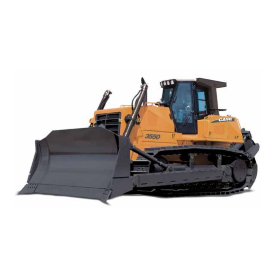
FOREWORD This manual is designed to serve as a guidance for correct and safe operation of the machine and its systematic servicing. The continued observance of the instructions provided herein will ensure best possible performance, operation economy and long life of the machine and will avoid the most common causes of accidents which may occur during work or maintenance operations. - Page 14 3550 3550 Crawler dozer D350M0001 The machine is shown with optional equipment. WARNING The safety of the operator and bystanders depends upon its judgement capacity and prudence in operating the machine. Thus it is necessary to be knowledgeable of the position and function of all controls.
-
Page 15: Identification Data
- manufacturer code (the first 3 digits) FNH; - the machine code 03550N; - the serial number (last 8 digits). MODEL MARKING ✩ FNH03550NBHC05001 ✩ 3550 Power Steering D350M0005 Carefully read personal and machine SAFETY PRECAUTIONS (at the beginning of this manual) -
Page 16: Quantitative Sides Of Comfort
3550 Machine manufactured by: CNH Italia S.p.A., Via Plava, 80 10135 Torino - Italy in the LECCE Plant Address: Zona Industriale Surbo 73100 LECCE (LE) Telephone: (0832) 6881 This machine complies with the EEC Directives relative to safety of machines (Directives 89/392,... -
Page 17: General Specifications
3550 GENERAL SPECIFICATIONS ENGINE Fuel system The fuel pump sucks the fuel from the tank. be- The engine complies with the regulations relative tween the tank and the fuel pump, the fuel flows to fume emissions "TIER2". through two interchangeable cartridge fuel filters, one a water separator, the other filtering the impu- rities in the fuel. - Page 18 3550 STEERING DIFFERENTIAL UNDERCARRIAGE The steering differential provides the steering of the Composed by two frames of a boxed and welded machine without stopping the track chain, transmitting structure type. The frames are connected frontally by continuously power to both track chains when steer- a swinging cross-member and are hinged at the rear on ing, also with tight turns.
- Page 19 3550 WEIGHT AND SPEEDS The weight of the machine with HSU bulldozer blade plus arms and lifting cylinders plus linkages, without ripper, safety cab, fluids and operator: 35,900 kg (79,150 lbs) Maximum speeds (forward-reverse) in km/h: Speeds - forward 10.3 - reverse 11.4...
-
Page 20: Main Dimensions
3550 MAIN DIMENSIONS 3375 3500 3243 2134 5282 2744 8234 (*) 610 mm shoes or 711 mm shoes D350M0006 Blade Blade Blade Tilt Pitch Digging Blade lifting BLADE TYPE width height capacity depth from ground Semi-U (HSU) 3975 1700 13°... -
Page 21: Stability
3550 STABILITY POSITION OF THE CENTRE OF GRAVITY WARNING In transportation condition The machine, as delivered by the plant, is not Note - the centre of gravity depends upon the position intended for any other application and, in particu- of the equipment. -
Page 22: List And Location Of Safety Decals
3550 LIST AND LOCATION OF SAFETY DECALS All the safety plates applied on the machine to provide maximum operational safety against unavoidable risks, are listed here below: They have been divided into four groups: Group A - danger decals Group B - warning decals... - Page 23 3550 LOCATION OF SAFETY DECALS 3550-M009 Carefully read personal and machine SAFETY PRECAUTIONS (at the beginning of this manual)
- Page 24 3550 "A" D350M0008 D350M0135 DETAIL A D350M0137 D350M0136 D350M0139 D350M0138 Carefully read personal and machine SAFETY PRECAUTIONS (at the beginning of this manual)
- Page 25 3550 LIST OF SAFETY DECALS Group A - Danger decals DANGER KEEP CLEAR W170-3M012 DANGER THE RETURN SPRING OF THE IDLER IS INSTALLED ON THE MA- CHINE WITH A CONSIDERABLE COMPRESSION LOAD. TO INSTALL AND REMOVE THIS PART COMPLY WITH THE PROCEDURES DE- SCRIBED IN THE "...
- Page 26 3550 LIST OF SAFETY DECALS Group B - Warning decals DANGER FLUID UNDER PRESSURE PRIOR TO REMOVING THE CAP OR THE COVER TURN IT SLOWLY TO RELEASE THE PRESSURE. REFER TO THE "OPERATION AND MAINTENANCE MANUAL". 79100862 S 76 D350M0043...
- Page 27 3550 WARNING WARNING ALWAYS TURN THE MASTER SWITCH TO THIS MACHINE IS EQUIPPED WITH A BLOCK POSITION BEFORE STARTING, POWER STEERING OPERATING ONLY OPERATING, MAINTAINING, FUELLING OR WHEN THE ENGINE IS IN OPERATION. SERVICING THE MACHINE AND AFTER PARKING IT.
- Page 28 3550 LIST OF SAFETY DECALS Group C - General purpose decals MACHINE MAINTENANCE AND LUBRICATION INSTRUCTIONS MAINTENACE INTERVAL HOURS OPERA- APPROX. DESIGNATION OF THE POINT OF INTERVENTION TYPE TIONS POINTS CAPACITY 250 500 1000 2000 ✓ ✗ ★ 35 L ENGINE: OIL LEVEL ✓...
- Page 29 3550 LIST OF SAFETY DECALS Group D - Manoeuvre decals D350M0142 D350M0143 WARNING BEFORE STARTING OR OPERATING THE MACHINE, READ THE "OPERATION AND MAINTENANCE" MANUAL. D350M0144 WARNING BEFORE LEAVING THE OPERA- D350M0146 TOR'S SEAT, PLACE THE LEVER IN LOCK POSITION...
- Page 30 3550 LIST OF SAFETY DECALS Group E - ROPS-FOPS homologation decals D350M0015 With cab D350M0016 With operation position only With operation position only D350M0017 With cab D350M0048 Carefully read personal and machine SAFETY PRECAUTIONS (at the beginning of this manual)
-
Page 31: Preliminary Instructions And Break-In Period
3550 PRELIMINARY INSTRUCTIONS AND BREAK-IN PERIOD PRELIMINARY INSTRUCTIONS BREAK-IN PERIOD When delivering the machine, the Sales Organisation A break-in period of at least 60 hours, is required, personnel provides the main instructions regarding its following the directions listed here below: operation and maintenance to the Customer. -
Page 32: Operation Rules
3550 OPERATION RULES WARNING Study carefully this Manual before starting, oper- Keep all persons away form equipment being ating, maintaining, fuelling or servicing the raised to avoid possible injuries. machine. Never attempt to operate the machine or its tools This alert symbol signals important mes- from any position other than seated in the opera- sages involving your safety. - Page 33 3550 Carefully read personal and machine SAFETY PRECAUTIONS (at the beginning of this manual)
-
Page 34: Controls And Instruments
3550 CONTROLS AND INSTRUMENTS Safety lever (equipment control and gearshifting 12. AUTO SHIFTING "AS" function button (Optional) lever locking) 13. Steering control levers Neutral button 14. Armrest adjustment levers Blade control lever 15. Transmission safety lever Ripper control lever (Gearshifting lock) Engine starter switch 16. - Page 35 3550 SAFETY LEVER (Equipment control BLADE CONTROL LEVER and gearshifting lever lock) The lever controls the raising, lowering and tilt of the The device, lifted as illustrated in the figure in position blade. A (vertically) blocks the EQUIPMENT CONTROL To raise or lower the blade, move the lever backward LEVERS AND THE GEARSHIFTING BUTTONS in into position D or forward into position H, respectively.
- Page 36 3550 RIPPER CONTROL LEVER (upon request) Safety lever - With lever forward in P = lowering the ripper. indicators - With lever backward in R = raising the ripper. - With lever forward + button = opening pitch. - With lever backward + button = closing pitch.
- Page 37 3550 Positions: ASHTRAY - Position allowing the insertion and removal of the starter key. Engine inoperative. 24V DC POWER OUTLET/ CIGARETTE LIGHTER - All functions related to electrical system services are activated. The indicator lights The power outlet is equipped with cigarette lighter (on...
- Page 38 3550 11. GEARSHIFTING GROUPE The machine is equipped with three forward and three reverse speeds. The controls are electrically actuated by the following buttons, located in the left side of the cab, on the ergonomic armrest. With the two safety levers lowered, when lever L is turned and pushed forward into position F the machine moves forward, selecting 1st gear.
- Page 39 3550 12. AUTOSHIFT "AS" FUNCTION 13. STEERING CONTROL LEVERS Button AS is selected when a work cycle must be performed with frequent FORWARD - REVERSE move- ments. The system is arranged in 1st forward for the work phase and 2nd reverse for the backward travel.
- Page 40 3550 Leftward steering To adjust the height and the angle, loosen lever A, adjust as required and lock it again. When pulling gradually the right lever, the rightward For the horizontal setting on the sliding guide, loosen steering occurs, the right track chain slows-down,...
- Page 41 3550 16. INSTRUMENT PANEL Indicator lights and instruments L10 L11 L12 n/min x 1000 1850-M0001 Battery charge indicator L10. Front work lights indicator Engine oil pressure indicator L11. Rear work lights indicator Engine air cleaner indicator L12. Headlights indicator + dashboard light Hydraulic oil filter indicator DL1.
- Page 42 Notice – In any case, keep in mind that in order to obtain maximum performance by the torque converter, the speed engaged must be appropriate for the work to be done.
- Page 43 3550 INSTRUMENTS Coolant temperature This instrument indicates the temperature of the cool- ant. When the temperature is too high (red zone), the indicator light (DL2, indicator lights figure) comes ON, signalling that the engine is overheating. Run engine with no load until temperature drops.
- Page 44 3550 When the failed component is one only, the display shows a code listed in TABLE 1. For each trouble code, find the corresponding compo- nent. Ex: 0 E016 TABLE 1 Failed component Trouble code Left proportional solenoid valve coil...
- Page 45 3550 17. SWITCH AND INDICATOR PANEL a b c 3550-M007 3550-M008 on CAB on ROPS a. FRONT/REAR 1 speed SWITCH (with cab only) - b. FRONT/REAR WASHER BUTTON (with cab only) - c. SIDE DOORS WASHER BUTTON - d. SIDE DOORS WIPER 2 speed SWITCH - e. LIGHT SWITCH - f. FRONT WORK LIGHT ACTIVATION SWITCH - g.
- Page 46 3550 18. ENGINE THROTTLE LEVER 20. ELECTRICAL SYSTEM MASTER SWITCH Forward = maximum acceleration. The electrical system master switch is found when Backward = minimum acceleration. opening the left panel, indicated in the figure. The key of the electrical system master switch must be in position ON when the system must be operational.
-
Page 47: Operating Instructions
DANGER Observe all start-up procedures and WARNINGS listed in this Manual. In case it is difficult to identify the cause of leak- age due to the presence of dirt, clean the compo- nent to be inspected. Start the engine to identify coolant or oil leakages. - Page 48 3550 Climb on the machine using only points where handrails and steps are provided. Prior to climbing on the machine, clean and inspect steps and handrails. Climb and descend the machine facing it. Kepp three contact points with handrails and steps.
-
Page 49: Stopping The Machine
3550 Do not keep the starter key in position START more Reduce the engine speed. than 10 seconds at each attempt; otherwise, the Move the gearshifting control to neutral, pressing starter motor is damaged. button N and engage the relevant safety lever into Warm-up the engine for at least 5 minutes, without neutral position A. -
Page 50: Stopping The Engine
Motion direction ON START ACC. Starter key D350M0021 Prior to leaving the machine, in case this is going to be unmanned, move the ELECTRICAL SYSTEM MASTER SWITCH into OFF and remove the key. 1850-M0134 1 - Height adjustment (mechanical). 2 - Operator's weight correct setting indicator. -
Page 51: Fuel Reservoir
3550 FUEL RESERVOIR BLADE ADJUSTMENT Angeldozer version The blade tilt and pitch can be obtained by the upper DANGER adjustment rod of the right or left link. Otherwise, when Extinguish all smoking materials and open flames he blade system is equipped with a hydraulic cylinder, before checking and filling fuel reservoirs. -
Page 52: Removal Of Cab
3550 CAB REMOVAL WARNING The removal of the cab is required to gain free access Make sure that the cables are anchored to a point to some main groups of the machine, needing repair strong enough to support the load to be applied. -
Page 53: Reinstallation Of Cab
3550 - Sling the cab protection structure using lifting chains - Remove the screws of the right and left front or cables in the point indicated in the figure and supports under the right and left front mudguard, as attach them to a hoist. -
Page 54: Brakes Disengagement
3550 BRAKES DISENGAGEMENT In the event the engine is inoperative and the machine must be moved, it is necessary to manually disengage the brakes, proceeding as follows: Tooling required: - wrench, 19 mm and 22 mm; - allen wrench 8 mm;... - Page 55 3550 Connect a hand pump (*75295017) to the brake port Tighten locknut (C fig. F) until it contacts the face of indicated in the figure and actuate it until the transmission housing to prevent piston (S) from disengagement screw (A, fig. E) protrudes, indicating returning in.
-
Page 56: Towing The Mechine
3550 TOWING THE MACHINE Prior to the towing, make sure that the cable or the towing bar are in good conditions and are strong enough for the towing. Use a cable or a towing bar having a capacity of at least 1.5 times the gross mass... -
Page 57: Moving The Machine With Outside Means
Cables and chains must be firmly secured; make sure that they are attached to a point strong enough in relation to the effort to be made, which, in any case, must not exceed the maximum allowed value for the D350M0168 towing hook involved. -
Page 58: Instructions For Lowering The Equipment To The Ground With Engine Inoperative
3550 INSTRUCTIONS LOWERING Loading EQUIPMENT TO THE GROUND WITH ENGINE Before proceeding with the loading operation, make INOPERATIVE sure the ramps and carrier platform are lined with suitable non-skid material (wood, rubber etc.) securely WARNING fixed to the above parts (avoid using wood planks, old Obey all procedures and WARNINGS relative to the tyres etc.). -
Page 59: Long Storage Of The Machine
WARNING The use of CASE is recommended. Please find in the Do not run the engine of this machine in closed table below the percentages of the mixture related to... -
Page 60: Starting The Machine At Low Temperatures
3550 STARTING THE MACHINE AT LOW TEMPERATURES The engine starts regularly with temperatures down to - 15 °C (5 °F), coolant at 50 % in the cooling system, engine oil SAE 10W-30 and fully efficient batteries. Temperature Activation of engine... -
Page 61: Machine Operation
3550 MACHINE OPERATION WARNING Never attempt to operate the machine or its Pay special attentions when working near over- equipment from any position other than seated in the hangs. operator's seat. In all circumstance, keep head, body, limbs, feet, hands and fingers within the operator's... - Page 62 3550 Blade pitch A. Loose soil. B. Hard soil. Dozing Road and ditch cutting When working on grades, it is best to move downhill for When cutting steep slopes (for roads or ditches) better traction. Gradually lower the blade at the dozing should begin by cutting the depth of the ditch beginning of each pass and accelerate the engine fully.
- Page 63 3550 Steering Grading The D350 Power Steering solves the steering After the ground has been dozed, the surface might be difficulties during the pushing phases of the materials, rough due to small windrows, ground lifted by the since it provides constant power to both track chains tracks or small piles left around turning points.
- Page 64 The same result can be obtained by manoeuvring in the forward or reverse action of the machine. reverse. In such a case, turn the machine so that the The choice of procedures used depends upon several side of the blade contacts the boulder, then disengage...
- Page 65 Sometimes, instead of piling it, the material is pushed walls which could fall on the machine, turn the blade to fill a ditch. In this case, since the filling material from time to time toward the wall and with it raised, tends to let the machine sink it is appropriate to build push the mound down.
- Page 66 3550 CENTRE SLOT DOZING OF PILE CUTTING A PILE WITH CENTRE SLOT D350M0069 D350M0171 Going over obstacles Hill work Any obstacle (logs, roots, ridges etc.) must be Dozing on side slopes requires special care. Even removed, if possible, or avoided. If this is impossible,...
- Page 67 In each case the best possible advantage should be taken with the soil configuration. When natural aids are not available, the machine can be moved onto boards or other lifts to start the cut at the desired slope.
- Page 68 3550 Clearing OPERATING TIPS In land clearing of brush and small trees, clearing can Before beginning to doze, the moldboard should have be accomplished in one pass, with the blade cutting proper tilt and pitch for the work to be done. While slightly below the ground.
- Page 69 When working on soft material, it is preferable to increase the depth rather than the speed. In the case of stratified materials, work crosswise and against the vein; on the contrary, if the material is landslipping. work in the direction of the landslide.
-
Page 70: Cab
3550 SAFETY CAB Do not climb or leave a machine while in motion. Do not jump off the machine. Safety cab with roll-over protection structure (ROPS) and against falling objects (FOPS) safegarding the Do not climb nor leave the machine while transporting operator. - Page 71 3550 To open the door form inside the cab, press the handle To open from inside, rotate the handle as indicated in button indicated in the figure. the figure. D350M0174 D350M0026 It is possible to keep the side doors open while the machine is operating.
- Page 72 3550 CAB LIGHTING CAB INSIDE HEATING AND VENTILATION The ceiling lights are located on the top of the cab. By turning knob A air taken from the outside or from Switch M in raised position activates fixed light L, in inside the cab (recirculation) is pushed into the cab.
- Page 73 3550 AIR CONDITIONER (optional) To replace the side and rear window blades, proceed as for the front wiper. The air conditioner is turned On by switch D. To adjust the cooling or heating inside the cab set lever B as described for the machine without air conditioner.
-
Page 74: Maintenance
3550 MAINTENANCE MAINTENANCE SAFETY WARNINGS Do not allow unauthorised personnel to perform Always place the starter switch in lock position any maintenance operation. Study carefully this prior to perform cleaning, repair or any other Manual before starting, operating, maintaining, intervention on the machine and after parking it, fuelling or servicing the machine. -
Page 75: Maintenance Operations
3550 MAINTENANCE OPERATIONS The service intervals indicated herein refer to normal Lubrication is an essential part of preventive operating conditions; during the initial break-in period maintenance, controlling to a great extent, the useful life and under particularly severe conditions, other intervals of the unit. -
Page 76: List Of On-Board Tools
3550 LIST OF ON-BOARD TOOLS - Double head wrench mm 24 + mm 27 - Double head wrench mm 19 + mm 22 - Double head wrench mm 13 + mm 17 - Double head wrench mm 12 + mm 14... -
Page 77: List Of Programmed Maintenance
3550 MAINTENANCE TABLE EVERY 10 HOURS WORK (DAILY) EVERY 1000 HOURS WORK 1 Engine oil: check oil level 21 Fuel filters: replace filters 2 Torque converter/transmission hydraulic 22 Bevel gear set/brakes: change oil and suction circuit: check oil level filter... -
Page 78: Every 10 Hors Work
3550 EVERY 10 HOURS WORK TORQUE CONVERTER/TRANSMISSION HY- DRAULIC CIRCUIT - Check oil level ENGINE: Open the right upper panel. With the engine inoperative since at least 15 minutes and the machine on flat ENGINE OIL: Check oil level ground, check that the oil level is near the upper mark etched on dipstick 1 attached to the cap. -
Page 79: Every 50 Hours Work
3550 EVERY 50 HOURS WORK FUEL TANK - Draining condensation EQUIPMENT HYDRAULIC SYSTEM - Drain the impurities (water and deposits) from the Oil level check bottom of the tank collected by the draining well, from the lower side of the machine. - Page 80 3550 EVERY 50 HOURS WORK BLADE LINKAGE CYLINDERS - Greasing the linkages Pump grease into the grease fittings for the lubrication of the blade articulations. The grease fittings indicated by arrows are located on the opposite side of the machine, as well.
-
Page 81: Every 250 Hours Work
3550 EVERY 50 HOURS WORK 11. ENGINE OIL - Changing the oil Open the left front panel of the engine compartment BEVEL GEAR SET / BRAKES - Check oil level and drain, with hot engine, the oil through lower plug T, removed using a 8 mm Allen wrench. - Page 82 Open the right and left panels of the engine and make a visual inspection. In case of cross-way cracks on the belt are acceptable. Cross-way cracks combined with longitudinal cracks, flak- ing and breaks are not acceptable.
- Page 83 A more accurate check can be done using a belt dynamometer applied in the same middle position of the longest side of the belt. The tension limits, in this case, should be included between a minimum of 36 daN and a maximum 49 daN.
-
Page 84: Every 500 Hours Work
3550 17. BEVEL GEAR SET/BRAKES RETURN FILTER - EVERY 500 HOURS WORK Replacing the filtering cartridge 16. ENGINE OIL FILTER - Open the left panel of the engine compartment and Replacing the filtering cartridge remove filter F1 from the relevant support. Replace it with a new one and tighten it to 3.5 - 4 daNm. - Page 85 3550 EVERY 500 HOURS WORK 20. ENGINE COOLANT FILTER - Replacing the filtering cartridge 19. RETURN FILTER ON THE EQUIPMENT Open the upper panel of the engine compartment. HYDRAULIC CIRCUIT - Replacing the filtering cartridge DANGER Proceed as follows: Fluid under pressure. Prior to removing the cap, - clean cover L of the filter and the surrounding area;...
-
Page 86: Every 1000 Hours Work
3550 EVERY 500 HOURS WORK D350M0112 D350M0111 Remove filter F preventing any spill of liquid. Prior to reinstalling a new filter, clean the gasket contact area on the support. Install the new filter after smearing a thin film of oil on the gasket, until it touches the seat on the support. - Page 87 3550 EVERY 1000 HOURS WORK WARNING Replace the suction filter. Remove the filter indicated Do not run the engine of this machine in closed in the figure and replace it with a new one. Check the areas without proper ventilation to remove deadly level and top-up as required.
- Page 88 3550 EVERY 1000 HOURS WORK 25. BATTERIES - Checking the electrolyte level Refilling of oil WARNING Retighten the plug, after cleaning it accurately, and fill with oil through filler neck 1 up to the upper mark Batteries contain SULPHURIC ACID.
- Page 89 3550 EVERY 1000 HOURS WORK 27. ENGINE AIR CLEANER - Replacing the cartridges 26. FINAL DRIVES - Changing the oil Open the left panel of the engine compartment. Remove the cover from canister C freeing hooks D. - Stop the machine with plugs P indicated in the figure Extract the two co-axial filtering elements.
- Page 90 3550 29. TRANSMISSION/TORQUE CONVERTER EVERY 1000 HOURS WORK BREATHER - Replacement 28. TRANSMISSION/TORQUE CONVERTER Open the left panel of the engine compartment to reach SUCTION FILTER - Cleaning the filter breather A indicated in the figure. With the machine on flat ground and hot transmission oil, remove the draining plug indicated in the figure.
- Page 91 3550 31-32. FUEL INJECTORS-ENGINE VALVES - EVERY 1000 HOURS WORK Check calibration of injectors 30. BEVEL GEAR SET AND BRAKES BREATHER - Replace DANGER Open the right rear panel to reach breather B indicated Keep hands away from the tip of injectors when in the figure.
-
Page 92: Every 2000 Hours Work
3550 EVERY 2000 HOURS WORK 34. EQUIPMENT HYDRAULIC CIRCUIT - Oil change Draining the oil - Place the machine on flat ground, with the equip- ment resting on the ground; - remove oil filler cap D and remove lower plug T to drain the oil form the tank. -
Page 93: When Required
3550 37. FUEL FILTERS - AS REQUIRED Draining the condensation Operations to be performed when the relevant indica- Operation to be performed when the blue indicator tors are activated: on the monitor panel comes ON, indicating the requirement for the draining of water from the fuel 1. -
Page 94: Operations To Be Performed, When Required
3550 To reach the compartment, loosen screws V and lift OTHER OPERATIONS TO BE cover C. PERFORMED AS REQUIRED 38. UNDERCARRIAGE - Checking the sag of the track chains WARNING Fluid under pressure. To educe the tension of the track chains, please comply with the procedure suggested in the "Operation and Maintenance... -
Page 95: Electrical System
3550 ELECTRICAL SYSTEM FUSES The fuses are visible on the left side of the dashboard for the version with cab and inside the front pocket (as indicated in the figure). Remove the covers press fitted on fuse boxes A and... -
Page 96: Electrical Diagram Of Protection Tree
3550 Carefully read personal and machine SAFETY PRECAUTIONS (at the beginning of this manual) -
Page 97: Table Of Fluid Capacities
3550 Carefully read personal and machine SAFETY PRECAUTIONS (at the beginning of this manual) - Page 98 COPYRIGHT BY CNH Italia S.p.A. Product Support Via Plava, 80 - 10135 Torino All rights reserved. Reproduction of text and illustrations in whole or in part, is strictly prohibited Print No. 84415679 - English - II - 2011...
Need help?
Do you have a question about the 3550 and is the answer not in the manual?
Questions and answers