Advertisement
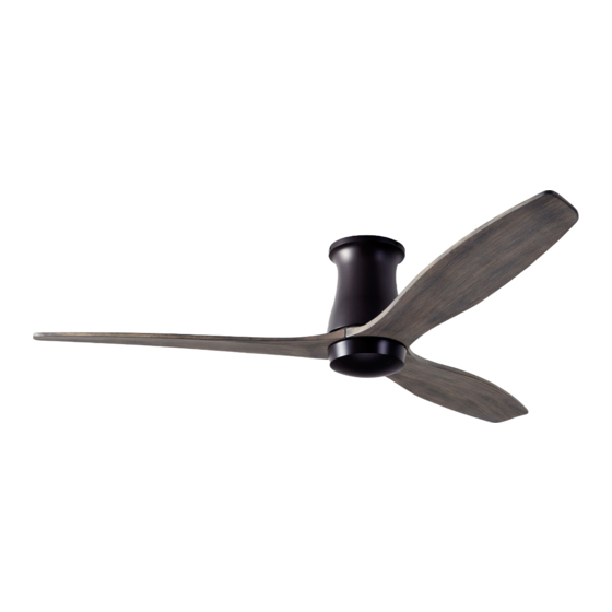
Arbor Flush DC
Fan Installation ..........................................4
Control Installation and Wiring ..........7
Troubleshooting ...................................... 12
Maintenance ............................................ 14
Warranty ...................................................... 15
Installation Instructions
and Owners Manual
Models: ARB-FM-XX-XX-XX-XX(X)-XX
Net Weight of Fan: 13.0 lbs (5.9 kgs)
Please read and save
these instructions.
If you have any
questions while
installing your fan,
call us first!
Customer Service
Monday-Friday, 8am-4pm
tel 888-588-3267
V2020/08
(PST)
Advertisement

Subscribe to Our Youtube Channel
Related Manuals for The Modern Fan Company Arbor Flush DC


Summary of Contents for The Modern Fan Company Arbor Flush DC
-
Page 1: Table Of Contents
Arbor Flush DC Installation Instructions and Owners Manual Models: ARB-FM–XX–XX–XX–XX(X)–XX Net Weight of Fan: 13.0 lbs (5.9 kgs) V2020/08 Please read and save these instructions. If you have any questions while installing your fan, call us first! Customer Service Monday–Friday, 8am–4pm... -
Page 2: Safety Instructions And Warnings
Safety Instructions and Warnings Please read all safety instructions prior to installing your ceiling fan and save this document for future reference. If you are in doubt with any of the information provided, we recommend that you consult or hire a qualified electrician to install your outlet box and ceiling fan. If you have any questions or difficulty installing your fan, call Modern Fan Co customer service at (888) 588-3267. - Page 3 Installation Preparation WARNING Fan Location Make sure the installation site you choose allows the fan blades to rotate without any obstruction. Allow a minimum clearance of 7 feet (2.1 meters) from the floor to the blades and 30 inches Minimum of (76 cm) from the wall to the 7 feet (2.1m) end of the blades.
-
Page 4: Fan Installation
Fan Installation Tools Needed A stepladder, Phillips head screwdriver and a Instructions wire stripper IMPORTANT: The included canopy receiver must be installed and paired with the wall or remote control components (see page 10). Third party fan controls may not be used with this product. Connecting this fan to line voltage without the canopy receiver will damage the motor and void your warranty. - Page 5 See Page 2-3 Circuit Breaker WARNING POWER OFF Using the existing screws provided with your junction box, secure the mounting plate to the ceiling junction box. Junction box must be visibly marked as “Acceptable for Fan Support. ” It is recommended that the flat washers and lock washers from the hardware pack be used for added security.
- Page 6 Fan Installation Circuit Breaker See Pages 2-3 (continued) WARNING POWER OFF Identify control components from control package/s (see Step 1). In addition to a receiving unit, your fan may have been ordered with a wall control (transmitter), a handheld remote control (transmitter) or both. Wiring Diagram blue for optional light white...
-
Page 7: Control Installation And Wiring
WARNING!! Power must be disconnected at circuit breaker prior to any contact with electrical wires. Once wire connections are completed, lift fan body and carefully align collar with ceiling plate. Tabs on ceiling plate should seat into channel on inside of fan collar. - Page 8 Fan Installation Circuit Breaker See Pages 2-3 (continued) WARNING POWER OFF Insert a blade screw and washer from the hardware pack through the center blade hole and position under the motor so that the screw is aligned with the “center” hole position of any group of three screw holes.
- Page 9 WARNING!! Power must be disconnected at circuit breaker prior to any contact with electrical wires. If your fan was ordered with the optional LED light, begin by identifying all parts (see Step 1), then follow steps (a) through (d). (a) Remove bottom hub plate held by three screws shown here.
- Page 10 Fan Installation Circuit Breaker See Pages 2-3 (continued) WARNING POWER OFF Control Pairing Wall controls and remote handsets communicate with the canopy receiver using radio frequency transmission. Each device (wall control and remote handset) is factory set to a unique channel to avoid unwanted interference with other fans installed nearby.
- Page 11 Fan and Light Operation This fan operates with a micro-controller (enclosed in the canopy receiver) which regulates fan speed, fan direction and light function. After sending any operational command to your fan, wait several seconds before re-sending the same command or sending a new command.
-
Page 12: Troubleshooting
Troubleshooting Please read all installation instructions carefully. After reviewing the following troubleshooting tips, if you are unable to solve a problem with the installation or operation of you fan, please contact customer service for additional assistance. I M P ORTANT: Do not return a fan or fan parts without first contacting us for troubleshooting assistance. - Page 13 Fan wobbles... • Make sure hanging bracket and mounting hardware at ceiling is secure and firmly fastened. • Be sure ridge in hanging bracket is seated in the half-ball slot. • Check that stopper screw (or stopper pin) and set screws are firmly tightened where down rod is attached to the fan body.
-
Page 14: Maintenance
Maintenance See Pages 2-3 Circuit Breaker WARNING POWER OFF Before servicing or cleaning your fan, switch power off at service panel and lock the service disconnecting means to prevent power from being switched on accidentally. When the service disconnecting means cannot be locked, securely fasten a prominent warning device, such a tag, to the service panel. -
Page 15: Warranty
Lifetime Limited Warranty All products manufactured and sold by The Modern Fan Co. meet the highest industry standards. We use only the finest materials and production processes resulting in quality ceiling fans backed by the following warranty: Motors (dry locations): .......................Lifetime Motors (damp locations): .................... - Page 16 The Modern Fan Company, Inc. 709 Washington Street, Ashland, Oregon 97520 tel 888-588-3267, fax 541-482-8418 info@modernfan.com modernfan.com V2020/08...
Need help?
Do you have a question about the Arbor Flush DC and is the answer not in the manual?
Questions and answers