
Related Manuals for socomec ATyS A15


Summary of Contents for socomec ATyS A15
- Page 1 INSTRUCTION MANUAL ATyS A15 ATS Controller www.socomec.com To download, brochures, catalogues and technical manuals:...
-
Page 2: Table Of Contents
......... . .12 6.4. ATYS A15 ACCESSORIES AND COMPATIBLE PRODUCTS . - Page 3 ............36 ATyS Controller A15 - 549779A - SOCOMEC...
-
Page 4: General Safety Instructions
• This manual provides instructions on safety, connections instructions on the SOCOMEC ATyS A15 ATS controller • Weather the ATyS A15 is sold as a loose product, as a spare, in a kit or as part of an enclosed solution or in any other... -
Page 5: Standards
2. STANDARDS • As a minimum the ATyS A15 comply with the following international standards: o IEC/EN 60947-6-1* o IEC/EN 60947-1 o IEC/EN 61010-2-201 o IEC/EN 61010-2-030 o IEC/EN 61010-1 o GB/T 14048.11* o GB/T 14048.11 Annex C o EMC 60947 •... -
Page 6: Introduction
IEC 60947-6-1, GB 14048-11 and other international standards as listed. As a standalone product the ATyS A15 is compliant with IEC 61010-2-201 and is compatible with use with PC and CC type RTSE. ATyS A15 “ATS Controller” Ensures: •... -
Page 7: The Atys Family Product Range
ATyS will be installed. This instruction manual includes details and instructions specific to the “ATyS A15” ATS controller only. For all other ATyS family of products please refer to the specific instruction manual related to that product. -
Page 8: Quick Start
5. QUICK START (0/+0,8) 301 302 ATyS Controller A15 - 549779A - SOCOMEC... -
Page 9: General Overview
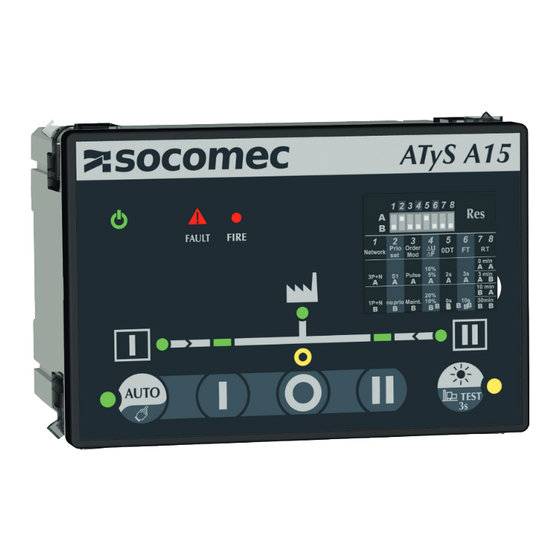
6. GENERAL OVERVIEW 6.1. Product identification 1. AUTO/Manual selector 2. Controller state LED 3. Remote position order selector 4. ATSE Synoptic 5. Test function selector 6. DIP switch programing ATyS Controller A15 - 549779A - SOCOMEC... -
Page 10: Controller Hmi
11. Fault LED (Red blinking – long blink when fault or product in inhibited, fast blink when a dip switch parameter has been changed and needs validation). 12. Fire (Red when fire input is activated). See Annex I page 29 for more details on the LED indicators ATyS Controller A15 - 549779A - SOCOMEC... -
Page 11: Environmental
• Volume LxWxH (mm): 172x128x154.5 • Weight : 850 g 6.3.8. Lead free process • The ATyS A15 complies with : • The UE directive for RoHS 2 2011/65/UE • The UE directive RoHS 3 2015/863/UE • China RoHS 2 SJ/T 11364-2014... -
Page 12: Weee
6.3.11. Other compliances and marking 6.4. ATyS A15 ACCESSORIES AND COMPATIBLE PRODUCTS The ATyS A15 is compatible and compliant according to IEC 60947-6-1 when used with the following IEC 60947-6-1 SOCOMEC RTSE and specific product connection harness • ATyS S (from 40-125A) •... -
Page 13: Installation
Door cut-out of 93(+0.8) x138(+1) mm, door thickness 1.5- 3mm. Remove all connectors and clip before inserting the controller in the cut-out then fix the controller in place using all 4 fixations clips (cf. image below): ATyS Controller A15 - 549779A - SOCOMEC... -
Page 14: Din Rail Mounting
Install on IEC 60715 Standard Din RAIL. When mounting make sure both clips are pushed up, then clip on the DIN Rail. To remove from the DIN Rail, drag the two mounting clips down before removing the product. ATyS Controller A15 - 549779A - SOCOMEC... -
Page 15: Connections
9. CONNECTIONS When using the ATyS A15 without the Socomec Harness, gG 4A fuse protection is DANGER required on the voltage sensing inputs cf connection diagrams. When using the A15 with ATyS R and the Socomec harness gG fuses are mandatory. -
Page 16: Metering And Sensing Detail
In 3 phases with Neutral balanced networks, there is a risk that the loss of neutral will not be detected. CAUTION To limit this risk the Dip switch 4 (Hysteresis) can be switched to position A. (Cf chapter 10-5 programing). ATyS Controller A15 - 549779A - SOCOMEC... -
Page 17: Connections
3. Enable control when closed / disable control when open 4. Not used 5. Genset Start relay 6. RTSE position control outputs 7. Source 1 and 2 voltage inputs 8. 24 V.d.c Aux supply 9. External DPS – Input / output ATyS Controller A15 - 549779A - SOCOMEC... -
Page 18: Connection Diagrams With Atys R
104 105 106 203 204 205 206 Aux supply S1 IN S2 IN 102 101 302 301 202 201 14 15 16 17 DPS OUT *Using a Socomec cable harness kit excludes the need for fuses ATyS Controller A15 - 549779A - SOCOMEC... -
Page 19: Terminal Denomination, Description And Characteristics
NOTE 1: Use 7mm as stripping length for the controller terminals NOTE 2: Use 90°C copper wire for installations with ambient temperature from 35-60°C. When the ambient temperature is above 60°C, Use 105°C copper wire. ATyS Controller A15 - 549779A - SOCOMEC... -
Page 20: Atys A15 Operating Modes
10. ATYS A15 OPERATING MODES The ATyS A15 has 3 distinct working modes, the working modes are selected using the HMI button or by using the 63A/64A input. The 3 working modes are working as described below: • Auto mode In this mode the controller will automatically give orders to the RTSE connected to switch to the correct position according to the settings selected. -
Page 21: Triple Power Supply
• Frequency within set limits The ATyS A15 will check that the frequency is within the limits configured through DIP switch 4. Frequency is checked on L1 only. • Loss of the main or alternate power supply Loss of supply depends on the nominal voltage and frequency configured together with the hysteresis (set in DIP switch 4)The source will be considered as lost after the fail timer as counted down (set through dip switches 7 &... -
Page 22: Fixed Outputs
Control signal outputs are the output orders (dry contact) to the RTSE; the ATyS A15 includes 3 signal outputs and a common (point powered by the user) (Terminals 17 to 14). These outputs are rated for 250 Vac, 50/60 Hz 5A general use , and 30 V.d.c 5A general use. -
Page 23: Fixed Inputs
0 and both manual and automatic controls will be inhibited. When the input is removed, the switch will go back to the last working mode automatically ATyS Controller A15 - 549779A - SOCOMEC... -
Page 24: Programming
Wait time of 30min before source is lost returns ( retrun timer = 30min) *When 0min is selected the return timer is set to 3s **When Control mode contactor is selected the minimum hysteresis is -15% ATyS Controller A15 - 549779A - SOCOMEC... -
Page 25: Characteristics
Good engineering practice is imperative whilst all necessary precautions must be taken to ensure that the intervention (whether directly or indirectly) remains safe in all aspects. ATyS Controller A15 - 549779A - SOCOMEC... -
Page 26: Trouble Shooting Guide
- Check if the alarm LED is blinking. taken into account - Verify that you are in manual mode when changing DIP switch parameters. - Press the “RES” button for less than 3s to validate the parameter change. ATyS Controller A15 - 549779A - SOCOMEC... -
Page 27: Associated Products
9594 9012 24/48 VDC 9506 4010 100 A 12 VDC 9505 4010 230 VAC 9503 4010 9599 4001 9506 4012 24/48 VDC 125 A 12 VDC 9505 4012 230 VAC 9503 4012 9599 4001 ATyS Controller A15 - 549779A - SOCOMEC... - Page 28 To shroud front switch top and bottom 2 references required (Whenever a bridging beam is fitted, it is then only possible to fit 3 times the reference for the terminal cover). (3) Factory mounting only. ATyS Controller A15 - 549779A - SOCOMEC...
-
Page 29: Annexe I
11. Fault LED (Red blinking – long blink when fault or product in inhibited, fast blink when a dip switch parameter has been changed and needs validation). 12. Fire (Red when fire input is activated). ATyS Controller A15 - 549779A - SOCOMEC... -
Page 30: Led Functioning Modes
Long blinking (2Hz): Inhibit input is active or fault is active *Considering that the controller is powered. **Considering that lamp TEST has not been initiated ATyS Controller A15 - 549779A - SOCOMEC... -
Page 31: Connection Diagrams
104 105 106 203 204 205 206 Aux supply S1 IN S2 IN 102 101 302 301 202 201 14 15 16 17 DPS OUT *Using a Socomec cable harness kit excludes the need for fuses ATyS Controller A15 - 549779A - SOCOMEC... -
Page 32: Connections With Atys Dm
104 105 106 203 204 205 206 Aux supply S1 IN S2 IN 102 101 302 301 202 201 14 15 16 17 DPS OUT *Using a Socomec cable harness kit excludes the need for fuses ATyS Controller A15 - 549779A - SOCOMEC... -
Page 33: Connections With Standard Cc Type Based Tse
104 105 106 203 204 205 206 Aux supply S1 IN S2 IN 102 101 302 301 202 201 14 15 16 17 DPS OUT *Using a Socomec cable harness kit excludes the need for fuses ATyS Controller A15 - 549779A - SOCOMEC... -
Page 34: Phase Rotation Check
If only one source is present, the controller will give the order to switch to this source before the return timer has finished counting. + U/ F [Hyst] Vn 230 V a c L/N Un 400 V a c L/L Fn 50Hz [Hyst] - U/ F Start FT Start RT Start FT Start RT Source available ATyS Controller A15 - 549779A - SOCOMEC... -
Page 35: Cooldown Timer
The product will remain on source 2 until the test ends, to end the test press again the test button for more than 3s to return in the last working mode (Manual or Automatic). It is also possible to start and stop the test on load and off load through communication ATyS Controller A15 - 549779A - SOCOMEC... -
Page 36: A15 Operating Sequence
15.8. A15 Operating sequence Controller operating sequence with source 1 priority: DPS Output operating sequence : ATyS Controller A15 - 549779A - SOCOMEC... - Page 37 ATyS Controller A15 - 549779A - SOCOMEC...
- Page 38 CORPORATE HQ CONTACT: SOCOMEC SAS 1-4 RUE DE WESTHOUSE 67235 BENFELD, FRANCE www.socomec.com 549779A...
Need help?
Do you have a question about the ATyS A15 and is the answer not in the manual?
Questions and answers