
Related Manuals for socomec ATyS C40


Summary of Contents for socomec ATyS C40
- Page 1 CONTROLLER ATyS C40 Notice d’utilisation - Operating instructions MAKE YOUR BUSINESS SAFE SOCOMEC GROUP SWITCHING PROTECTION & UPS...
-
Page 2: Table Of Contents
Product introduction ____________________________36 INSTALLATION __________________________________37 Mounting _____________________________________37 Dimensions ___________________________________37 Characteristics_________________________________37 CONNECTIONS _________________________________38 Control circuits_________________________________38 OPERATION ____________________________________42 Presentation ___________________________________42 Operational modes _____________________________43 Programming __________________________________44 Operation _____________________________________56 Visualisation ___________________________________60 Automatic sequences ___________________________62 TROUBLESHOOTING GUIDE _____________________64 SOCOMEC - Réf. : 532 929 B... -
Page 3: The Atys Range
• ATyS 3e, 6e • ATyS 6m • Remote interfaces ATyS D10 & D20 • ATyS C20 / C30 controller For personnel and product safety, please read the contents of these operating instructions carefully before connecting. SOCOMEC - Réf. : 532 929 B... -
Page 4: General Presentation
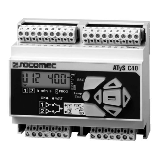
ATyS Controller GENERAL PRESENTATION ATyS C40 Product introduction > ATyS C40 Control terminals Modular frame Voltage sensing and power supply terminals Keypad SOCOMEC - Réf. : 532 929 B... -
Page 5: Installation
> Operation • Temperature : -20 °C to +60 °C • Humidity : 80 % at 55 °C 95 % at 40 °C > Consumption 7.5 VA max > Measurement category Cat III SOCOMEC - Réf. : 532 929 B... -
Page 6: Connections
Control 13 14 23 24 33 34 43 44 53 301 302 303 304 305 306 DC- DC+ Maximum control cables lenght = 10 m. In case of longer distance, insert control relays. SOCOMEC - Réf. : 532 929 B... - Page 7 230 Vac 5 A 13 14 23 24 33 34 43 44 53 301 302 303 304 305 306 DC- DC+ Maximum control cables lenght = 10 m. In case of longer distance, insert control relays. SOCOMEC - Réf. : 532 929 B...
- Page 8 13 14 23 24 33 34 43 44 53 301 302 303 304 305 306 DC- DC+ * Only on DC versions. Maximum control cables lenght = 10 m. In case of longer distance, insert control relays. SOCOMEC - Réf. : 532 929 B...
- Page 9 Programmable input 2 any power supply Common Specifique voltage supply Do not connect to 1.5 mm input Common terminals 301 to 310 any power supply (1) Refer to programming, Setup, to modify relay state. SOCOMEC - Réf. : 532 929 B...
-
Page 10: Operation
Operational modes - Active source: to force the next active source 2 green leds: - switch I state - Partial counter reset - Genset remote start (test of load) - switch II state SOCOMEC - Réf. : 532 929 B... -
Page 11: Operational Modes
(3 minutes power off action to allow reset). Version number Operational modes VISUALISATION OPERATION Measured values & parametered timers display. Always Test sequences. Password access (code 4000). accessible without code. PROGRAMMING Parameters configuration. Password access (code 1000 from factory). SOCOMEC - Réf. : 532 929 B... -
Page 12: Programming
• Press and hold for 5 s “validation” push button “validation” push button • Step 2: enter code (factory code = 1000) using navigation push buttons • Step 3: press validation push button SOCOMEC - Réf. : 532 929 B... - Page 13 Controller ATyS OPERATION Programming PROGRAMMING MENU ARCHITECTURE SOCOMEC - Réf. : 532 929 B...
- Page 14 400 to 230 V. Press to access first digit (blinking) Press 2X to display 2 (blinking) Press to access second digit (blinking) Press 3X to display 3 (blinking) Press to validate SOCOMEC - Réf. : 532 929 B...
- Page 15 YES or nO permutation counter Reset Programming Programming code modification From 0000 to 1000 code 9999 Restricted Restricted access (counters rS1 and rS2) code modification From 0000 to 5000 access code 9999 modification SOCOMEC - Réf. : 532 929 B...
- Page 16 YES global working time counter for source 1 Reset of the Reset of the global working time counter for source 2 nO or YES global working time counter for source 2 SOCOMEC - Réf. : 532 929 B...
- Page 17 85 % to 98 % Network 2 under voltage threshold hysteresis From 81 95 % to 99 % (> uU) Values definition: % of nominal values Hysteresis values range is limited by thresholds values. SOCOMEC - Réf. : 532 929 B...
- Page 18 95 % to 99 % Network 2 under frequency threshold hysteresis From 80.5 97 % to 99.5 % (> uF) Values definition: % of nominal values Hysteresis values range is limited by thresholds values. SOCOMEC - Réf. : 532 929 B...
- Page 19 2 to source 1 source 1 Cool down Allows generator cooling down period after load’s retransfer From 0 to 4 mn timer source 2 from source 2 -> source 1 30 mn SOCOMEC - Réf. : 532 929 B...
- Page 20 Input 3 SSt, Ft1, AL1, Ft2, AL2, MAn, MtF, / Input 3 state nO or nC Output* S1A, S2A, ScA, / * Non available in IMP logic (see LOG in SETUP menu). SOCOMEC - Réf. : 532 929 B...
- Page 21 Output activated as soon as source 1 or Source 2 considered available (similar to one of front led source 1or Source 2). * Non available in IMP logic (see LOG in SETUP menu). SOCOMEC - Réf. : 532 929 B...
- Page 22 OSF 1 -> 2 Position G1 Position O Position G2 tG 1 = 0.5xtF1 + 1xtF1 + the old tG 1 tG 2 = 1xtF2 + x + 0.5xtF1 + the old tG 2 SOCOMEC - Réf. : 532 929 B...
- Page 23 OSF 1 -> 2 Position G1 Position O Position G2 tG 1 = 0.5xtF1 + 1xtF1 + the old tG 1 tG 2 = 1xtF2 + x + 0.5xtF1 + the old tG 2 SOCOMEC - Réf. : 532 929 B...
-
Page 24: Operation
(code 4000) Navigate in operation mode: • Step 3: press “validation” • Press “TEST” push button to access push button different features • Press “validation” push button to activate required function SOCOMEC - Réf. : 532 929 B... - Page 25 No, press Yes, press “validation” “validation” “validation” Test off Load source 2 Source 2 available ? Stop source 2 ? Yes, press No, press Yes, press “validation” “validation” “validation” Exit: press 5 seconds SOCOMEC - Réf. : 532 929 B...
- Page 26 “source” menu in the programming mode. reseted. This timer can be reset punctually during a running of - If the LCD indicate “rES YES”, then the timer is reseted. the associated genset. SOCOMEC - Réf. : 532 929 B...
- Page 27 • The test is not possible during an automatic sequence > Keypad activation Gen? After operation mode access, press mode push button to make a test with the load led blinking and validate to start the sequence. Validate Stop Gen? Gen stopped SOCOMEC - Réf. : 532 929 B...
-
Page 28: Visualisation
LCD displays voltage available on active network. Navigation in visualisation mode: • Press “up” and “bottom” push buttons to access required parameter • Press “left” and “right” push buttons to navigate in the different menus SOCOMEC - Réf. : 532 929 B... - Page 29 Controller ATyS OPERATION Visualisation VISUALISATION ARCHITECTURE MODE SOCOMEC - Réf. : 532 929 B...
-
Page 30: Automatic Sequences
OSF 1 -> 2 OSF 2 -> 1 OSF 1 -> 2 Position G1 Position O Position G2 tG 1 = 2xtF1 + the old tG 1 tG 2 = 1,5xtF2 + the old tG 2 SOCOMEC - Réf. : 532 929 B... - Page 31 2 = 1xtF2 + x + 0.5xtF1 + the old tG 2 NB: in case of source 1 reappearance, it might be prefe- rable not to retransfer immediately the load. Manual retransfer feature can be activated if required from keypad or remotely (cf. programming). SOCOMEC - Réf. : 532 929 B...
-
Page 32: Troubleshooting Guide
• Verify the number of AC in the setup menu. It must be in conformity with the number of AC connected • Verify the switch position Error LCD Err XXXX • Send the product back to the manufacturer SOCOMEC - Réf. : 532 929 B...
Need help?
Do you have a question about the ATyS C40 and is the answer not in the manual?
Questions and answers