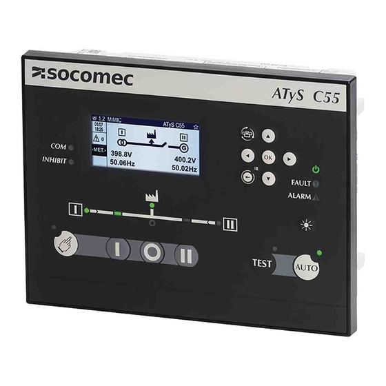
socomec ATyS C55 Quick Start
Ats controller
Hide thumbs
Also See for ATyS C55:
- Installation and operating manual (110 pages) ,
- Installation and operating manual (124 pages)
Table of Contents
Advertisement
Quick Links
STEP 4
Visualization
1
MIMIC
2
STATUS
<1.1>
STATUS
<2.1>
STATUS
<1.2>
METERING
<2.2>
SYNCHRONIZATION
<1.3>
INFORMATION
- Short press on this button to cycle the dashboards starting by the dashboard set as favorite.
- Long press to select current dashboard as favorite.
7
INPUTS OUPUTS
<7.1>
INPUTS
<6.1>
<7.2>
OUPUTS
<6.2>
*
<7.3>
EXTERNAL INPUTS
*
<7.4>
EXTERNAL OUPUTS
*
C65 only
STEP 5
Menus & programming
- Short press on this button to go back one level.
MAIN MENU
- Long press to access the menus.
CONTROL
LOG
GENSET SCHEDULER
PARAMETERS
SPECIFIC FUNCTIONS
CONTROL
MODE/POSITION
TEST
*
MANUAL RETRANSFER
LOG
EVENT LOG
*
EVENT BY DATE
ALARM LOG
FAULTS
STATISTICS
SCHEDULER
GENERAL PARAMETERS
CUSTOM 1
*
CUSTOM 2
*
CUSTOM 3
*
CUSTOM 4
PARAMETERS
NETWORK
*
LOAD
DISPLAY
TIMERS
I/0
COMMUNICATION
ALARMS
PASSWORD
WIZARD
SPECIFIC FUNCTIONS
MANUAL RETRANSFER
*
INPHASE TRANSFER
*
RETURN TO 0
*
LIFT CONTROL
*
FORCED LOAD SHEDDING
*
SMART LOAD SHEDDING
POWER UP IN AUTO
*
DBT TIMER IN CTRL
HVAC COMPRESSOR
3
METERING
4
POWER & ENERGY
<3.1>
SYSTEM
<4.1>
SYSTEM
*
<3.2>
I : CURRENT
<4.2>
P : ACTIVE POWER
<3.3>
V : P-N VOLTAGE
<4.3>
Q : REACTIVE POWER
<3.4>
U: P-P VOLTAGE
<4.4>
S : APPARENT POWER
<3.5>
FREQUENCY
<4.5>
PF : POWER FACTOR
<4.6>
Ea : ACTIVE ENERGY
<4.7>
Er : REACTIVE ENERGY
<4.8>
Es : APPARENT ENERGY
<4.9>
RESET ENERGY
6
ALARMS
5
TIMERS
ACTIVE ALARMS
<5.1>
RUNNING TIMERS
FINISHED ALARMS
<5.2>
SOURCE 1 TIMERS
<5.3>
SOURCE 2 TIMERS
<5.4>
OPTIONAL TIMERS
<5.5>
TEST ORDER TIMERS
<5.6>
EXTERNAL TEST TIMERS
NETWORK
I/O
AUTODETECT
INPUTS
SETUP
OUTPUTS
APPLICATION
EXTERNAL I/O DETECTION
OP RANGE S1
EXTERNAL I/O CONFIG
OP RANGE S2
LOAD
COMMUNICATIONS
LOAD STATUS
MODBUS ADDRESS
LOAD TYPE
RS485 MODBUS
INOM
DIGIBUS COMM
LOAD NAME
DIGIWARE MODE
CT PRIMARY
CT SECONDARY
NEUTRAL CT PRIMARY
NEUTRAL CT SECONDARY
LINE I1 WAY
LINE I2 WAY
LINE I3 WAY
LINE I4 WAY
DISPLAY
ALARMS
SCREEN
MEASURE ALARMS CONFIG
DATE AND TIME
MAINTENANCE ALARMS CONFIG
*
LED CONFIG
COMBINATION ALARMS CONFIG
OPTIONS
LOGICAL ALARMS CONFIG
CHANGE PRODUCT NAME
SYSTEM ALARMS CONFIG
TIMERS
PASSWORDS
OPERATION
CHANGE OPERATOR PWD
GENSET SOURCE 1
CHANGE CONFIG PWD
GENSET SOURCE 2
CHANGE MAINTENANCE PWD
TESTS ON LOAD
BACK
TESTS OFF LOAD
*
C65 only
*
549782C
QUICK START
EN
ATyS C55/65
ATS Controller
Preliminary operations
Check the following upon delivery and after removal of
the packaging:
Packaging and contents are in good condition.
„
„
The product reference corresponds to the order.
„
„
Contents should include:
„
„
Qty 1 x C55 or C65 Controller
Qty 1 x Controller IP65 gasket (C65 only)
Qty 4x door mounting screws
Qty 4x backplate mounting feet
Warning
Risk of electrocution, burns or injury to persons and /
or damage to equipment.
This Quick Start is intended for personnel trained in
the installation and commissioning of this product. For
further details refer to the product instruction manual
available on the SOCOMEC website.
This product must always be installed and commissioned
„
„
by qualified and approved personnel.
*
Maintenance and servicing operations should be
„
„
*
performed by trained and authorized personnel.
Do not handle any control or power cables connected
„
„
to the product when voltage may be, or may become
present on the product, directly through the mains or
indirectly through external circuits.
Always use an appropriate voltage detection device
„
„
to confirm the absence of voltage.
Ensure that no metal objects are allowed to fall in
„
„
the cabinet (risk of electrical arcing).
Failure to observe good engineering practices as well as
*
to follow these safety instructions may expose the user and
*
others to serious injury or death.
Risk of damaging the device
In case the product is dropped or damaged in any way
„
„
it is recommended to replace the complete product.
Installation standards must be respected.
„
„
Accessories
Digiware I/O 10 (ref. 48290140)
„
„
Gateway M70 (ref. 48290222)
„
„
Controller 24 VDC aux power supply (6W minimum type
„
„
SELV) mandatory with I/0 10 Modules
* For further details refer to the product instruction manual under
chapter "Spares and Accessories"
*
Spares
Connector kit (ref. 16090002)
„
„
Controller backplate mounting feet (ref. 16090005)
„
„
Controller door mounting screws (ref. 16090004)
„
„
Controller IP65 gasket (ref. 16090001) (C55/65)
„
„
CORPORATE HQ CONTACT:
SOCOMEC SAS,
1-4 RUE DE WESTHOUSE,
67235 BENFELD, FRANCE
www.socomec.com
To download, brochures, catalogues
and technical manuals
IEC 61010
Non contractual document.
Subject to change without notice.
Installation and Commissioning
STEP 1
STEP 2
STEP 3
STEP 4
Installation
Connections
Visualization
Connection diagram with ATYS d
L1
L2
1
L3
N
4A type gG
230/400 V
ATyS
AVAL
II
I 0 C
CTR
OFF II
I 0 C
312 313 314 315 316 317
63A 64A 24 14 04 13
1A type gG
11 14 12
21 24 22
31 34 32
41 44 42
51 54 52
61 64 62
OUT 1
OUT 2
OUT 3
OUT 4
OUT 5
OUT 6
SOURCE 1
SOURCE 2
RS485
L1 L2 L3 N
L1 L2 L3 N
NC - +
STEP 5
Menus &
programming
L1
L2
2
L3
N
4A type gG
230/400 V
1A type gG
71 72 73 74 75 76 70 82 81
IN1 IN2 IN3 IN4 IN5 IN6 COM + -
USB
INPUTS
DIGIWARE
DIGIWARE
CT
I1 I2 I3 IN GNDGND
Advertisement
Table of Contents

Subscribe to Our Youtube Channel
Related Manuals for socomec ATyS C55


Summary of Contents for socomec ATyS C55
- Page 1 PARAMETERS the installation and commissioning of this product. For SPECIFIC FUNCTIONS Connection diagram with ATYS d further details refer to the product instruction manual NETWORK available on the SOCOMEC website. AUTODETECT INPUTS This product must always be installed and commissioned „ „...
- Page 2 STEP 1A STEP 2 Product dimensions Controller wiring Dual Dimensions in/mm 2.52 2.52 9.45 9.45 63,90 63,90 Top view 1.89 1.89 8.66 8.66 Bottom view 48,10 48,10 TYPE TERMINAL N° DESCRIPTION CHARACTERISTICS RECOMENDED CROSS SECTION IN1: programmable input STEP 1B Mounting &...
Need help?
Do you have a question about the ATyS C55 and is the answer not in the manual?
Questions and answers