Table of Contents
Advertisement
Quick Links
Register at www.Toro.com.
Original Instructions (EN)
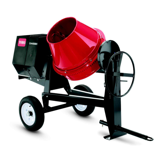
CM-Series Concrete Mixers
Model No. 68004—Serial No. 314000001 and Up
Model No. 68006—Serial No. 314000001 and Up
Model No. 68007—Serial No. 314000001 and Up
Model No. 68008—Serial No. 314000001 and Up
Model No. 68009—Serial No. 314000001 and Up
Form No. 3405-114 Rev A
G019544
*3405-114* A
Advertisement
Table of Contents

Related Manuals for Toro CM Series


Summary of Contents for Toro CM Series
- Page 1 Model No. 68004—Serial No. 314000001 and Up Model No. 68006—Serial No. 314000001 and Up Model No. 68007—Serial No. 314000001 and Up Model No. 68008—Serial No. 314000001 and Up Model No. 68009—Serial No. 314000001 and Up G019544 *3405-114* A Register at www.Toro.com. Original Instructions (EN)
- Page 2 You may contact Toro directly at www.Toro.com for product WARNING safety and operation training materials, accessory information, help finding a dealer, or to register your product. CALIFORNIA Proposition 65 Warning Whenever you need service, genuine Toro parts, or additional information, contact an Authorized Service Dealer or Toro...
-
Page 3: Table Of Contents
Contents Safety ................4 Figure 3 Safe Operating Practices........... 4 Safety and Instructional Decals ......... 7 1. Safety-alert symbol Setup ................10 1 Installing the Tow Pole..........10 This manual uses 2 words to highlight information. 2 Installing the Tongue ..........10 Important calls attention to special mechanical information 3 Installing the Safety Chain ........11 and Note emphasizes general information worthy of special Product Overview ............13... -
Page 4: Safety
Safety • Never let children or untrained people operate or service the equipment. Local regulations may restrict the age of the operator. Improperly using or maintaining the machine can result • The owner/user can prevent and is responsible for in injury. To reduce the potential for injury, comply with accidents or injuries to people or damage to property. - Page 5 Preparation – Ensure that the lug nuts are tight and torqued properly. Become familiar with the safe operation of the equipment, – Ensure that the machine is properly secured. operator controls, and safety signs. • Use only accessories and attachments approved by the Operation manufacturer.
- Page 6 Secure the machine from movement when storing the machine. • Keep all nuts, bolts, screws, and hose clamps securely tightened. Keep equipment in good condition. • Use only genuine Toro replacement parts to ensure that the original standards are maintained.
-
Page 7: Safety And Instructional Decals
Safety and Instructional Decals Safety decals and instructions are easily visible to the operator and are located near any area of potential danger. Replace any decal that is damaged or lost. 117-2718 125-8216 125-4940 1. Read the Operator’s 2. Warning—limit towing Manual for information on speed to less than 55 mph 1. - Page 8 125-4939 1. Warning—read the 4. Toxic gas inhalation Operator’s Manual. hazard—Don’t run the engine in an enclosed space. 2. Hand and arm 5. Explosion hazard—shut entanglement at the off the engine and keep belt drive; crushing hazard away from flames when of hand;...
- Page 9 132-4041 1. Read the Operator's Manual for more information on servicing the machine. 132-4042 1. Read the Operator's Manual for more information on servicing the machine.
-
Page 10: Setup
Setup Loose Parts Use the chart below to verify that all parts have been shipped. Procedure Description Qty. Install the tow pole (side-dump models Tow pole kit (sold separately) only). Tongue Front stabilizer leg Install the tongue (end-dump models Short bolt only). - Page 11 Installing the Tongue End-Dump Models Only Parts needed for this procedure: G021092 Tongue Figure 6 Front stabilizer leg 1. Front stabilizer leg Short bolt Long bolt 4. Install the tongue into the opening at the front of the machine and secure it with 6 nuts and short bolts torqued to 102 N∙m (75 ft-lb);...
-
Page 12: Installing The Safety Chain
Installing the Safety Chain End-Dump Models Only Installing the Safety Chain Parts needed for this procedure: Safety chain Connecting link Installing the Safety Chain Side-Dump Models Only Form a hook on the end of a bendable piece of rod or stiff wire, (not included), and install the safety chain as shown in Figure Figure 9... -
Page 13: Product Overview
Product Overview G019730 Figure 10 Side-Dump Models 1. Engine cowl 5. Tow pole 2. Engine switch 6. Safety-chain keyholes 3. Drum 7. Drum-tilt brake G019914 4. Handwheel 8. Rubber latch Figure 11 End-Dump Models 1. Tongue-mounted tow 7. Handwheel coupler 2. -
Page 14: Controls
Controls Become familiar with all of the controls before you start the engine and operate the machine. Engine Switch When the engine switch on the cowl is in the R position, it allows the engine to run. Moving the engine switch to the position shuts off the engine. -
Page 15: Specifications
Recoil-Start Handle Oil-Level Switch To start the engine, pull the recoil-start handle (Figure The oil-level switch is located inside the engine, and it does quickly to turn the engine over. The engine controls described not allow the engine to run in the event the oil level is below above must all be set correctly for the engine to start. - Page 16 G020836 Figure 17 1. Example of tire wear caused by underinflation G019733 Figure 16 Drum-Tilt Brake 1. Unlocked position 2. Locked position Figure 18 1. Example of tire wear caused by overinflation 4. Ensure that the engine cowl is closed and latched; refer Closing the Cowl (page 22).
- Page 17 7. Pull the clevis pin out from the front stabilizer leg and the tongue (Figure 21). G021 Figure 19 Raising the Stabilizer Legs End-Dump Models Only G019915 End-dump models have a front stabilizer leg and 2 rear Figure 21 stabilizer legs. 1.
- Page 18 Hitching a Machine with a Stamped Ball Hitching a Machine with a Forged Ball Coupler Coupler 1. Apply removable thread-locking compound to the 1. Apply chassis grease to the socket of the coupler and the area of the clamp that contacts the ball. threads of the coupler bolt to prevent the coupler handle from coming loose.
- Page 19 Hitching a Machine with a Pintle Hitch Hitching a Machine with a Pin Hitch Coupler Coupler 1. Hitch the machine as shown in Figure 1. Using a 19 mm (3/4 inch) or 22 mm (7/8 inch) hitch pin, hitch the machine as shown in Figure Figure 25 Figure 24...
- Page 20 Connecting the Safety Chains to the Important: Ensure that the chain has enough slack for turning around corners when towing the Tow Vehicle machine. 1. Pull the safety chain through the slots in the keyholes, Note: For side-dump models, stow the excess chain so that the lengths on each side are equal.
-
Page 21: Towing The Machine
Towing the Machine 3. Chock the front and back of the tires to prevent the machine from moving. WARNING 4. Ensure that the drum is in the mix position (upright). Towing the machine at high speed increases the 5. Ensure that the drum latch is engaged and that the risk of a hitch malfunction and tire failure. -
Page 22: Opening And Closing The Cowl
Closing the Cowl G019916 Figure 30 1. Remove the clevis pin. 3. Install the clevis pin. 2. Rotate the stabilizer leg down. 7. Rotate the front stabilizer leg down toward the ground (Figure 30). Figure 32 8. Push the clevis pin through the front hole in the tongue and the front stabilizer leg (Figure 30) and carefully... - Page 23 DANGER WARNING In certain conditions, fuel is extremely flammable Fuel is harmful or fatal if swallowed. Long-term and highly explosive. A fire or explosion from fuel exposure to vapors can cause serious injury and can burn you and others and can damage property. illness.
-
Page 24: Checking The Engine-Oil Level
4. Install the fuel cap securely (Figure 33). 5. Wipe up any fuel that may have spilled. Checking the Engine-Oil Level Before you start the engine and use the machine, check the oil level in the engine crankcase; refer to Checking the Engine-Oil Level (page 32). -
Page 25: Using The Machine
as the engine warms up. If the engine stalls or hesitates, move the choke lever toward the C position until the engine LOSED runs smooth. Allow the engine to warm up, then move the choke lever to the O position. Shutting Off the Engine 1. -
Page 26: Mixing The Material
Mixing the Material Mixing Pre-Mix Concrete 1. Ensure that the tilt brake is fully engaged and that the drum is operating at full speed. DANGER 2. Pour water into the drum. Eye and skin contact with concrete materials and 3. Add the required amount of dry pre-mix. breathing the dust involved is hazardous to your health. - Page 27 Note: Cleaning the paddles and drum between batches prevents material from drying and contaminating the next batch of material. Cleaning the Drum Service Interval: After each use Important: Do not strike on the drum with a shovel, hammer, or any other device to loosen any accumulated dried materials.
-
Page 28: Maintenance
Maintenance Important: Before performing any maintenance procedures, first stop the engine, wait 5 minutes to allow all moving parts to come to a complete stop and cool, and disconnect the spark-plug wire. Recommended Maintenance Schedule(s) Maintenance Service Maintenance Procedure Interval •... -
Page 29: Removing And Installing The Divider Plate
Removing and Installing the Installing the Divider Plate Divider Plate 1. Guide the divider plate into position against the front cowl. You need to remove the divider plate to provide access before Note: Start with the divider plate tilted slightly back, performing some maintenance procedures. -
Page 30: Lubrication
Lubrication Engine Maintenance Lubricating the Machine Servicing the Air Cleaner Service Interval: Monthly—Grease the trunnions and the Service Interval: Before each use or daily—Inspect the drum spindle. air-cleaner elements. 1. Clean around each grease fitting with a rag and lift the Every 50 hours—Clean the air-cleaner elements. -
Page 31: Servicing The Engine Oil
13. Securely install the cover with the nut. Servicing the Engine Oil Toro Premium Engine Oil is available from your Authorized Toro Dealer. Important: Use 4-cycle engine oil that meets or exceeds the requirements for API service category SJ, SL, SM, or higher . - Page 32 Checking the Engine-Oil Level Changing the Engine Oil Service Interval: Before each use or daily Service Interval: After the first 25 hours 1. Place the machine on a flat, level surface, and shut off Every 100 hours the engine. WARNING 2.
-
Page 33: Servicing The Spark Plug
Figure 47 1. Spark plug 2. Wire 4. Clean around the spark plug. 5. Rotate the spark plug counterclockwise using a 21 mm (13/16 inch) spark-plug wrench to remove the plug and the sealing washer (Figure 48). G019746 Figure 46 1. -
Page 34: Servicing The Spark Arrester
Note: If you see light brown or gray on the insulator, the Note: A spark arrester is available as an option. If you engine is operating properly. A black coating on the insulator require a spark arrester, contact your Authorized Toro Service usually means that the air cleaner is dirty. Dealer. -
Page 35: Fuel System Maintenance
Fuel System 6. Use a brush to carefully remove carbon deposits from the spark-arrester screen (Figure 51). Maintenance Note: Replace the spark arrester if it has breaks or holes. Cleaning the Fuel-Sediment Service Interval: Every 100 hours/Every 6 months (whichever comes first)—Clean the fuel-sediment cup. -
Page 36: Belt Maintenance
Belt Maintenance 10. Move the lever of the fuel valve to the O position (all the way to the right) and check for leaks. If it leaks, replace the O-ring. Checking the Drive-Belt Tension Service Interval: Every 20 hours—Check the drive-belt tension and adjust it as necessary. -
Page 37: Adjusting The Drive-Belt Tension
Replacing the Drive Belts 4. Measure the distance from the belt to the straightedge. The distance should be approximately 1 cm (13/32 Service Interval: Every 100 hours inch) as shown in Figure Note: The machine has 2 drive belts. Remember to buy 2 Note: If the belt tension needs adjustment, refer to belts for replacement. -
Page 38: Cleaning
Cleaning Storage Storing the Machine Cleaning the Machine For storage over 30 days, prepare the machine as follows: Regular cleaning and washing with mild detergent and water 1. Remove dirt and grime from the external parts of the increases the life span of the machine. Clean the machine entire machine, especially the engine. - Page 39 10. Paint all scratched or bare metal surfaces with paint available from your Authorized Toro Dealer. 11. Store the machine in a clean, dry garage or storage area. 12. Cover the machine to protect it and keep it clean.
-
Page 40: Troubleshooting
Troubleshooting Problem Possible Cause Corrective Action The engine does not start. 1. The engine switch on the cowl is in the 1. Press the engine switch to the R position. position. 2. The fuel valve is in the O position. 2. - Page 41 Notes:...
- Page 42 Notes:...
- Page 43 Notes:...
- Page 44 Toro importer. If all other remedies fail, you may contact us at Toro Warranty Company. Australian Consumer Law: Australian customers will find details relating to the Australian Consumer Law either inside the box or at your local Toro Dealer.
Need help?
Do you have a question about the CM Series and is the answer not in the manual?
Questions and answers