Table of Contents
Advertisement
Quick Links
Nu-Link-Gang
®
®
ARM
Cortex
-M0
32-bit Microcontroller
®
NuMicro
Family
Nu-Link-Gang
User Manual
The information described in this document is the exclusive intellectual property of
Nuvoton Technology Corporation and shall not be reproduced without permission from Nuvoton.
Nuvoton is providing this document only for reference purposes of NuMicro microcontroller based system
design. Nuvoton assumes no responsibility for errors or omissions.
All data and specifications are subject to change without notice.
For additional information or questions, please contact: Nuvoton Technology Corporation.
www.nuvoton.com
Dec. 23, 2019
Page 1 of 37
Rev 1.00
Advertisement
Table of Contents

Related Manuals for Nuvoton NuMicro Nu-Link-Gang


Summary of Contents for Nuvoton NuMicro Nu-Link-Gang
- Page 1 The information described in this document is the exclusive intellectual property of Nuvoton Technology Corporation and shall not be reproduced without permission from Nuvoton. Nuvoton is providing this document only for reference purposes of NuMicro microcontroller based system design. Nuvoton assumes no responsibility for errors or omissions.
- Page 2 Nu-Link-Gang Supported devices of Nu-Link-Gang Cortex-M0 series M031 M051 M0518 M0519 M0564 M058S Mini51 Mini51X Mini57 Mini58 NM1120 NM1200 NM1230 NM1320 NM1330 NM1500 NM1810 NM1820 TF5100 Nano100 Nano103 NDA102 NUC029 NUC100 NUC121 NUC126 NUC131 NUC200 AU9110 I91000 N569 N570 N572 N575 N576 Cortex-M4 series...
-
Page 3: Table Of Contents
Control Bus ........................9 2.1.8 Upgrade Interface ......................9 Nuvoton ICP Gang Adapter ..................10 2.2.1 Status LED ........................10 Nuvoton NUC505 ICP Gang Adapter ................. 11 2.3.1 IC Mode Switch ......................11 2.3.2 Status LED ........................12 NU-LINK-GANG PROGRAMMER SETUP ................13 Choose the Programming Voltage ................ - Page 4 Nu-Link-Gang 4.7.1 Programming ........................23 4.7.2 LCD Display ........................23 NU-LINK-GANG PROGRAMMER SETUP FOR AUTOMATIC IC PROGRAMMING SYSTEM ............................25 Software and Hardware Setup ................... 25 5.1.1 Connection ........................25 5.1.2 Waveform ........................26 NU-LINK-GANG PCB SCHEMATIC ..................27 Control Unit Schematic....................27 Power and Connection Schematic ................
-
Page 5: General Description
User can connect the Nu- Link-Gang programmer and target chips by using a automatic IC programming system, Nuvoton ICP Gang Adapters or customize adapter boards. Different ICs or different packages use different Nuvoton ICP Gang Adapters. -
Page 6: Hardware Introduction
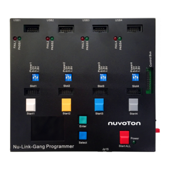
Nu-Link-Gang HARDWARE INTRODUCTION Nu-Link-Gang Programming Unit #1 ~ #4 (Top) USB Connector Adaptor Board Aid Connector Status LED Programming Voltage Switch Adaptor Board Connector Single-start Button LCD Control Button LCD Display (Bottom) Upgrade interface Power LED All-start Button Programming Mode Switch Control Bus Power Button... -
Page 7: Programming Unit
Nu-Link-Gang 2.1.1 Programming Unit Programming unit #1, #2, #3, and #4, four independent units with identical functions. Programming unit USB Connector USB1 USB2 USB3 USB4 FAIL1 FAIL2 FAIL3 FAIL4 Status LED PASS1 PASS2 PASS3 PASS4 Programming Power1 Power2 Power3 Power4 Voltage Switch Adapter Board Slot1... -
Page 8: Programming Mode Switch
Figure 2-4 Programming Voltage Switch Table 2-3 Programming Voltage Switch 2.1.6 Status LED The status LEDs on the Nu-Link-Gang and the Nuvoton ICP Gang Adapter show the programming results of every unit. Dec. 23, 2019 Page 8 of 37 Rev 1.00... -
Page 9: Control Bus
Nu-Link-Gang Light Status Green PASS FAIL Figure 2‑5 Status LED Table 2-4 Status LED on Nu-Link-Gang 2.1.7 Control Bus The Nu-Link-Gang can be connected to a automatic IC programming system through the control bus. Figure 2‑6 Control Bus 2.1.8 Upgrade Interface JP15 is the SWD interface only for the Nu-Link-Gang firmware upgrade. -
Page 10: Nuvoton Icp Gang Adapter
LED2 LED4 LED6 LED8 Table 2-5 Nuvoton ICP Gang Adapter Component List 2.2.1 Status LED The status LEDs on the Nu-Link-Gang and the Nuvoton ICP Gang Adapter show the programming results of every unit. Light Status Green PASS FAIL Figure 2‑9 Status LED Table 2-6 Status LED on Nuvoton ICP Gang Adapter Dec. -
Page 11: Nuvoton Nuc505 Icp Gang Adapter
Nuvoton NUC505 ICP Gang Adapter Table 2-7 Nuvoton NUC505 ICP Gang Adapter Component List 2.3.1 IC Mode Switch The IC mode switch on the NUC505 Nuvoton ICP Gang Adapter must be set before programming process. Please refer to chapter 4. Mode Mode 1... -
Page 12: Status Led
Nu-Link-Gang 2.3.2 Status LED The status LEDs on the Nu-Link-Gang and the Nuvoton ICP Gang Adapter show the programming results of every unit. Light Status Green PASS FAIL Figure 2‑12 Status LED Table 2-9 Status LED on Nuvoton NUC505 ICP Gang Adapter Dec. -
Page 13: Nu-Link-Gang Programmer Setup
NuMicro ICP tool - ICP Programming Tool. Unzip the file and execute “NuMicro ICP Programming Tool.exe”. Please refer to section 3.3.1 and 3.3.2 for the detailed flow. For more information, please refer to the “Nuvoton NuMicro ICP Programmer User Guide”. 3.3.1 Connect to ICP Programming Tool Connects one programming unit’s to PC through USB connector as Figure 3-1, then open the ICP... -
Page 14: Import/Export Project
Nu-Link-Gang Load the firmware image files to the corresponding flash region. Set the Config Bits by the using IC series. Select the programming area. Set the program option. It is necessary to select the “Offline Programming Mode” option. Click “Start”. The ICP Programming Tool will start loading the firmware image files to the Nu- Link-Gang. -
Page 15: Connect To The Target Chip
Connect to the Target Chip 3.4.1 Nuvoton ICP Gang Adapter Connect the Nuvoton ICP Gang Adapter to Nu-Link-Gang as Figure 3-4. Put the target chip into the socket. Pin 1 is on the bottom-left hand side. Figure 3-4 Nuvoton ICP Gang Adapter with Nu-Link-Gang 3.4.2... -
Page 16: Start Programming
To start the programming process, press the Start ALL button or the individual Start button depends on the programming mode switch setting. The status LEDs on the Nu-Link-Gang and the Nuvoton ICP Gang Adapter will show the programming results of every unit. - Page 17 Nu-Link-Gang Page 3: Shows programming unit Information as Figure 3-9. List the programming chip’s part number, programming unit’s version number, maximum programmable times, PASS/FAIL status records, and error code. Press Enter button to go to the next page. Page 4: Shows programming unit Information as Figure 3-10.
- Page 18 Nu-Link-Gang Checksum Value Enter Button Config Bit Select Button Page Figure 3-10 Page 4 - Programming Unit Information Connects the Nu-Link-Gang to the target chip before to the computer, and then config the ICP Programming Tool as 3.3, the part number of the target chips will shows on the LCD display as Figure 3-11 and Figure 3-12.
-
Page 19: Nu-Link-Gang Programmer Setup For Nuc505 Series
4.3.1 Nuvoton NUC505 ICP Gang Adapter Connect the Nuvoton NUC505 ICP Gang Adapter to Nu-Link-Gang as Figure 4-1. Put the target chip into the socket. Pin 1 is on the bottom-right hand side, marked in white arrow. Figure 4-1 Nuvoton NUC505 ICP Gang Adapter with Nu-Link-Gang Dec. -
Page 20: Customized Adapter Board
Nuvoton Technology Corporation for adapter board specifications. Figure 4-2 Slot Pin Description IC Mode Switch Switch four programming units’ IC mode to Mode 1 on the Nuvoton NUC505 ICP Gang Adapter as Figure 4-3. Figure 4-3 IC Mode in Mode 1 ®... -
Page 21: Icp Programming Tool Setting
Nu-Link-Gang Figure 4-4 Nu-Link-Gang Connects to PC 4.5.2 ICP Programming Tool Setting Choose “Connect”. The window will shows “NuLink connected” when the connection between programming unit and ICP Programming Tool is built. Load the firmware image files to the corresponding flash region. Set the program option. -
Page 22: Import/Export Project
It can also do the binary code protection through exporting with a ceritificate. Figure 4-6 ICP Programming Tool Import/Export Project IC Mode Switch Switch four programming units’ IC mode to Mode 2 on the Nuvoton NUC505 ICP Gang Adapter as Figure 4-7. Dec. 23, 2019 Page 22 of 37 Rev 1.00... -
Page 23: Start Programming
Press the Start ALL button or the individual Start button depends on the programming mode switch setting to start the programming process. The status LEDs on the Nu-Link-Gang and the Nuvoton NUC505 ICP Gang Adapter will show the programming results of every unit. Change the target chip in the adapter, and repeat section 4.6 process. - Page 24 Nu-Link-Gang Figure 4-9 LCD Display Dec. 23, 2019 Page 24 of 37 Rev 1.00...
-
Page 25: System
Nu-Link-Gang NU-LINK-GANG PROGRAMMER SETUP AUTOMATIC PROGRAMMING SYSTEM Software and Hardware Setup Follow section 3.1 and 3.3 to setup the programming voltage and firmware image file for four programming units individually. Switch the programming mode to single-start. 5.1.1 Connection Each programming units connects to the automatic IC programming system through individual slot and the control bus as Figure 5-1. -
Page 26: Waveform
Nu-Link-Gang 5.1.2 Waveform The Nu-Link-Gang power on. STARTx, BUSYx, PASSx, and FAILx are set to logic 1. To start programming, STARTx needs to be set to logic 0 for TSTART, Programming start-up. BUSYx is set to logic 0 , and might toggle during programming. When finish programming, BUSYx is set to logic 1, and PASSx or FAILx is set to logic 0. -
Page 27: Nu-Link-Gang Pcb Schematic
Nu-Link-Gang NU-LINK-GANG PCB SCHEMATIC Control Unit Schematic VCC33 Link1_VCC Link1_VCC Link2_VCC Link2_VCC Link3_VCC ADAVSS Link3_VCC Link4_VCC Link4_VCC Link4_VCC All_KEY All_KEY All_KEY M_Trigger1 M_Trigger1 M_Trigger2 M_Trigger2 M_Trigger3 RKSP86-N-A0-00(Red) M_Trigger3 All Button Control M_Trigger4 M_Trigger4 LCM_DC PB.9/TM1 LCM_DC LCM_RESET VCC33 LCM_RESET PB.10/TM2 LCM_LED LCM_LED PB.11/TM3/PWM0_CH4... -
Page 28: Power And Connection Schematic
Nu-Link-Gang Power and Connection Schematic JP31 M_Trigger1 VCC33 M_Trigger1 M_Trigger2 choke AMS1117 3.3V M_Trigger2 M_Trigger3 M_Trigger3 M_Trigger4 M_Trigger4 5VCC KEY 1 MC7805CT(TO-220) KEY 1 VCC33 JP21 KEY 2 KEY 2 Power_VDD KEY 3 D C 5V I nput KEY 3 KEY 4 FERRITE BEAD KEY 4... -
Page 29: Nulink Schematic
Nu-Link-Gang #1 NuLink Schematic 3VCC_1 BUSY 1 3VCC_1 BUSY 1 3VCC_1 AVDD1 M_Trigger1 M_Trigger1 12M_O UART_RXD_A UART_RXD_A 8P4R-330 UART_TXD_A UART_TXD_A ICELED KEY 1 KEY 1 ICE1 RED(SMD) Link1_VCC Link1_VCC PVSS KEY 1 12MHz 3VCC_1 ICPLED AVDD1 ICP1 Y ELLOW(SMD) FERRITE BEAD 12M_I IDLE1 FERRITE BEAD... -
Page 30: Nulink Schematic
Nu-Link-Gang #2 NuLink Schematic 3VCC_2 BUSY 2 3VCC_2 BUSY 2 3VCC_2 AVDD2 M_Trigger2 M_Trigger2 12M_O UART_RXD_B UART_RXD_B 8P4R-330 UART_TXD_B UART_TXD_B ICELED KEY 2 KEY 2 Link2_VCC ICE2 RED(SMD) Link2_VCC PVSS KEY 2 12MHz 3VCC_2 ICPLED AVDD2 ICP2 Y ELLOW(SMD) FERRITE BEAD 12M_I IDLE1 FERRITE BEAD... -
Page 31: Nulink Schematic
Nu-Link-Gang #3 NuLink Schematic 3VCC_3 BUSY 3 3VCC_3 BUSY 3 3VCC_3 AVDD3 M_Trigger3 M_Trigger3 12M_O UART_RXD_C UART_RXD_C 8P4R-330 UART_TXD_C UART_TXD_C ICELED KEY 3 KEY 3 Link3_VCC ICE3 RED(SMD) Link3_VCC PVSS KEY 3 12MHz 3VCC_3 ICPLED AVDD3 ICP3 Y ELLOW(SMD) FERRITE BEAD 12M_I IDLE1 L10 FERRITE BEAD... -
Page 32: Nulink Schematic
Nu-Link-Gang #4 NuLink Schematic 3VCC_4 BUSY 4 3VCC_4 BUSY 4 3VCC_4 AVDD4 M_Trigger4 M_Trigger4 12M_O UART_RXD_D UART_RXD_D 8P4R-330 UART_TXD_D UART_TXD_D ICELED KEY 4 KEY 4 Link4_VCC ICE4 RED(SMD) Link4_VCC PVSS KEY 4 12MHz 3VCC_4 ICPLED AVDD4 ICP4 Y ELLOW(SMD) L12 FERRITE BEAD 12M_I IDLE1 L13 FERRITE BEAD... -
Page 33: Lcd Display Schematic
Nu-Link-Gang LCD Display Schematic LCM_VCC_Ctrl LCM_VCC_Ctrl LCM_DC LCM_DC LCM_RESET LCM_RESET PC6=RESET LCM_LED PC9=CLK LCM_LED PC15=DC LCM_SPI_SS SPI0_CS# LCM_SPI_CLK PC8=SS SPI0_CLK LCM_RESET LCM_SPI_MISO SPI0_DI PC11MOSI LCM_SPI_CLK LCM_SPI_MOSI SPI0_DO LCM_DC PC10=MISO LCM_SPI_SS LCM_SPI_MOSI PA12=LCD_Ctrl LCM_SPI_MISO PC14=LED LCM_VCC_Ctrl VCC33 VCC33 LCM_LED HEADER 10(2.0母座) HEADER 10(2.0母座) 100K 改10K Big Buttom... -
Page 34: Troubleshooting
When pop-up warning message shows as Figure 7-1 while programming NUC505 series, please check all four programming units’ IC mode is set to Mode 1 on the Nuvoton NUC505 ICP Gang Adapter and press Reset button. If the warning message still pop-up, please check the NUC505 chip is placed currectly. - Page 35 Nu-Link-Gang Figure 7-2 Pop-up Warning Message Figure 7-3 Programming Unit Firmware Update Dec. 23, 2019 Page 35 of 37 Rev 1.00...
-
Page 36: Revision History
Nu-Link-Gang REVISION HISTORY Date Revision Description 2019.12.23 1.00 Preliminary version. Dec. 23, 2019 Page 36 of 37 Rev 1.00... - Page 37 Nu-Link-Gang Important Notice Nuvoton Products are neither intended nor warranted for usage in systems or equipment, any malfunction or failure of which may cause loss of human life, bodily injury or severe property damage. Such applications are deemed, “Insecure Usage”.
Need help?
Do you have a question about the NuMicro Nu-Link-Gang and is the answer not in the manual?
Questions and answers