Solar-Log 250 Manual
Hide thumbs Also See for 250:
Table of Contents

Advertisement

Manual V.4.2.7
EN
Solar-Log™
1

Advertisement

Table of Contents
loading
Need help?

Need help?

Do you have a question about the 250 and is the answer not in the manual?

Questions and answers

Subscribe to Our Youtube Channel

Summary of Contents for Solar-Log 250

  • Page 1 Manual V.4.2.7 Solar-Log™...
  • Page 2 Publisher: Solare Datensysteme GmbH Fuhrmannstr. 9 72351 Geislingen-Binsdorf Germany International support Tel.: +49 (0)7428/4089-300 e-mail: info@solar-log.com Contact: https://www.solar-log.com Italy Technical support: +39 0471 631032 France Technical support: +33 97 7909708 Switzerland Technical support: +41 565 355346 United States Technical support: +1 203 702 7189...
  • Page 3: Table Of Contents

    RS485-A (only Solar-Log 1200, 1900 and 2000) ................... 25 RS485/422 - B .............................. 26 RS485/422 - C (only Solar-Log 1900 and 2000) ..................... 27 S0 .................................. 28 9.5.1 S0 OUT / IN A (S0-OUT and S0-IN A) (except Solar-Log 250) ................28 9.5.2 S0-IN B ................................29...
  • Page 4 11.6 Wiring for S0 meter ............................ 43 11.7 Wiring for RS485 meter .......................... 45 11.8 Installation Utility Meter / Janitza UMG 104 / UMG 604 (only Solar-Log 1900 and 2000) ..... 47 11.9 Solar-Log™ Smart Relay Box ......................... 51 11.10 WeMo Insight Switch ............................. 53 11.11...
  • Page 5 16.5.2 Device notifications ............................110 16.6 Yield mail .............................. 112 16.6.1 Explanation of the individual E-mail Functions: ..................114 16.6.2 Text message (SMS) notifications ....................... 116 16.7 Alarm (only Solar-Log 1900 and 2000) .....................  116 16.8 Power & Failure ............................ 117 16.8.1 General Information on Performance Monitoring .................. 119 16.9 PM .................................  123 16.10...
  • Page 6 16.13.1 Reactive power deactivated ........................151 16.13.2 Fixed value cos (Phi) shift factor .........................152 16.13.3 Fixed reactive power in Var .........................152 16.13.4 Variable cos (Phi) shift factor over characteristic curve P/Pn ..............153 16.13.5 Variable shift factor cos(Phi) (U) (only Solar-Log 1900 PM+ and 2000 PM+ with Utility Meter) ..154 16.13.6 Variable reactive power via the characteristic curve Q(U) (only Solar-Log 1900 and 2000 with Utility Meter) ................................155 16.13.7 Remote-controlled fixed value cos (Phi) shift factor (only Solar-Log™ PM+) .........158 16.13.8 Linking (only Solar-Log 1900 and 2000) .....................160 16.13.9 Profile ................................161...
  • Page 7 17.5.2 Explanation of the Symbols in the Feed-in power (% DC) column: .............194 17.5.3 Explanation of the Values in the Reactive Power Reduction Section ............194 17.5.4 Feed-Balance ..............................197 17.5.5 PM History................................198 17.6 Accessing the SCB Monitor (only Solar-Log 1900 and 2000) .............. 199 17.7 Accessing components ............................ 200 17.8 Smart Energy .............................. 201 17.8.1 Explanations of the Tabs ..........................202...
  • Page 8 19.2 Accessing Yield history ............................ 244 19.3 Accessing Environmental performance ...................... 244 19.4 Settings on the device ............................ 245 19.4.1 Start menu (only Solar-Log 1200) ........................245 19.4.2 Basic settings menu .............................252 19.4.3 USB menu ................................253 19.4.4 Advanced settings menu .............................256 19.5 Error and Fault Messages on the Display ...................... 261 20 Notifications on the LCD Status Display ����������������������������������������������������������262 20.1...
  • Page 9 Appendix ���������������������������������������������������������������������������������������������������������282 25.1 Internet ports .............................. 282 25.2 Country specific inverter detection with Easy Installation...............  283 25.3 Wiring meters to record self-consumption .................... 284 25.3.1 Meter connection options to record the total consumption via an RS485/S0 interface....... 284 25.3.2 Meter connection options for bi-directional recording of the total consumption via only an RS485 interface................................285 25.4 Connection examples for ripple control receivers.................. 286 25.4.1 Variation with 4 relays (ENBW >100kWp) ....................287 25.4.2 Variation with two relays ..........................289 25.4.3 Variation with three relays ..........................
  • Page 10: Introduction

    Introduction 1 Introduction This installation manual is intended for use by solar energy technicians and professional electricians, as well as Solar-Log™ users. It should be noted that the installation and commissioning of the individual compo- nents is only to be performed by properly trained specialists. Refer to Chapter 4 “Safety information” for more information. The wiring for the devices is described in detail in the Component Installation Manual. The Solar-Log™ must only be used by persons who have fully read and understood the manual before installing, operating and/or servicing the device.
  • Page 11: Notes For The Firmware Update

    Notes for the Firmware Update 2 Notes for the Firmware Update The following models may be updated to the Solar-Log™ Firmware Version 4.2.7 • Solar-Log 50 (see Solar-Log 50 - manual on our homepage: https://www.solar-log.com/en/support/downloads/ manuals) • Solar-Log 250 •...
  • Page 12: Safety Information

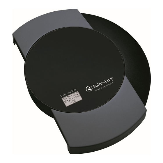
    Note! The Solar-Log 300 functions described in this manual are essentially identical to those of the Solar-Log 250. Refer to the Solar-Log 250 data sheet for the differences.
  • Page 13: Electric Current

    Avoid contact with component connections and plug contacts. Before picking up the component, ground yourself by holding the protective conductor (PE) or the unpainted part of the inverter housing. Caution! Damage to the electrical components of the Solar-Log™ due to the wiring of the Solar-Log™! Switch the Solar-Log™ off; See Chapter 11.1 on page 32 Caution! Risk of electric shock. Do not use the unit if the housing of the external power supply unit is damaged. A damaged power supply unit must be replaced by one of the same type and from the same manufactu- rer in order to avoid danger.
  • Page 14: Package Contents

    Check the package contents before proceeding to assembly and install. Report any damage or missing parts to the forwarding agent and dealer immediately. The unit is supplied with the following components: • Solar-Log™ basic unit • 2x cover panels to be fitted to the top and bottom of the unit to protect the connections and reset button • 12 V power supply with country-specific adapters •...
  • Page 15: Wall Mounting

    The device is produced according to protection class IP20 and is intended only for installation in interior areas that are dry and dust-free. Suitable wall plugs and screws are supplied for wall mounting. Please remember that an electrical outlet and a local network connection are required near the Solar-Log™ in order for it to operate. • Put the housing where it is to be fitted and mark the drill holes.
  • Page 16 Wall mounting • Cable feed through – top and/or bottom covers. Using a file or a saw, clear the cable feed holes. The top and bottom covers are identical. • Plug all cable connectors into their connections. • Attach the covers...
  • Page 17: Unit Connections

    S0 connection. USB connection. Suitable for USB sticks. Not suitable for a connection to a PC S0-IN B S0 pulse input for connection to an external power meter. *Only the Solar-Log 300 is equipped with this connection.
  • Page 18: Fig.: Bottom Connections Solar-Log 300 / 250

    Unit connections Bottom connections Fig.: Bottom connections Solar-Log 300 / 250 Solar-Log 300 / Solar-Log 250 RS485/422 - B RS485 interface, 6 pin: Connection for inverters and additional accessories Power 12 V 12 volt DC input Network Ethernet network interfa- ce, 10/100 Mbit...
  • Page 19: Solar-Log 1200

    Unit connections 7�2 Solar-Log 1200 Top connections Fig.: Top Connections Solar-Log 1200 Solar-Log 1200 S0-Out S0 pulse output for S0-IN A connecting to a large external display. S0 pulse input for connection to an external power meter. Please note the connection characteristics of the S0 connection.
  • Page 20: Fig.: Top Connections Solar-Log 1200

    Unit connections Bottom connections Fig.: Top Connections Solar-Log 1200 Solar-Log 1200 Relay Relay with change-over contact RS485 - A RS485 interface, 4 pin: Connection for inverters and/or accessories (inacti- ve if the optional Bluetooth interface is used) RS485/422 - B RS485 interface, 6 pin: Connection for inverters and additional accessories Power 12 V...
  • Page 21: Solar-Log 1900/2000

    Unit connections 7�3 Solar-Log 1900/2000 Top connections Fig.: Top Connections Solar-Log 1900/2000 Solar-Log 1900/2000 S0-Out S0 pulse output for connec- S0-IN A ting to a large external screen. S0 pulse input for connection to an external power meter. Please note the connection characteristics of the S0 connection.
  • Page 22: Fig.: Top Connections Solar-Log 1900/2000

    Unit connections Bottom connections Fig.: Top Connections Solar-Log 1900/2000 Solar-Log 1900/2000 Relay Relay with change-over contact RS485 - A RS485 interface, 4 pin: Connection for inverters and/or accessories (inacti- ve if the optional Bluetooth interface is used) RS485/422 - B RS485 interface, 6 pin: Connection for inverters and additional accessories Power 12 V...
  • Page 23: Optional Connections

    Optional Connections 8 Optional Connections Solar-Log™ devices are available as different models which can be equipped accordingly with additional interfaces and connections depending on the application. 8�1 Solar-Log™ PM+ Fig.: 6-pin PM+ interface Assignment Description Control voltage for active power control D_IN_1 Control input 1 D_In_2 Control input 2 D_In_3 Control input 3 D_In_4 Control input 4 Control voltage for reactive...
  • Page 24: Connector Assignments And Wiring

    If you want to connect several inverters to Solar-Log™, you need suitable cables and connectors to connect the inverters to each other. • For each connection to the Solar-Log™ (RS485 - A and RS485/422 - B or - C) a separate cable must be used. • When wiring with CAT cables, the twisted pair of wires should be used. 9�1 Notes on wiring the connections The wiring of the inverters and accessories needs to be carried out with the greatest care and attention. The most...
  • Page 25: Rs485-A (Only Solar-Log 1200, 1900 And 2000)

    Connector Assignments and Wiring Fig.: Terminal block connector with ferrules 9�2 RS485-A (only Solar-Log 1200, 1900 and 2000) Use the provided terminal block connectors when connecting inverters or accessories to the RS485 A interface. Fig.: 4-pin Terminal block connector RS485 - A Assignment Data + 12 V Ground Data -...
  • Page 26: Rs485/422 - B

    Connector Assignments and Wiring 9�3 RS485/422 - B Use the provided terminal block connectors when connecting inverters or accessories to the RS485/422 - B interfa- Fig.: 6-pin Terminal block connector RS485/422 - B Assignments RS485 Assignments RS422 Data + T/RX+ 12 V Ground Ground Data - T/RX- R/TX+ R/TX- Note! If inverters that use the RS422 connection are connected to this interface (e.g. Fronius, AEG, Riello), then it is not possible to connect accessories such as sensors, meters or displays to this bus.
  • Page 27: Rs485/422 - C (Only Solar-Log 1900 And 2000)

    Connector Assignments and Wiring 9�4 RS485/422 - C (only Solar-Log 1900 and 2000) Use the provided terminal block connectors when connecting inverters or accessories to the RS485/422 C interfa- Fig.: 6-pin Terminal block connector RS485/422 C Assignments RS485 Assignments RS422 Data + T/RX+ 12 V Ground Ground Data - T/RX- R/TX+ R/TX- Note! If inverters that use the RS422 connection are connected to this nterface (e.g. Fronius, AEG, Riello), then it is not possible to connect accessories such as sen-...
  • Page 28: S0 Out / In A (S0-Out And S0-In A) (Except Solar-Log 250)

    SO_OUT_IN A interface (S0-OUT and S0-IN A) and • S0-IN B 9�5�1 S0 OUT / IN A (S0-OUT and S0-IN A) (except Solar-Log 250) The S0_OUT_IN interface is a hardware interface used for recording measurement values from power meters and an output for S0 pulses. Use the supplied terminal block connector for the connection to the Solar-Log™. S0_OUT_IN A Assignment 27 mA output 27 mA max. input...
  • Page 29: S0-In B

    Connector Assignments and Wiring 9�5�2 S0-IN B The S0 In interface is a hardware interface used for recording measurement values from power meters. Use the supplied terminal block connector for the connection to the Solar-Log™. Fig.: 4-pin Terminal block connector S0-IN B Assignment S0 + Output 27mA S0 - Input max 27mA Measuring contact Ground Installation instructions for external power meters are also in chapter „12.5 External power meters“ on page 41.
  • Page 30: Fig.: 4-Pin Terminal Block Connector

    Connector Assignments and Wiring 9�6 PM+ The Solar-Log™ PM+ models come with a 6-pin PM+ interface on the top side of the Solar-Log The interface has been designed to link the ripple control receivers or telecontrol plants with potential-free signal contacts. Up to two ripple control receivers can be connected. This allows the commands from grid operators for active and reactive power to be interpreted. Fig.: 6-pin PM+ interface Fig.: 6-pin Terminal block connector Assignment Description Control voltage for active power control...
  • Page 31: 10 Connecting The Inverters

    Connecting the inverters 10 Connecting the inverters As each inverter manufacturer uses different wiring connections and connectors, the corresponding data cables must be adapted correctly. • See Chapter„Connector Assignments and wiring“ for terminal block connector wiring diagrams for the connec- tion to the Solar-Log™ • Please refer to the Component Connection Manual when connecting inverters supported by the Solar-Log™. Note! Solare Datensysteme GmbH supplies suitable connection cables for most inverter manufactu- rers. Always read the manufacturer-specific instructions for connecting the data cable. You will find these instructions in the manufacturer's documentation.
  • Page 32: Switch Off The Inverters And The Solar-Log

    Connecting the inverters 10�1 Switch off the inverters and the Solar-Log™. Switching inverters off Before a making a cable connection between the Solar-Log™ and the connections inside the inverter and before installing an interface card in the inverter, always turn off all of the inverters first. To do this, read the manufacturer's documentation for the inverter, and proceed as follows: • Disconnect the AC side • Disconnect the DC side • Wait at least 5 minutes until the condensers in the inverters have discharged. Turn the Solar-Log™ off. • Unplug the power socket connection...
  • Page 33: 11 Connecting Accessories

    In other cases, a suitable fitting support may have to be added. Note! When using inverters with RS422 communication, do not operate the sensor on the same bus. Wiring the Sensor Box Basic and Professional to the Solar-Log™ The wiring is done using a • 4-wire data cable which also includes the 12 V power supply and the data connection to the Solar-Log™.
  • Page 34 2 (+12V) Red: 12 V (VCC) 3 (Ground) Black: 0V (GND) 4 (Data -) Orange: Data - Installation When the Solar-Log™ is switched on, the sensor is also automatically powered. Then the Sensor Basic and Professional have to be configured to the desired RS485 interface: • Select the "Mencke&Tegtmeyer" sensor via the device definition according to the device class and manufactu- rer. • Define the bus. • Perform device detection.
  • Page 35: Sensor Box Professional Plus

    The Sensor Box Professional Plus is used to record the Irradiation from the sun. This accessory allows the So- lar-Log™ to calculate the deviations in the current output compared to the potential output. Up to 9 Sensor Box Professional Pluses can be connected to the Solar-Log™. The solar radiation sensor must be fitted in such a way that the sensor's solar cell and the plant's modules are aligned as similarly as possible to the sun, i.e. the sensor must have the same alignment and inclination.
  • Page 36 Database. The Sensor Box Professional Plus is connected to the Solar-Log using the RS485 interface. The connection cable between the Sensor Box Professional Plus and the Solar-Log consists of 4 wires and inclu- des the 12 volt power supply and the data connection to the Solar-Log The cable shielding must be connected with an equipotential bonding system.
  • Page 37 4 (Data -) Orange: Data - B Installation When the Solar-Log™ is switched on, the Sensor Box Professional Plus is also automatically powered. Then the Sensor Box Professional Plus must be configured to the desired RS485 interface: • Select "M&T Sensor" and the corresponding bus for the initial configuration.
  • Page 38: Ripple Control Receiver

    Connecting accessories 11�3 Ripple Control Receiver The Solar-Log™ PM+ series contains an additional 6-pin interface which allows up to two ripple control receivers or telecontrol plants each with four signals to be connected. Wiring The relay contacts for the ripple control receiver are connected to the Solar-Log™ PM+ via the 6 pin PM+ interface on the top side of the Solar-Log™. Fig.: 6-pin PM+ interface The ripple control receivers used by grid operators utilize various numbers of relays. These relays are labeled differently and have different reduction levels and/or shift factors cos (Phi). To ensure the highest degree of flexibility, the reduction levels specified by the grid operators, together with their signals from the ripple control receiver, can be evaluated by the Solar-Log™ via a maximum of four digital inputs for each. In order that the Solar-Log™ PM+ can evaluate the signal from the ripple control receiver, it needs to be wired to the control voltage (for active and reactive power) from the PM+ interface. The control contracts normally operate as make contracts; that means they are closed for the respective command. The control voltage from Pin 1 is used for the active power command. The control voltage from Pin 6 is used for the reactive power command.
  • Page 39: Large External Displays

    • Connection via RS485 • S0 pulse output The connection via RS485 is preferred Cable lengths can be up to 1000 meters and the data which is displayed on the Solar-Log™ can specified. Note! It is not possible to connect a large external display on the RS485 / 422 C interface. Note! If inverters that use the RS422 connection are connected to this interface (e.g. Fronius, AEG, Riello), then it is not possible to connect a display to this bus.
  • Page 40 Connecting accessories Wiring for displays from RiCo Electronic The wiring consists of a 2-pin control cable, (2x0.5 mm ) and terminal block connector. RiCo Large displays RS485 Solar-Log™ Terminal block connector RiCo Display Assignment 1 (Data +) Pin 1 - Data +...
  • Page 41: External Power Meter

    This mode is used to measure power consumption and to make it possible to display this data and to use Smart Energy functions. • Utility Meter (U) (only Solar-Log 1900 and 2000) This mode is used for voltage measurements for reactive power control with the characteristic curve Q(U). • Utility Meter (U+I) (only Solar-Log 1900 and 2000) This mode is used to record the measurement data needed for the response signals sent to the grid operator and for cos phi control at the feeding point.
  • Page 42: External Power Meters/Accumulating Meters

    Connecting accessories 11�5�1 External power meters/accumulating meters With multiple phase meters, a basic distinction is made between phase-exact and accumulating meters. Accumulating meters provide the total values from all three phases. The meter calculates the total output (also to and from the grid) of the individual phases and provides this total as a single value. In the example: Phase 1 supplies 3 kW via an inverter (single phase). Phase 2 refers to 2 kW (energy) Phase 3 refers to 1 kW (energy) With an accumulating meter, this results in a total of 0 kW. Examples of accumulating meters are the Janitza UMG 104 and the Inepro Pro380-Mod.
  • Page 43: Wiring For S0 Meter

    SO meters in general Power meter Solar-Log™ Assignment Place a cable bridge between pin 3 and 4 on the Solar-Log™. The maximum cable length between the power meter and Solar-Log™ is 10 meters. Wiring for Inepro 75D meter via S0 Article Number: 255420 Inepro 75D Power meter Solar-Log™...
  • Page 44 Article Number: 255421 Inepro 1250D Power meter Solar-Log™ Assignment Pin 9 - S0+ Pin 8 - S0- Place a cable bridge between pin 3 and 4 on the Solar-Log™. Wiring for Iskra WS0021 meter via S0 Article Number: 255346 Iskra WS0021 Power meter Solar-Log™ Assignment Pin 9 - S0- Pin 8 - S0+ Place a cable bridge between pin 3 and 4 on the Solar-Log™.
  • Page 45: Wiring For Rs485 Meter

    11 - 485A 22 - B 7 - 485B 10 - 485B 23 - A • Insert the terminal block connector into the Solar-Log™ RS485 A, RS485/422 B or RS485/422 C socket. • Perform a device detection: The power meter is connected to the system as if it were an inverter. • Configuration | Device | Configuration Configure the power meter functions under .
  • Page 46 Note! Inepro meter Inepro meters are automatically given the mod bus address 234 by Solar-Log™ during the detection process. This address is therefore not allowed to be used for other devices. After the configuration, the display on the Inepro meter alternates between the meter status and the address display (ID=EA). This can be used to check if Solar-Log™ has correctly detected the meter. All RS485 meters have to be terminated with an 120Ω resistor between the two pins used.
  • Page 47: Installation Utility Meter / Janitza Umg 104 / Umg 604 (Only Solar-Log 1900 And 2000)

    The Utility Meter that we use is produced by the company Janitza. Refer to the Janitza UMG 104 / UMG 604 manual for further technical details. We cannot guarantee the functionality of other Janitza devices. => The operating modes Utility Meter (U / U+I) are only possible with the Solar-Log 1900 and 2000. Note! The Utility Meter cannot be connected to the inverters with a single bus.
  • Page 48: Fig.: Example - Utility Meter Umg 104 Connection Diagram For Voltage Measurements In Low-Voltage Power Grids

    Connecting accessories Connecting the Utility Meter to the power grid Fig.: Example - Utility Meter UMG 104 connection diagram for voltage measurements in low-voltage power grids Fig.: Utility Meter connection diagram for voltage measurements with current transformers (medium voltage)
  • Page 49: Fig.: Example - Utility Meter Umg 104 Connection Diagram For Current Measurements With Current Transformers

    Connecting accessories Fig.: Example - Utility Meter UMG 104 connection diagram for current measurements with current transformers Procedure • Enter the supply voltage into the Utility Meter Note! We recommend using a fuse to safeguard the connection lines for the supply voltage. Please follow the instructions in the Janitza UMG 104 manual. Note! Supply voltages that do not correspond to the specifications on the rating plate can cause mal- functions and damage the device. Caution! The inputs for the supply voltage are dangerous to touch. • Connect the measurement lines for current and/or voltage to the bottom of the Utility Meter.
  • Page 50 Connecting accessories Note! The measurement voltage must in effect be at least 10V or an exact measurement is not pos- sible. • Connect the Utility Meter to the RS485 bus of the Solar-Log™ according to the following diagram: Wiring the Utility Meter Terminal block connector Utility meter RS485 Solar-Log™ Terminal block connector only Solar-Log 1900 and 2000 Article Number: 255385 •...
  • Page 51: Solar-Log™ Smart Relay Box

    0.5 A @ 120 V 0.25 A @ 240 V 1 A @ 30V 0.3 A @ 110V Procedure Connect the Relay Box to the RS485 bus of the Solar-Log™ according to the following diagram: Relay Box Wiring Terminal block connector Relay Box RS485 Solar-Log™...
  • Page 52: Fig.: Smart Relay Box Relay Output (Change-Over Contact) Diagram

    The Relay Box requires its own separate RS485 bus. It is possible to combine the Utility Meter with sensors. Note! The Solar-Log™ Smart Relay Box cannot be connected together with PM+ packages on a So- lar-Log™. Relay output assignments Fig.: Smart Relay Box relay output (change-over contact) diagram...
  • Page 53: Wemo Insight Switch

    10. The connection is now established. Note! A direct connection between the Solar-Log™ WiFi and WeMo is not possible. The Solar-Log™ has to be connected to a router via a LAN cable or to be in a network. The last step is configuring the Smart Energy Logics. Refer to the Solar-Log ™ Smart Energy Manual for more infor- mation. It is available from our website at https://www.solar-log.com/en/support/downloads...
  • Page 54: Allnet Network Power Socket

    The Subnet mask is 255.255.255.0 by default and must be the same for every device in the subnet. The gateway is typically the IP address of the router or switch to which the computer is connected again later. Save the settings when they are completed. 10. After adjusting the networks settings for the network power sockets, change the values for your computer's networking settings back to the original values. 11. The configuration is then finished. Note! To ensure functionality with the Solar-Log™, the ALL3075v3 still has to be set to remote control in the Allnet socket configuration. The last step is configuring the Smart Energy Logics. Refer to the Solar-Log ™ Smart Energy Manual for more infor- mation. It is available from our website at https://www.solar-log.com/en/support/downloads...
  • Page 55: Connecting The Allnet Network Power Socket To The Solar-Log

    Connecting accessories 11�11�1 Connecting the Allnet network power socket to the Solar-Log™ The Allnet socket has to be defined with the device detection function to connect to the Solar-Log™. From the WEB Configuration | Devices | Definition interface of the Solar-Log™ go to and select the device class "Switch" with the blue plus symbol and then Allnet as the manufacturer followed by the type and number of devices. Confirm Configuration | Devices | Detection the selection with OK and start the detection from the menu. Let the detecti- Configuration | Devices | Confi- on process run completely. After that, select the corresponding devices from the guration menu, enter the IP address and perform the rest of the setup. Click on save once everything is finished.
  • Page 56: 12 Other Connections

    • Access control via door contact • Monitoring of circuit breakers • Connection to an uninterruptible power supply (UPS). If the connection is broken, the Solar-Log™ can carry out the following actions: • Switch a relay • Send e-mail • Send text message (SMS) •...
  • Page 57: Relay (Only Solar-Log 1200, 1900 And 2000)

    Other connections 12�2 Relay (only Solar-Log 1200, 1900 and 2000) The Solar-Log™ has a potential-free control relay, which is activated under the following conditions: • Alarm contact triggered • Active power reduction activated • Optimization of self-consumption The relay may be loaded with a maximum of 24 V DC and 2 A. A 230 V appliance has to be connected via another load relay. Connection Fig.: Relay connection diagram Wiring The wiring is done using the supplied 3-pin connector;...
  • Page 58: Usb

    • Display • Solar-Log™ WEB interface Display: A notification is displayed in the top line of the display with a blinking red triangle. Tapping on this triangle is enough to acknowledge the notification. Do not use any pointed objects which may damage the display.
  • Page 59: 13 Installation

    Direct cable connection from PC to Solar-Log™ Ethernet RJ45 network patch cable • If connecting directly to a PC, the cable must be the crossover network cable type (patch cable). • Connection through a power network (PowerLine package) If the Solar-Log™ is operated via a router, ensure that the necessary ports have been activated (see Chapter „Inter- net-Ports“). Since the Solar-Log™ obtains its IP address while booting, it needs to be connected to the network before being turned on.
  • Page 60: Instructions For Connection Through The Powerline Package

    Installation 13�1�1 Instructions for connection through the PowerLine package If using the Solar-Log™ PowerLine package, the Solar-Log™ can be connected to the PowerLine adapter using the network cable supplied. Next, connect the PC, switch or Internet router through the second PowerLine adapter.
  • Page 61: Initial Set Up Of The Solar-Log 1200

    ”. Download You can now save the file in any folder that you choose on the harddrive by selecting “ ”. Carrying out a system backup: Configuration | Data | System Backup Access the menu item on the Solar-Log™ in the web interface. Then click Prepare Save system settings to hard disk the “ ” button in the “ ” area. Save to the hard disk. You can now save the Download file in any folder that you choose on the hard disk by selecting “...
  • Page 62: Solar-Log™ Replacement

    Note When restoring the system and data back-up, always restore the system back-up first. To restore a system and data back-up to the Solar-Log™, the following steps are necessary: Restoring the system backup: Configuration | Data | System Backup Access the menu item on the Solar-Log™...
  • Page 63: Setting Up Of The Solar-Log™ With The Configuration Wizard

    Installation 13�7 Setting up of the Solar-Log™ with the configuration wizard After the initial set up of the Solar-Log™ (see chapter 14.2 and 14.3), the Solar-Log™ starts to ask about the follo- wing settings: • Language • Country and time • Display access control At the end, a pop-up window appears where you can start the Solar-Log™ configuration wizard. (See the following image: „Startup screen of the Solar-Log™...
  • Page 64: Fig.: Startup Screen Of The Solar-Log™ Configuration Wizard

    Installation Fig.: Startup screen of the Solar-Log™ configuration wizard Click on the „Start“ button to run the configuration wizard. Once started, the Ethernet Settings menu appears (see image „Solar-Log™ Ethernet Settings via the Solar-Log™ configuration wizard“). In the network settings can be entered in the IP address, subnet mask and gateway boxes. Instead of manually entering the network settings, „Obtain IP address automatically (DHCP)“ function can be activated. A router with DHCP enabled is required for this function.
  • Page 65: Fig.: Displayed Firmware Update Window

    All settings are automatically saved using the „Next“ button. With the „Back“ button it is possib- le to change the settings at any time. If the test is successful, click on the „Next“ button to go to the next section. A dialog window appears. From this window, you can check if a new Solar-Log™ firmware version is available (see image „Displayed Firmware Update Window“). Fig.: Displayed Firmware Update Window By clicking on „...
  • Page 66: Fig.: Device Detection With Help Text Displayed

    Installation Fig.: Device Detection with help text displayed Note The device detection is to be performed after the components have been connected. Other- wise the corresponding boxes for the components are grayed out.. „Easy Installation“ selection When „Easy Installation“ is selected, the detection is started automatically after clicking on the „Start“ button. Two functions are available during the detection: • Stop search: Stop search Use the „...
  • Page 67: Fig.: Example - Configuration Wizard - Device Configuration

    Click on „OK“ after a successful detection. Then click on „Next.“ The device configuration menu ap- pears. In the device configuration, one can, for example, define the generator output, the modu- Device Configuration le fields and the names of the individual components. (Also refer to Chapter „ “) Fig.: Example - Configuration Wizard - Device Configuration The „Portal“ menu appears after clicking on the „Next“ button. The data transfer to the Solar-Log WEB Enerest™ portal and local monitoring can be activated from this menu. The box „Portal Server“ appears once the data transfer to the Solar-Log WEB Enerest™ portal is activated. There are two options for entering the portal server: • Option when the Solar-Log™ has already been registered on the portal: The portal server can be manually entered if it is known. Otherwise, it is possible to enter it automatically with the obtain portal server function (by clicking on the globe symbol).
  • Page 68: Fig.: Example - Summary Of The Configuration Wizard With Deactivated Data Transfers

    Installation If local monitoring remains deactivated, the configuration wizard is finished once you click on the „Next“ button. The system information page appears with a summary. (See illustration: „Summary of the configuration wizard with deactivated data transfers“) Fig.: Example - Summary of the configuration wizard with deactivated data transfers Note When local monitoring is deactivated, the e-mail, text message notifications, FTP export and FTP backup functions are also deactivated. When local monitoring is activated, the wizard goes to the E-mail Settings menu. The e-mail settings can be confi- gured and tested in this menu (see Chapter „E-mail“). Note When the E-mail function is not activated, the configuration wizard is finished once you click on the „Next“ button.
  • Page 69: Fig.: Example Of The Configuration Assistant Summary

    Installation After the E-mail Configuration, the Device Notification menu appears. The error and status codes that, for examp- le, are sent as e-mails can be defined in this menu. The maximum number of e-mails per day can also be defined. (See Chapter „Setting up Notifications for more information“) When the Definition is completed, click on „Next“ to configure Performance and Failure Monitoring. The individual monitoring parameters can be configured here (see Chapter „Power & Failure“). Clicking on „Next“...
  • Page 70: Carrying Out The Initial Set Up Of The Solar-Log™ (Manually)

    Installation 13�7�1 Carrying out the initial set up of the Solar-Log™ (manually). The initial configuration of the Solar-Log 250, 300, 1900 and 2000 is performed via a web browser. All of the device connections need to be established and it is best to connect the Solar-Log™ to an Internet router. All settings made at the initial startup can be changed later. Procedure: • http://solar-log Enter the address in the address bar of the web browser.
  • Page 71: Starting The Configuration

    Installation 13�8 Starting the configuration The various options to open the main menu of the Solar-Log™ are listed below: Device URL • Start the web browser • Enter http://solar-log in the address bar and press the ENTER key • The main menu of the Solar-Log™ is displayed Fig.: Main menu of the Solar-Log 2000...
  • Page 72: Fig.: Solar-Log™ Model Tag

    Start the web browser • Enter http://solar-log-wxyz in the address bar and press the ENTER key Here wxyz stands for the last 4 digits from serial number of the Solar-Log™. The serial number is printed on the model tag. •...
  • Page 73: Fig.: Pop-Up Window With Security Information

    Installation Setting passwords If no password has been defined, the following window appears with security information. Fig.: Pop-up window with security information Click on “Yes” here to directly define a user password. The following configuration page appears: Fig.: Configuration page “Access control”...
  • Page 74 Installation In the Access protection for the browser section, the user password can be activated and defined. Click on “save” after the defining the password. It is necessary to log in as a user with the newly defined password (log in button on the button right) to continue with the configuration. Set password later (not recommended) It is possible to define the user password later by clicking on “No” or by clicking on “No” after checking the box “I am aware of the security risks.”...
  • Page 75: Using The Browser Menu

    Installation 13�9 Using the browser menu The browser menu of the Solar-Log™ functions like a website and is divided into fourth main sections: • Header bar (A) • Left navigation (B) • Tabs (C) • Configuration page (D) The sections Yield data and Diagnostic are described in the user manuals of the respective models. Fig.: Layout of the main menu...
  • Page 76: Control Elements

    Installation 13�9�1 Control elements The following control elements are used: Control elements in the browser menu Control element Meaning Text field Text field with incorrect or missing entry Drop-down selection list Virtual switch deactivated and activated The question mark boxes display additional infor- mation Check boxes Several boxes can be selec- ted at one time Command buttons for vari- ous functions...
  • Page 77: Explanations Of The Names In The Main Menu

    Installation 13�9�2 Explanations of the names in the main menu Header bar The header contains four main sections: • Login symbol ( Clicking on the login symbol, for example, allows you to access the info center or assistant. • Configuration: Here you can change the device settings as required.
  • Page 78: Fig.: Automatic Firmware Update Check With Notification Text Displayed

    Installation Fig.: Automatic Firmware Update Check with notification text displayed The following notification text is displayed by clicking on the question mark: “This settings allows firmware versions with critical errors to be automatically updated. However, generally, this setting only indicates that a new firmware version is available (green exclamation mark at the top). Clicking on the green exclamation mark in the header bar, a window appears in which you have the possibility to update the firmware. Selecting “OK” redirects you to the page of the Solar-Log™ for firmware updates. Selecting “Cancel” closes the window.
  • Page 79: 14 Main Menu

    LCD display. (Refer to the illustration “VLCD Display” and the chapter “ display” The notifications are in real-time and are identical to those on the Solar-Log™ LCD Display. (Also refer to the chap- ter “Notifications on the LCD Status Display”)
  • Page 80: 15 Login Section Menu

    Info Center • Legal notices • Restart Assistant The configuration assistant can be started directly from here. System Information The following information can be viewed from system information: The following information is displayed: About this Solar-Log™: • Model • Serial number • Firmware version Plant data: • Plant size Detected devices: •...
  • Page 81: Fig.: System Info With Example Plant

    Login Section Menu • Hybrid System • Heating rod • Heat pumps • Charging station • Switch Data transfers: • Portal transfer Last transfer with the time and date and state message (in the example: deactivated). • Export (FTP): Last transfer with the time and date and state message (in the example: deactivated). • E-Mail: Last transfer with the time and date and state message (in the example: deactivated). Performance and Failure Monitoring Failure Messages (only visible with an active status): • Monitoring period • Maximum deviation • Minimum feed-in power for power comparison • Fault duration before message will be generated •...
  • Page 82 Login Section Menu Info Center Information on the following sections can be accessed here: • Solar-Log™: The information about the Solar-Log™ such as the serial number, Easy Code and MAC address is located here. • Solar-Log WEB-Enerest™: Here the domain, transfer type, last transfer and ordered package can be viewed. • Documentation: This item allows you to call up the corresponding manuals and download them if required or call up the com- ponent database.
  • Page 83: 16 Configuration Menu

    Configuration Menu 16 Configuration Menu Configuration menu is divided into the following sub-sections: • Network • Internet • Devices • Plant • Notifications • Smart Energy • Feed-In Management • Direct Marketing (as long as a license has been purchased and entered) • Data • System The following sub-sections of the menu will be explained separately in the following chapters. 16�1 Configuring network settings Open the dialog box.
  • Page 84: Ethernet

    The address needs to be entered manually in order to allow remote PC access, when using a direct PC connection or a router without DHCP service. Subnet mask The Subnet mask is 255.255.255.0 by default and must be the same for every device in the subnet. Gateway The gateway is typically the IP address of the router to which Solar-Log™ is connected. That IP address is to be entered here.
  • Page 85: Fig.: Example Of An Unsuccessful Connection Test

    Configuration Menu Alternate DNS server In some networks, the DNS server is a separate address for resolving Internet addresses (unlike a gateway). If an Alternate DNS server is needed, switch the function to activated and enter the IP address of the DNS server. Save Once finished, click on Connection Test Use the „Connection Test“ button to determine if the entries are correct and if a connection can be successfully established. The message indicates if the connection was successful or not. (See the following illustrations) Fig.: Example of a successful connection test Fig.: Example of an unsuccessful connection test...
  • Page 86: Proxy

    Configuration Menu 16�1�2 Proxy Fig.: Proxy settings Configuration | Network | Proxy The proxy function is not enabled by default. Configure the proxy in the menu. The proxy settings need to be configured in the Solar-Log™ to enable Internet communication via the proxy server. Proxy servers are typically used in the networks of organizations and companies. Procedure • When using a proxy, select Connect Method • Enter proxy server, port, user name and password. •...
  • Page 87: Internet Configuration

    SAVE the settings. 16�2�2 Portal The following functions are available in this tab: • Activate / Deactivate transfers • Activate: • Portal Server • Transfer interval • Local monitoring can be activated Note! Please download the Solar-Log WEB Enerest™ User Manual from our website to efficiently use and configure the Solar-Log WEB Enerest™. Located here: https://www.solar-log.com/en/support/downloads...
  • Page 88 The portal server can be manually entered if it is known. Otherwise, it is possible to enter it automatically with the obtain portal server function (by clicking on the globe symbol). • Option when the Solar-Log™ has not been registered on the portal: If the Solar-Log™ has not been registered on the portal, the function to obtain portal server automatically can be triggered with the globe symbol. Then the box „Portal Server“ is grayed out and the Solar-Log™ enters a waiting state. The Solar-Log™ remains in this waiting state until it has been registered in the Enerest portal (see the Solar-Log WEB Enerest™ User Manual, available to download from https://www.solar-log.com). After that the Solar-Log™ obtains the portal server automatically. • Transfer interval • SAVE the settings.
  • Page 89: E-Mail

    After confirming with OK, an additional field with the status of the test is displayed in the Test section. Question marks indicate that the test was unsuccessful and possible causes are listed. Fig.: Example - Connection Test with an Error 16�2�3 E-mail The settings in this section serve as the basic configuration for sending e-mails via the e-mail client integrated into the Solar-Log™. The Solar-Log™ can send e-mails in the following situations: • Daily yield overview • Inverter faults •...
  • Page 90: Text Message (Sms)

    Fig.: Example configuration STATTLS to send e-mail with GMX Status & Test e-mail section In this section, the e-mail settings can be tested and the information from the last sent e-mail displayed. 16�2�4 Text message (SMS) The Solar-Log™ text message (SMS) program sends customized messages with any of the following content: • Daily yield overview •...
  • Page 91: Export

    FTP user name password from the FTP server access data. • An FTP directory only has to be entered here if the Solar-Log™ homepage is not to be located directly in the main directory of your homepage. Otherwise, this box can be left empty. • Export Interval determines how often the Solar-Log™ transmits the data to the server.
  • Page 92: Configuring Connected Devices

    Configuration Menu 16�3 Configuring connected devices Configuration | Devices From the menu , the PV plant components connected to the Solar-Log™ can be • defined • detected • and configured. We recommend the following procedures for new installations: • First define the interface to be used for the connected devices • Device Detection • Device configuration 16�3�1 Device definition...
  • Page 93: Fig.: Adding Components

    , additional boxes visible: Type Interface Baud rate Wireless Package Furthermore, an existing can be activated here and the expected reply time for a device connected to this bus is increased. Note! Caution: Using different manufacturers on the same serial bus may cause communication problems. Only the network interface (Ethernet) can have multiple assignments according to our compo- nent database at www.solar-log.com. If the device class is correct, confirm the selection with OK. Define additional connected device classes as descri- bed. If all of the connected components have been selected and confirmed with OK, an overview is displayed in the interface assignments. (See illustration: "Overview of the selected components")
  • Page 94: Fig.: Overview Of The Selected Components

    Configuration Menu Fig.: Overview of the selected components From the overview, there is the option to check whether the settings are correct and, if need be, adjust or delete them with the symbols. (The symbols are only displayed by moving the mouse over the components.) Additionally, the following is displayed in the overview of the device interfaces: • Device class The selected devices can be seen here. In the example: • Sensor • Inverter • Meter • Manufacturer The manufacturer is displayed in this column. In the example: • Mencke&Tegtmeyer • Diehl AKO • Janitza • Type The defined types are listed in this column. In the example: •...
  • Page 95: Device Detection

    The progress of the device detection is displayed in a window that automatically appears. • The detected devices per bus are displayed with the number of devices • all of the devices detected, on a bus have been the rest of the search can be skipped. The search is then continued on the next bus. • The Device Detection is completed once all of the buses have been checked. Status message: New device detected, the data is being reformatted. • The Solar-Log™ reboots itself. Note! Once the detection has been successfully completed, individual device classes can be removed with the symbol without having to initialize the complete device configuration.
  • Page 96: Configuring Devices

    Configuration Menu 16�3�3 Configuring devices After the Device Detection has been successfully completed, the detected devices have to be defined Configuration | Devices | Configuration in the menu. Depending on the device, different settings might be needed for the configuration. Procedure: • Select the device that needs to be configured in the Device Configuration section. • Depending on the device type, different configuration boxes appear. • The sections below—Module Fields, Power Output and Descriptions—are to a large extent identical Enter the module field, connected generator power and description Configuring inverters The following values have to be configured for inverters: •...
  • Page 97: General Information On The Pac Correction Factor

    The Solar-Log™ evaluates this data and partially looks for any correlations. Since some of the components are not calibrated, deviations in the values measured can easily arise. For example, if the total amount of energy produced based on what the inverters display is compared with the values from calibrated power meters, deviations of up to 8% can arise. In practice, meters and inverters both can display too much or too little kWh. To correct these inaccuracies in the medium term, the Solar-Log™ firmware uses a PAC correction factor. Configuration | Devices | Configuration The PAC correction factor is located in the menu. Calculating the PAC correction factor All yield data are always stored internally without any correction factor. This factor is applied only when the data are displayed.
  • Page 98: Configuring Power Meters

    Configuration Menu 16�3�5 Configuring power meters An operating mode needs to be assigned to power meters to configure them. Possible operating modes for power meters: • Generator (records the individual producers, e.g. PV inverter or CHP • Meter for the entire plant (records the complete PV plant output) • Consumption meter (records the complete consumption) •...
  • Page 99: Configuring Sensors

    If the plant is required to implement fixed percentage (x %) reductions (EEG/subsidy), the Solar-Log™ can shift the charging time for the battery to peak power production periods so that the total production does not have to be reduced. In addition to weather forecast data, the Solar-Log™ also factors in the plant consumption data into battery charging management. This means that the Solar-Log™ has saved the typical past consumption data and checks this data to see if the battery has been charged 100%. The charging times are adjusted accordingly as...
  • Page 100: Configuring Ego Smart Heaters

    Solar-Log™, the rotary switch on the EGO Smart Heater has to be set higher than the value from the Solar-Log™ because the settings from the rotary switch determine the maximum temperature for external control Example: If the rotary switch is set to 40°C and the Solar-Log™ to 60°C, the settings from the Solar-Log™ will be ignored and the value from the rotary switch will be applied. The range for the rotary switch has to be set higher so that the Solar-Log™ can assume control. In the example to 60°C. For this reason, we recommend setting the rotary switch to a maximum of 80°C – or the maximum broiler tempe- rature that is not to be exceeded – when the Solar-Log™ is to control the temperature externally. The Solar-Log™...
  • Page 101: Configuring Idm Heat Pumps

    Configuration Menu 16�3�9 Configuring IDM Heat Pumps IDM heat pumps can be selected from the drop-down menu from the Device Configuration menu and configured accordingly. Procedure: • Select the IDM heat pumps from the drop-down menu under devices. • Select the operating mode from the meter configuration menu. • Configure the device. • SAVE the settings. The following configuration options are available for the operating mode. Operating modes: • Consumption meter mode: • Group selection for PM control with self-consumption. •...
  • Page 102: Configuring The Keba Power Charging Stations

    • Enter the description under Module Fields, Power Output and Descriptions. • SAVE the settings Note about forced charging via wall switch (X1) If a wall switch is installed and connected to X1 on the charging station, the charging station is allowed via the Solar-Log™ to consume the defined maximum power levels without any restrictions, regardless of the production or surplus levels. If a wall switch has not been installed, the Solar-Log™ configuration defined for the current limiting function can be set to „always charge.“ This also allows for charging according to the defined maximum power level.
  • Page 103: Module Fields, Power Output And Descriptions

    Configuration Menu 16�3�11 Module Fields, Power Output and Descriptions Module Depending on the device type (power meter, inverter, etc.), different settings can adjusted from the Fields, Power Output and Descriptions menu. See the following chapters: • Configuring inverters • Configuring power meters • Configuring sensors In this section, for example, the device name can be changed and the nominal power (maximum AC output) of the individual devices can be defined. The nominal power (maximum AC output) if the average consumption or the average energy production of a de- vice and is used, for example, for the profile controls (Smart Energy). Note! The most exact that the configured nominal power corresponds to the actual consumption, the more accurately the control of consumption via Smart Energy is.
  • Page 104: Fig.: Example Of The Module Field Division

    Configuration Menu This results in two module fields according to the following table: Division of the module fields Location Inverter MPP Tracker Module field output Barn 1. SB5000TL 2000 Barn 1. SB5000TL 2000 Barn 1. SB5000TL 2200 Barn 2. SB5000TL 2000 Barn 2. SB5000TL 2000 Barn 2.
  • Page 105: Configuring Plant Data

    16�4�1 General Environmental performance The CO2 factor per kWh can be setup for each electricity tariff. The value is displayed in g/kWh. Contact your pow- er company for the exact number for this value. The default setting for this value is 700g/kWh. 16�4�2 Plant groups Since the Solar-Log™ can manage up to 100 inverters at the same time, it is helpful to divide these inverters into groups. To provide a clearer overview, these groups are then shown in all selection dialog boxes. The data from each plant group can be presented on its own large external display. Each plant group can also be combined with its own consumption meter. A name, a specific tariff payment and/or a yearly target value can be assigned to each plant group, Plant groups are therefore also suitable for managing system expansions.
  • Page 106: Graphic

    Place a in the box next to the devices that belong to this plant group and select • For the next steps, additional plant groups and their devices can be defined in the same way. • SAVE the settings. 16�4�3 Graphic The scale of the graphic for individual devices can be adjusted in the graphic menu. Nothing usually has to be changed here, as Solar-Log™ automatically calculates the values for the generator power input. The values can be adapted to your own data. For each period (day, month, year, total) the maximum value represented in kW can be entered (except Day, which is a value in W). The graph shows these values on the Y-axis. Changes become effective when a new graph is displayed or after updating a displayed graph. The „Recalculate“ function resets the values in the Solar-Log™ and automatically recalculates a new graphic scaling (based on an average plant). This function can be activated continuously with the switch Graphic Auto scaling (deactivated by default). The auto scaling option always scales the graphics up as much as possible in the yield data section. Auto scaling can be disabled for individual graphics.
  • Page 107: Defining The Feed-In Tariff

    Start date rate In this mode, the and the corresponding in cents for the feed-in tariff and self-consumption refund need to be defined. The electricity prices are entered in an extra tab. The Solar-Log™ calculates the amount of power fed into the grid based on the inverter information.
  • Page 108: Fig.: Tariff - Tariff Settings

    In this mode, the and the corresponding for the feed-in tariff need to be defined. The electricity prices are entered in an extra tab. The Solar-Log™ calculates the amount of power fed into the grid based on the inverter information. Self-consumption mode This mode is used in cases in which there is no reimbursement from a feed-in tariff. There is a financial incentive...
  • Page 109: Define Electricity Costs

    Deviation from target power E-mail The e-mail addresses can be entered in the box. The Solar-Log™ sends all e-mail notifications to these e-mail addresses. A mobile number can be entered in the box. The text message (SMS) is then sent to this mobile number.
  • Page 110: Device Notifications

    Configuration Menu 16�5�2 Device notifications If certain status or fault codes occur, Solar-Log™ can send messages by e-mail or text message (SMS). The Solar-Log™ retrieves fault messages from the connected inverters. Therefore, the status and fault codes can vary depending on the inverters installed. The codes are always divided into two groups. Fig.: Status and fault code groups In group A, inverter specific messages are numbered in ascending order, starting with 0. The code which is auto- matically determined is used for the filter function. In group B, the actual messages from the inverters are displayed. The meaning of these fault messages can be found in the particular manufacturer's manual.
  • Page 111 Configuration Menu Procedure • relevant code groups Select the based on the list for status and fault codes. • Check Active box. • Select whether the filter applies to status or fault messages. • From Code To Code Determine which codes are to trigger a notification with the box.
  • Page 112: Yield Mail

    Configuration Menu Fig.: Configuration example for filtering status and fault codes Note! This filter can also be used for status notifications from other devices such as meters and sen- sors as an option to deactivate notifications. 16�6 Yield mail The Solar-Log™ come with an e-mail program that can send a daily overview of the day’s performance to two diffe- rent e-mail addresses. Configuration | Notifications The settings are configured under the menu. Configuration | Inter- Go to the tab | Recipient to enter the recipient address. If SMS sending is activated under net | SMS , an additional line appears under Recipient (see Fig.: Entering the recipient’s e-mail address). Fig.: Entering the recipient’s e-mail address.
  • Page 113: Fig.: Defining Notification Times And Setting Types

    Configuration Menu Yield tab In the , you can define yield notifications to be sent via e-mail or text message (SMS). Fig.: Defining Notification times and setting types The time frame for notifications can be defined here. There are many types of settings: • Deactivated • Yield overview short • Yield overview (all INV) • Yield overview (all INV & groups) Note "Notification Settings" Installation Manual See the chapter in the for additional infor- mation on the notification function.
  • Page 114: Explanation Of The Individual E-Mail Functions

    Configuration Menu 16�6�1 Explanation of the individual E-mail Functions: Deactivated • When no e-mail notifications are to be sent. Yield overview short • day, month and year The yield data from the entire plant is totaled and displayed for the . See the figure: Screenshot of a yield message. Fig.: Example of a yield message Yield overview (all INV) •...
  • Page 115: Fig.: Yield Overview (All Inv & Groups) In Html Format

    . This is then displayed in HTML format as a table. See the figure: Yield over- view (all INV & groups) in HTML format. Fig.: Yield overview (all INV & groups) in HTML format Explanation of the individual sections of the Yield Overviews Subject : The Solar-Log serial number and time and date Day: Field Explanation Text Total The actual amount of grid feed for the day in kWh.
  • Page 116: Text Message (Sms) Notifications

    E-mails are only sent on the days checked. • SAVE the settings 16�7 Alarm (only Solar-Log 1900 and 2000) The Solar-Log™ continuously monitors its internal alarm contact. If this contact is opened, it sets off an alarm Alarm which can be indicated in various ways. In the tab, the alarm contact can be activated and different types of notification can be configured.
  • Page 117: Power & Failure

    Configuration Menu Procedure • Activate Notifications the desired • SAVE the settings. Test section Here you have the option to perform an alarm test. 16�8 Power & Failure Performance monitoring is based on a comparison of the power out from all of the inverters, including individual trackers in the case of inverters with more than one tracker or, as the case may be, sensors. If the target power deviates from the actual power by more than a certain tolerance (= min. feed-in power), a notification can be sent by e-mail and/or text message (SMS) after the selected fault duration has been reached. If an individual module loses power, the string power for the same level of irradiation will drop, and can thus be detected and reported. Power comparison always works reliably, even if the weather is cloudy. The important thing is that all modules should not be overshadowed. Therefore, the monitoring period should be scheduled for periods when there are no shadows.
  • Page 118 Configuration Menu no failure message is sent if all of the inverters are offline. This is not taken into account in the period from 01 November to 30 April. Outside of this period, the snow covering function is automatically disabled. Monitoring then works as usual and also reports complete failures of all of the inverters. Note! For PV plants with only one inverter, an inverter failure notification is sent even when the snow cover parameter is active. • Message as. Select • Activate required options and enter values. • SAVE the settings In the Save menu, there are three different options: • SAVE • SAVE MULTIPLE • SAVE ALL Save When using this button, the settings for the device selected as the device are saved. Save multiple When using this button, a selection box appears from which other devices can be added by checking them. Save all When using this button, all of the settings are saved for all of the detected devices. Using the same settings for several or all of the devices is a good idea when the devices can be compared with each other. Other than production meters, meters can be largely excluded from this section.
  • Page 119: General Information On Performance Monitoring

    Configuration Menu 16�8�1 General Information on Performance Monitoring To monitor different sized inverters, the Solar-Log™ normalized the value from every inverter to 1 kWp. The So- Configuration | Devices | Configuration lar-Log™ uses the amount of generator power set in The generator power is equivalent to 100% and the value here is normalized to 1 kWp. Example plant: Fig.: Performance Monitoring: Example plant with two inverters Inverter 1, Inverter 1 house Inverter 2, Inverter 2 house Generator Power: Generator Power: 25* 220W (modules) = 5500 Wp 15* 220W (modules) = 3300 Wp Module Field 1...
  • Page 120: Fig.: Configuring Module Fields

    Configuration Menu The Solar-Log™ compares all of the inverters that are located in the same module field. Settings for the module fields are under Configuration | Devices | Configuration Fig.: Configuring module fields...
  • Page 121: Fig.: Configuring Performance Monitoring

    Configuration Menu Configuration | Notifications. Performance Monitoring Configuration under Fig.: Configuring performance monitoring The output measured from the inverters is compared to the generator capacity that is listed in the system. A notification is sent (by email) when the deviation exceeds the amount configured (for example 10%) over a set time period (for example 30 minutes). Note Configuring Notification For performance monitoring configurations, see the chapter " " Installation Manual in the Performance Monitoring Notification Example Notification: Module Field 1 - Inverter 1 ‘Inverter 1 House’ IRV = 4916W ( Inverter 2, Inverter 2 House’ ), IAV = 3950W, deviation = 19.65 % The notification contains the following information: Module field:...
  • Page 122: Fig.: Performance Monitoring With Notification And Inverter

    Configuration Menu IRV: The reference value that is used to contrast inverters. It comes from the most effective operating inverter, the value is in W. IAV: The amount of output from inverter with a deviation. Dev: The amount of deviation as a percentage of the reference value. Fig.: Performance Monitoring with notification and inverter Inverter 1, Inverter 1 house Inverter 2, Inverter 2 house Generator Power = 5500 Wp = 3300 Wp Current power output = 3950 W = 2950 W Current efficiency = 71.81 % = 89.39 % Inverter with a deviation Reference Inverter The inverter that has generated the most power (inverter 2 with its value of 0.8939 in this case) is used as the reference inverter...
  • Page 123 (966 W: 4916 W)* 100= 19.65 % Inverter 2 is used as the reference inverter since it was the most effective one at the time of the measurement. Inverter 1 should have produced an output of 4916 W based on the measurement and the calculations comparing all of the inverters in the same module field. The actual output was 3950 W, a deviation of 19.65%. This caused a notification to be sent. 16�9 PM In the PM tab, two types of email notification types can be activated: • Notification for power reductions. • Notification for master/slave connection problems (Appears only when the master-slave connection is confi- gured (Solar-Log 1900 and 2000)). Procedure • Activate this function to receive an e-mail notification for every change to the power reduction and/or master/ slave connection problems. • SAVE the settings. Notification for power reductions When Notifications for power reductions have been activated, an email is sent to the configured receiver e-mail address for every power reduction.
  • Page 124 Configuration Menu An e-mail is sent as soon as a slave cannot be reached for at least five minutes. An e-mail is sent again once the slave is back online. This e-mail appears in the Notification Overview with the notification type "PM." Example when a slave is offline: • Communication Status Master/Slave: 26.02.18 - 09:04:31 No response from 192.168.100.110. Example when a slave is back online: • Communication Status Master/Slave: 26.02.18 - 09:08:37 Response received from 192.168.100.110.
  • Page 125: Smart Energy

    Fig.: Selecting switch for Smart Energy • Manufacturer box is displayed. The following selection manufacturers are available: • AllNet • Belkin • Gude • Solar-Log • Type After that, the has to be defined. Depending on the selected manufacturer, all of the supported models can be selected here. • Allnet: • 3000RF •...
  • Page 126: Configuring The Switches

    Configuration Menu • Solar-Log: • Relay (only Solar-Log 1200, 1900 and 2000) • Smart Relay Box • Smart Relay Station 1x 3.5kW • Smart Relay Station 3x 3.5kW After that, the number of devices still has to be defined; up to 10 devices are available in total. The Smart Relay Box is the only exception here, instead of the device number box, the interface has to be selected. • If the definition is complete, confirm by selecting •...
  • Page 127: Smart Energy Switching Groups

    All of the detected switches are displayed in this section. • Switching groups The switch contacts for the switching groups can be added in this section and new switching groups can be created and configured. Switching contacts in the switching groups are activated by the Solar-Log™. Unassi- gned contacts are only recorded – as long as the values can be recorded (depends on the hardware). Up to 10 groups are available. Up to eight contacts can be assigned to each group. Creating switching groups There are two ways to create a switching group: The first method: •...
  • Page 128: Fig.: Creating Switching Groups

    Configuration Menu Fig.: Creating switching groups Note! Click on this symbol to display all of the hardware data that can be accessed and recorded by the Solar-Log™ and to display the target state.
  • Page 129 Actual state: Off symbol is also used to clearly identify a fault case. Everything OK Target state: On For example: The Solar-Log™ determined that the switch should be Actual state: Off activated (e.g. surplus reached), but the command was not sent to the switch. This can only happen when the switching state can be read.
  • Page 130: Fig.: Adjustable Switch With Help Text

    Configuration Menu Switch definitions There is the option to assign one of the following states with a mouse click. (See illustration: “Adjustable switch with help text”): • All of the contacts are permanently switched off (switch position “left”). • The contacts are switched on according to the configured automatic switching rule. •...
  • Page 131: Configuring Switching Groups

    Configuration Menu 16�10�4 Configuring switching groups Use this symbol to configure the switching group. The following window appears after clicking on the symbol: Fig.: Control logic configuration window The configuration is divided into two section. The top section contains the following boxes: • Category • Type and • Consumption determination. If the Consumption meter option is selected for the Consumption determinati- on, an additional selection box is displayed with all of the available (sub) consumption meters. For the tempe- rature profiles, an additional selection box is displayed with all of the available temperature sensors.
  • Page 132 Configuration Menu Surplus The following types can be configured under the Surplus category: • Surplus management • Surplus management and Temperature Control • Surplus management and Time Control • Surplus management and Runtime Control • Surplus matrix • Surplus visualization Surplus management: The following consumption definition can be selected in the Surplus management section: •...
  • Page 133 Configuration Menu The following settings can be made and/or activated under temperature configuration: • Switch on when temperature is (C°): • greater • less • Runtime (min.): If the appliance was activated because of the temperature threshold, it will be deactivated after this time has passed, even if the minimum/maximum temperature has not been reached. • Minimum/Maximum temperature (C°) (depends on the selection for “Switch on when temperature is (C°) greater or less”): It is applied even if the appliances are activated because of a surplus or the temperature. Surplus management and Time Control: This Consumption determination is identical to Surplus management.
  • Page 134 In the bottom section, there is a matrix to determine the output of the appliances and with which contacts are linked to in the switching group. Up to seven surplus levels can be created by clicking on the plus symbol. Levels that are not needed can be deleted by clicking on the trash can symbol. Surplus visualization: With Surplus visualization, its own surplus threshold can be configured for every contact (1-8) assigned to the group. Note! This function is only for the visualization and no loads may be switched on since the Solar-Log™ would then have incorrect calculations which would lead to faulty switching operations. Production With output visualization, its own output threshold can be configured for every contact (1-8) assigned to the group. Note! This function is only for the visualization and no loads may be switched on since the Solar-Log™ would then have incorrect calculations which would lead to faulty switching operations. Consumption With Consumption visualization, its own consumption threshold can be configured for every contact (1-8) assigned to the group.
  • Page 135 Configuration Menu Device-specific The following types can be configured under the Device-specific category: • Heat pump with a grid company blocking signal • Vaillant heat pump with a grid company blocking signal • Heating rod three level digital Heat pump with a grid company blocking signal: Heat pumps can have a control input for a grid company blocking signal. This input is used by grid operators via ripple control receivers to release heat pumps at a certain time. If a heat pump can now be run with PV power, this input can be used to switch on the heat pumps in relation to the amount of power being produced. The relay is then turned off during periods with a PV surplus--when the heat pumps “may” run. When no PV surplus is availa- ble, the heat pumps remain deactivated. There are a maximum of three configurable periods available to avoid a cool down during periods with a longer deactivation, e.g. during periods of bad weather. During such periods, the...
  • Page 136 The configured control rules can be simulated in the Diagnostics menu. Click on the arrow Configuration | Smart Energy | Switching groups symbol at the top under to switch directly to the Smart Energy Simulation. (See the User Manual for more information about the Smart Energy Simulation.) Note! A detailed document about Smart Energy with practical examples is available from our website: Download https://www.solar-log.com/en/support for...
  • Page 137: Control Logics Definition - Operating Mode Generator

    Configuration Menu 16�10�6 Control Logics Definition - Operating Mode Generator Various control logics can be defined with the input boxes. (See the Smart Energy Manual for more details – availa- ble for download from our website – The individual boxes can be combined differently, depending on the control is used. The following rules can be selected from the Category box: • Power from the grid • Other Power from the grid The following types can be configured under the Grid Power category: • Power from the grid •...
  • Page 138 Configuration Menu Grid Power and Runtime Control: This production determination is identical to that of the grid power After selecting the production determination, the following sections are to be configured: • Power from the grid • Daily runtime The configuration of grid power (see the section „Grid Power“ above). The following settings can be made and/or activated under Daily runtime configuration: •...
  • Page 139: Smart Energy Surplus Management

    Configuration Menu 16�10�7 Smart Energy Surplus Management The Surplus Management menu is divided into the following sub-sections: • Settings • Surplus priority (See illustration: “Surplus management”) Fig.: Surplus management Settings The following values can be defined in the section: • Measurement values for control logic • Surplus offset [%] • Battery charging suspension (only displayed when a hybrid or battery system has been detected) •...
  • Page 140 Configuration Menu Battery charging suspension: When activated, the Solar-Log™ switches appliances on to prevent the battery from being charged. The battery will only be charged when the respective appliances are deactivated again or when there is still a power surplus despite the consumption from the appliances. Battery discharging suspension: When activated, the Solar-Log™ turns on the generators to provide enough power production to cover the amount required for consumption. This means that the battery is only discharged when the power production cannot cover the consumption. Note! The “Battery (dis)charging suspension” options are only available when a hybrid or battery system has been detected and are deactivated unless production/consumption controls have been defined. Surplus offset [%]: How much nominal plant output is to be fed into the grid and how much should be used for the Surplus manage of the Smart Energy control logics can be defined in this box.
  • Page 141: Feed-In Management

    Configuration | Feed-in Management Access Feed-in Management via the menu In this section you have the possibility to implement the grid operator’s requirements in regard to active and reac- tive power control. Note! The Solar-Log™ is not equipped with protection functions such as grid and plant protection, section switches and Q/U protection. When it comes to such functions, special protection hard- ware needs to be installed. All protection commands, for example the emergency stop, cannot be switched on with or via the Solar-Log™. 16�11�1 Plant parameters The plant data is entered in the plant parameters tab.
  • Page 142 Configuration Menu Plant passwords Configuration | Feed-in Management | Plant Parame- The log-on data can be entered for the inverters in the ters | Plant Passwords menu – as long as the devices configured support this function.. • Inverter Password Plant password, if service password is required to access the inverters. • Log-on Mode If supported by the inverters, a difference can be made between normal and privileged access. With individual modules, privileged access can be required to gain access to power management functions. • Parameter Password Password which is needed to change critical settings for the inverters, e.g. the GridGuard-Code for SMA inver- ters. Note! Please make sure that the inverter password matches the log-on mode. If separate passwords for an inverter can be assigned to users and installers, the correspon- ding password has to be assigned to the log-on mode. Note! The Plant Password menu is only displayed when the inverters connected required a password to access the inverters and/or a password to change critical settings.
  • Page 143: Active Power

    • Fixed reduction in watts with the calculation of self-consumption Note! The active power reduction mode that needs to be implemented for a particular PV plant is determined by the current national laws, standards and grid operator's requirements. The planner and/or installer of your plant or the respective grid operator can provide you with information regarding the mode of active power reduction that needs to be used. Note! The feed-in management functions are not supported by all makes and models of inverters. Prior to installation please check whether power management and reactive power control are supported by the inverters used. Please consult our inverter database for an overview of all the inverters supported by Solar-Log™ devices and more details on supported functions of a particular inverter: https://www.solar-log.com/de/support Interface assignments section The inverters with their assigned interfaces that are connected to the Solar-Log™ are displayed in this section. Select the inverter(s) to control and activate it/them. LCD Display In the LCD Display section, the values that are displayed can be defined. The following values can be selected: • Only error: This is displayed when there are PM control errors.
  • Page 144: Active Power Deactivated

    This switch is located in the menu. Activate this. When this option is activated, different reduction commands are sent to the inverters, e.g. taking their orientation into consideration, to maximize the amount of power fed into the grid without exceeding the limit. The advantage here, for example, is that when some inverters are performing below a 70% limit, the output from other inverters can be adjusted above the 70% to balance the final output to 70%. 16�12�1 Active power deactivated When this menu item is selected, active power is deactivated. After that, the controllable interfaces can be selected when control is via the Modbus PM or via a PM Profile. 16�12�2 Remote controlled active power reduction (only Solar-Log™ PM+) This option should be selected if you want the active power reduction to be remotely controlled by the grid opera- tor. To enable this function, a ripple control receiver or similar device is required. Typically, these devices are provided by the grid operator for a fee. The type of ripple control receiver or telecontrol technology used depends on the level of development of the respective grid operator. The control signals emitted by the grid operator are converted to potential-free signal contacts by the ripple control receiver and can be evaluated by the Solar-Log™ PM+ models via the digital PM+ interface. Note! The function of the PM+ interface is only possible when the contacts of the ripple control recei- ver are potential free and are wired with a supply voltage of 5VDC from the PM+ interface.
  • Page 145: Fig.: Schematic Diagram Of A Ripple Control Receiver With Four Relays

    Configuration Menu Channel settings for power reduction section The relay outputs for the ripple control receiver are connected to the PM+ input of the Solar-Log™ PM+. This allows the grid operator’s signals to be evaluated by the Solar-Log™. Fig.: Schematic diagram of a ripple control receiver with four relays. The relay for active power control is wired to the PM+ interface. Note! The function of the PM+ interface is only possible when the contacts of the ripple control recei- ver are potential free and are wired with a supply voltage of 5VDC from the PM+ interface. In practice, various ripple control receivers with varying numbers of relays and different signal codes are used. The configuration matrix for the Solar-Log™ PM+ thus offers maximum flexibility – most common versions can be configured. Ripple control receivers generally possess 2 to 5 relays. The assignment of the individual relay states for certain reduction levels is specified by the respective network operator and stored in the Solar-Log™ using this matrix. In this way the connected inverters can be adjusted to meet the specified reduction levels.
  • Page 146: Fig.: Channel Settings For Power Reduction

    • A 230 V appliance has to be connected via another load relay. Please also refer to the additional information on relays in Seite 57 of this installation manual. Closing relay during power reduction (only Solar-Log 1200 PM+, 1900 PM+ and 2000 PM+). Select this option in order to signal any power reduction via the relay output on the Solar-Log 2000 PM+. • The relay may be loaded with a maximum of 24 V DC and 5A.
  • Page 147: 70% Fixed Reduction

    Note! The Solar-Log PM+ needs to be linked to a consumption meter to implement this function. Please note the instructions in chap- ter “12.5 External power meter“. The configuration of this corresponds to that already described for the remote controlled active power reduction.
  • Page 148: 70% Fixed Reduction With The Calculation Of Self-Consumption

    16�12�5 70% Fixed reduction with the calculation of self-consumption This function is an enhancement to the 70% fixed reduction described in the previous chapter. The Solar-Log™ needs to be linked to a consumption meter to implement this function. Please note the instruc- tions in chapter “12.5 External power meter“. The configuration of this corresponds to that already described for the 70% fixed reduction.
  • Page 149: Adjustable Reduction

    Configuration Menu If the difference between the current production and consumption is lower than 70% of the module‘s power out- put, the inverters are regulated accordingly, so that the amount of power at the feeding point is still only at 70% of the connected generator power. 16�12�6 Adjustable reduction This function allows the maximum amount of grid feed-in power to be configured. The reduction level in regard to the amount of connected generator power can be freely defined as a percentage (X%). The Solar-Log™ only regula- tes the inverters when the amount of feed-in power for the grid has reached the limit. Procedure: • Select Adjustable reduction. • Enter percentage for the adjustable reduction.
  • Page 150: Fixed Reduction In Watts

    Interface assignments • SAVE the settings. Note! The Solar-Log™ needs to be linked to a consumption meter to implement this function. Please note the instructions in chapter “12.5 External power meters“. 16�12�10 Percentage of consumption for an adjustable reduction This function allows the maximum amount of power generated by the inverter to be configured. The percentage configured (freely adjustable) results in a corresponding reduction in regard to the total consumption at the inver- ter.
  • Page 151: Reactive Power

    Configuration Menu Note The Solar-Log™ needs to be linked to a consumption meter to implement this function. Please note the instructions in chapter “12.5 External power meters“. 16�13 Reactive Power Feed-in Management | Reactive power The following modes are available from the menu: • Deactivated • fixed value cos (Phi) shift factor • fixed reactive power in Var •...
  • Page 152: Fixed Value Cos (Phi) Shift Factor

    Configuration Menu 16�13�2 Fixed value cos (Phi) shift factor With this function it is possible to adjust the connected inverters to a fixed shift factor. Using this matrix it is possible to specify a fixed cos (Phi) for certain periods of time. If over the course of one day various shift factors must be adhered to, they can be configured here. If an Utility Meter with power measurement is available, the measurements can be performed at the feeding point. Procedure: • Select Fixed value cos (Phi) shift factor • interface assignments Activate the to control. • from (time) Enter the • Enter the cos (Phi) for this time period. • Inductive/under-excited Check the box changeover for cos (Phi). • If necessary, enter additional times and the accompanying cos (Phi). •...
  • Page 153: Variable Cos (Phi) Shift Factor Over Characteristic Curve P/Pn

    Note! Entering zero as the value deactivates the particular limit. 16�13�4 Variable cos (Phi) shift factor over characteristic curve P/Pn The function allows the cos (Phi) to be adjusted according to characteristic curve P/Pn. With a characteristic curve P/Pn, the ratio of the currently generated power (P) to nominal power (maximum out- put) (Pn) is determined. A Cos (Phi) is assigned to ratio by a characteristic curve. The function is also referred to as Phi (P). The currently generated power (P) is calculated by the Solar-Log™ based on the inverter data. If an Utility Meter with power measurement is available, the output value will be used instead. Note! Please check that all of the Solar-Logs in a master/slave setup have the same firmware version, especially for the characteristic curve P/Pn with the Utility Meter. Type of characteristic curve section Using this menu item a characteristic curve specified by the grid operator can be stored. In principle a distinction is made here between a 2-point and a 4-point characteristic curve.
  • Page 154: Variable Shift Factor Cos(Phi) (U) (Only Solar-Log 1900 Pm+ And 2000 Pm+ With Utility Meter)

    Reactive Power Management The Solar-Log™ Utility Meter is linked to the Solar-Log™ via the RS485 bus and continually transmits the measured voltage values to the Solar-Log™. The measured values can be recorded at either the low or medium voltage side (when the corresponding converter and its configuration are present). Using the stored characteristic curve the So- lar-Log™ continually calculates the reactive power to be supplied and controls the connected inverter accordingly. Note! Information on connecting and configuring the Utility Meter is found in the „12.8 Installation Utility Meter (only Solar-Log 1900 and 2000)“ section. Type of characteristic curve section Using this menu item a characteristic curve specified by the grid operator can be stored. In principle a distinction is made here between a 2 point and a 4 point characteristic curve. 2-point characteristic curve By selecting “2-point characteristic curve” it is possible to define a characteristic curve using two points. Procedure: •...
  • Page 155: Variable Reactive Power Via The Characteristic Curve Q(U)

    SAVE the settings. The characteristic curve displayed changes according to the values entered. 16�13�6 Variable reactive power via the characteristic curve Q(U) (only Solar-Log 1900 and 2000 with Utility Meter) In order to be able to achieve this function, the Solar-Log™ Utility Meter is required in addition to a Solar-Log 1900 and 2000. Reactive Power Management The Solar-Log™ Utility Meter is linked to the Solar-Log™ via the RS485 bus and continually transmits the measured voltage values to the Solar-Log™. The measured values can be recorded at either the low or medium voltage side (when the corresponding converter and its configuration are present). Using the stored characteristic curve the So- lar-Log™ continually calculates the reactive power to be supplied and controls the connected inverter accordingly. Note! Information on connecting and configuring the Utility Meter is found in the „12.8 Installation Utility Meter (only Solar-Log 1900 and 2000)“ section.
  • Page 156: Fig.: Q(U) Control Function Diagram

    Configuration Menu Fig.: Q(U) control function diagram Type of characteristic curve section Using this menu item a characteristic curve specified by the grid operator can be stored. In principle a distinction is made here between a 2 point and a 4 point characteristic curve. 2-point characteristic curve By selecting “2-point characteristic curve” it is possible to define a characteristic curve using two points. Procedure • Select Variable reactive power via the characteristic curve Q(U) as the type. • interface assignments Activate the to control. • 2-point characteristic curve Select • Define characteristic curve points A and B based on the boxes U/Uc, Q/SAmax and put a check in front of inductive/under-excited. • SAVE the settings. The characteristic curve displayed changes according to the values entered. 4-point characteristic curve By selecting “4-point characteristic curve” it is possible to define a characteristic curve using four points. Procedure: •...
  • Page 157 Configuration Menu Reductions The following configuration options are available in the Reductions section. • Gradient limit (adjustment rate): If the power company requires a reduction, it has to be configured in this box. (Enter the values in seconds) • Max. cos(phi) inductive/under excited and max. cos(phi) capacitive/over-excited: A maximum shift factor can be defined wit this the reduction. With this, it can be that less reactive power is fed-in into the grid than what the characteristic curve allows in the partial load range in order to maintain the shift factor limits. Note! Entering zero as the value deactivates the particular limit.
  • Page 158: Remote-Controlled Fixed Value Cos (Phi) Shift Factor (Only Solar-Log™ Pm+)

    Configuration Menu 16�13�7 Remote-controlled fixed value cos (Phi) shift factor (only Solar-Log™ PM+) This option allows the cos (Phi) shift factor to be remotely controlled by the grid operator. To enable this function, a ripple control receiver or similar device is required. Typically, these devices are provided by the grid operator for a fee. The type of ripple control receiver or telecontrol technology used depends on the level of development of the respective grid operator. The control signals emitted by the grid operator are converted to potential-free signal contacts by the ripple control receiver and can be evaluated by the Solar-Log™ PM+ models via the digital PM+ interface. Note! The ripple control receiver's potential-free commands have to be present for the duration of the command. Command impulses cannot be processed.
  • Page 159: Fig.: Channel Settings For Remote Controlled Cos (Phi)

    Configuration Menu Ripple control receivers generally possess 2 to 5 relays. The assignment of the individual relay states for a parti- cular shift factor is specified by the respective grid operator and stored in the Solar-Log™ using this matrix. In this way the connected inverters can be adjusted to meet the specified reduction levels. Fig.: Channel settings for remote controlled cos (Phi) For each level, the input signal combination and a value for the shift factor in cos (Phi) is entered. Checking the box next to the digital inputs of the PM+ interface (D_IN_1 to D_IN_4) means that the input is supplied with 5V from pin 6 to reduce the output on the cos phi defined in the box “cos (Phi)”.
  • Page 160: Linking (Only Solar-Log 1900 And 2000)

    16�13�8 Linking (only Solar-Log 1900 and 2000) The linking function is to be used when there are not enough interfaces on one Solar-Log™ or the cable lengths between the Solar-Log™ and the various inverters exceeds the RS485 specifications. The link between the data loggers is established with an Ethernet connection. This TCP/IP connection can be esta- blished with various technologies such as fiber optics, wireless LAN, radio relay. For the Solar-Log™ network it is...
  • Page 161: Profile

    Configuration Menu 16�13�9 Profile For feed-in management, PM+ profiles come with the Solar-Log™ PM Package equipment. These profiles contain the pre-configured settings for feed-in management and enable the PM+ Package I/O Boxes The profiles are delivered in the config_pmprofil_NameGridOperator.dat file format. Procedure: • Configuration | Feed-in Management | Profile Select configuration from •...
  • Page 162: Direct Marketing

    Configuration Menu Note! A special operator specific installation manual is included for the installation of the PM+ Packa- 16�14 Direct Marketing Note! With the amendment of the German Renewable Energy Act (EEG 2014), direct marketing is required for all new plants with an output greater than 500 kW. Starting 01 January 2016, the requirement applies to all plants with an output greater than 100 Secure data communication between the and direct marketer is mandatory.
  • Page 163: Editing Data

    "Data correction" function. The Data import deletes the existing data memory completely before the daily data is imported from a CSV file. Therefore, the data import should be carried out immediately after the startup of Solar-Log™. The Initial yield can contain production, consumption or self-consumption values.
  • Page 164: Data Correction

    Upload file End current measuring Delete all of the old data and initialize structure Import daily data Calculate monthly/yearly data restart • The Solar-Log™ resets itself • Check the imported data in the yield data section. 16�15�2 Data correction Here you can adjust the values for previous days or change daily totals. Procedure •...
  • Page 165 Configuration Menu Restoring configuration from hard disk section This function imports the configuration file from the solarlog_config.dat file into the Solar-Log™. Procedure • Browse Click on • The file manager of your OS appears. • Select the DAT file that is to be imported.
  • Page 166: Backup

    Save data backup to hard drive • Restore data backup from USB • Save data backup to USB Restore data backup from hard drive section This function restores the backup file with the name solarlog_backup.dat to the Solar-Log™. Procedure • Upload Click on • The file manager of your OS appears.
  • Page 167 Select the USB storage device Save configuration • The solarlog_backup_YYMMDD.dat file is saved in the /Backup directory of the USB stick. YYMMDD = year, month and day - each two digits, e.g. solarlog_backup_190502.dat is then the backup from 02. May 2019. The Solar-Log™ backup can be copied to another storage medium or imported into the Solar-Log™ again.
  • Page 168: Reset

    When a configuration file is found on the USB stick, click on to import it. • The backup is being restored. Please wait a moment. • The Solar-Log™ reboots itself. • The configuration file was imported. 16�15�5 Reset Configuration | Data | Reset menu offers the following functions: •...
  • Page 169 Cancel. If you are sure that the inverter configuration should be deleted, click on Continue. Otherwise • The data and inverter configuration are deleted. • The Solar-Log™ reboots itself. Restore factory settings section This function restores the Solar-Log™ to its factory settings. All of the yield data and configuration is deleted. Procedure • RESET. Click on • Cancel.
  • Page 170: System Configuration

    Licenses • Firmware 16�16�1 Access control Access protection for different parts of the Solar-Log™ can be configured in this menu. The following sections can be restricted with pin codes or passwords • Access protection for the display • Access protection for the browser menu •...
  • Page 171: Language/Country/Time

    Enter the password again • SAVE the settings 16�16�2 Language/Country/Time Configuration | System | Language/Country/Time The following options are available from the menu: • System language of the Solar-Log™ • Country/Location of the Solar-Log™ • System time of the Solar-Log™ • Time synchronization Language section Procedure •...
  • Page 172 Options: no, CEST (Central European Summer Time), USA • SAVE settings Automatic time synchronization section To automatically synchronize the system time, the Solar-Log™ regularly contacts a network time protocol (NTP) server. If the Solar-Log™ is connected to the Internet via a router, the synchronization occurs during the night. With a GPRS connection, the time synchronization occurs during a data transfer. Procedure •...
  • Page 173: Display

    Dimming when all of the inverters are offline When this function is active, the Solar-Log™ automatically dims when all of the inverters are offline (no more pow- er feed). The Solar-Log automatically resumes from the sleep the next morning and starts recording again. Dimming after inactivity The display brightness can be dimmed by 50% and/or 100% after a certain period. If the display is touched, the screen lights up again completely.
  • Page 174: Licenses

    Click on the plus symbol and select the license file. Installed After importing the license, it is activated immediately and „ “ is displayed. Note Licenses are linked to the device (serial number). The license has to be purchased again if a device has been replaced after the warranty has expired. Note If a Solar-Log™ with a license has a defect during the warranty period, a license can be reques- ted for the replacement device. There are no costs involved, provided that the defective device is returned to Solare Datensysteme GmbH.
  • Page 175: Firmware

    Configuration Menu Fig.: Solar-Log™ with license area 16�16�5 Firmware The firmware tab offers the following functions: • Information about the current firmware version • Firmware Update Status section The firmware version currently installed on the Solar-Log™ is displayed. The version number contains three sec- tions: Version number Build Date 4.2.7 Build 116 19.02.2020...
  • Page 176 Restart Unzip the file Restart • LCD Display for firmware update is shown in the • The Solar-Log™ reboots itself. • Current Firmware Version shown in the display and in this menu. Check for Update from the Internet section With this function, the Solar-Log™ contacts the Solare Datensysteme GmbH firmware servers to check if a new version is available and offers to install it.
  • Page 177 Configuration Menu Automatic Firmware Updates With this function, the Solar-Log™ regularly checks the firmware servers to see if a new version is available. When a new version is available, it is automatically downloaded and installed during the night. Note! By activating this function, you give Solare Datensysteme GmbH permission to automatically load minor updates. This function is not intended to replace manual firmware updates.
  • Page 178: 17 Accessing Diagnostic Values

    Inverter Diagnostic • Event log • Notifications • Feed-In Management • SCB Monitor (only Solar-Log 1900 and 2000 with SCB activated) • Alarm contact (only Solar-Log 1900 and 2000) • CSV Export 17�1 Inverter Diagnostic Diagnostic | Inverter Diagnostic. To access the Inverter diagnostic menu, go to The following tabs can be selected from this menu: • Inverter details • Tracker comparison •...
  • Page 179: Inverter Details

    Accessing Diagnostic values 17�1�1 Inverter details Diagnostic | Inverter Diagnostic | Inverter details. To access the Inverter details menu, go to A particular date and device (e.g. inverter or sensor) can be selected under inverter details and evaluated. Fig.: Inverter details graph In the example (see Fig.: Inverter details graph), the following values can be displayed for the inverter: • • DC power 1 • DC power 2 • DC power 3 • Yield • DC voltage 1 • DC voltage 2 • DC voltage 3 • AC voltage (Uac) – this value is displayed if the inverter supports this function). All of the values displayed in the key can be selected and deselected at anytime with a left-click to display individu- al values (curve) or to display or hide all values (curves). With a right-click, all of the values (curves) other than the one selected can be hidden.
  • Page 180: Tracker Comparison

    Accessing Diagnostic values 17�1�2 Tracker comparison Diagnostic | Inverter Diagnostic | Tracker comparison. To access the Tracker comparison menu, go to Two trackers (either from the same device or two different devices) can be compared on a particular date by selec- ting the date, device and tracker. Fig.: Tracker comparison graph In the example (see Fig.: Tracker comparison graph), two different inverters have been selected and evaluated. The better view has been selected for the DC voltage 1 and 2 values. The two strings from inverter 3 and 1 are directly compared to each other. The gray line displays the degree of deviation. The deviation is indicated as a percentage in the right column and displayed as a positive or negative percentage. In the example, the deviation between the strings is from about -5% to +5%. The column on the left indicates the kW/kWp output of the tracker. All of the values displayed in the key can be selected and deselected at anytime with a left-click to display individu- al values (curve) or to display or hide all values (curves). With a right-click, all of the values (curves) other than the one selected can be hidden.
  • Page 181: Module Field Comparison

    Accessing Diagnostic values 17�1�3 Module field comparison Diagnostic | Inverter Diagnostic | Module field compari- To access the Module field comparison menu, go to son. Fig.: Module field comparison graph With the Date and Module Field boxes, the module field comparison permits all devices (e.g. inverters and sensors) and their strings that are assigned to the same module field to be compared on the current and previous days (see Fig.: Module field comparison graph) in order to more efficiently detect faults from the performance monitoring.
  • Page 182: Battery Diagnostic

    Accessing Diagnostic values All of the values displayed in the key can be selected and deselected at anytime with a left-click to display individu- al values (curve) or to display or hide all values (curves). With a right-click, all of the values (curves) other than the one selected can be hidden. Note Only a maximum of 50 curves can be displayed. 17�2 Battery Diagnostic Diagnostic | Battery Diagnostic. To access the Battery diagnostic menu, go to The following tabs can be selected from this menu: • Current Measurement Values • Charging History 1-Day •...
  • Page 183: Charging History 1-Day

    Accessing Diagnostic values 17�2�2 Charging History 1-Day Charging History 1-Day A daily graph with the following values is in the tab. • Charge The battery’s charge levels throughout the day in watts. • Discharge The battery’s discharge levels throughout the day in watts. • Charge Level (%) The battery’s charge levels throughout the day as a percentage. • U (V) The battery’s voltage curve throughout the day in volts. Fig.: Battery diagnosis - Charging History 1-Day Date box offers the option to select a particular day for viewing. The arrow keys can also be used to move to the next or previous date. The individual values, at the top-left of the graph key, can be displayed or hidden with a mouse click.
  • Page 184: Charging History 7-Days

    Accessing Diagnostic values 17�2�3 Charging History 7-Days Charging History 7-Days A graph containing the last seven days with the following values is in the tab. • Charge The battery’s charge levels from the last 7 days in watts. • Discharge The battery’s discharge levels from the last 7 days in watts. • Charge Level (%) The battery’s charge levels from the last 7 days as a percentage. • U (V) The battery’s voltage curve over the last 7 days. Fig.: Battery diagnostic - Charging History 7-Days Date box offers the option to select a particular 7-day period for viewing. The arrow keys can also be used to move to the next or previous date. The individual values, at the top-left of the graph key, can be displayed or hidden with a mouse click. interrupt If needed, click on the button to stop loading the data.
  • Page 185: Balances

    Accessing Diagnostic values Charge Level of the Battery via the LCD Display The charge level of the battery is displayed via the charge history in the Web interface and via the LCD display. The following charge levels of the battery are indicated with the battery symbol elements. (see the following illustrati- • Charge level < 25%: Battery drained • Charge level < 50%: 1 Element • Charge level < 75% 2 Elements • Charge level >= 75: 3 Elements • The drained battery symbol blinks when the battery is offline. Fig.: LCD Display with the battery symbol and one element Current Values Also refer to the chapter “...
  • Page 186: Fig.: Battery Diagnosis - Balance

    Accessing Diagnostic values Battery efficiency The following columns are in this section: • Charge The battery’s charge during its entire run-time in kWh. • Discharge The battery’s discharge during its entire run-time in kWh. • Efficiency values The battery’s efficiency values during its entire run-time as a percentage. Fig.: Battery diagnosis - Balance...
  • Page 187: Accessing Event Logs

    Accessing Diagnostic values 17�3 Accessing Event logs Diagnostic | Event logs. To access the Event logs menu, go to The following mode is loaded when accessing the event logs. Fig.: The event log is being loaded. After the event log has been loaded, the window switches back to the normal view. Fig.: Event log The following settings are available from the four drop-down menus in this view: • Devices: Under devices (default “All devices”), you can select individual devices or leave the default selection as is.
  • Page 188: Accessing Notifications

    Message type: This column displays the type message (for example, Offline . If an inverter is offline). • Recipient: The method with which the message is sent is displayed here. • Text: There is the option to display the messages sent by the Solar-Log™ under Text.
  • Page 189: Fig.: Message With Text Field

    Accessing Diagnostic values Note For sending notifications, see the chapter "Configuring Notifications" in the Installation Manual. Fig.: Message with text field...
  • Page 190: Accessing Feed-In Management

    Accessing Diagnostic values 17�5 Accessing Feed-In Management Diagnostic | Feed-In Management. To access the Feed-In Management menu, go to Note Feed-In Management Diagnostic | Feed-In Management The menu under only appe- Configuration | Feed-In Management ars if active power has been configured in the section. Fig.: Feed-In Management - Control State...
  • Page 191: Explanation Of The Values In The Power Reduction Section

    Accessing Diagnostic values Diagnostic | Feed-In Management The inverter control can be analyzed and adjusted in the settings section. 10% Diagnosis Function There is also a to simulate a dynamic reduction to 10%. The values are displayed in the table. Note The 10% Diagnosis Function can only be used when the 70% Fixed Reduction has been activated. 17�5�1 Explanation of the Values in the Power Reduction Section The following values are displayed in the Power Reduction section: Power reduction type determined by:...
  • Page 192 Accessing Diagnostic values Type of Reduction: This contains the current type of power reduction that is specified by the control source. Displayed Text Explanation Text PMF_NONE No power reduction function. PMF_PR_ERROR An error occurred while determining the power reduction function. PMF_PR_FIX_PERC Fixed reduction at % DC. PMF_PR_FIX_KW Fixed reduction at X kW (AC) PMF_PR_VAR_PERC...
  • Page 193 Consumption (kW): This value is calculated from the consumption meters and refers to the entire plant. The values displayed in the respective bus column only refer to the plant total and are not taken into account in the corresponding columns. The consumption value is normally subtracted from the allowed power from the entire plant. Control value power (kW): This value is calculated by the Solar-Log™ and is the maximum current power output from the inverters. It is used for the current target power output. Note Due to technical reasons, the calculation from the Solar-Log™ is subject to a rounding factor. This may lead to deviations in the data recording.
  • Page 194: Explanation Of The Symbols In The Feed-In Power (% Dc) Column

    Displayed Text Explanation Text PMC_NONE No control source. PMC_DIAG Controlled by the diagnostic mode. PMC_MASTER Controlled by Master Solar-Log™ PMC_MODBUS_2 Controlled by the ModBus PM V2 (new ModBusPM). PMC_MODBUS_1 Controlled by the ModBus PM V1 (old ModBusPM). PMC_PROFILE Controlled by the PM Profile. PMC_INTERN Controlled by the internal configuration.
  • Page 195 PMV_RP_PIGGY The value comes from the PM (reactive power control) input (and is determined in combination with the matrix in the confi- guration or PM profile). PMV_MRP_PIGGY The value comes from the PM (reactive power control) input of the master (and is determined in combination with the matrix in the configuration or PM profile). PMV_MODBUS_1 The value comes from the ModBus PM V1 interface. PMV_MODBUS_2 The value comes from the ModBus PM V2 interface. PMV_PROFILE_ADAM The value comes from the analog or digital input of the IO Box (Adam Box). PMV_PROFILE_INTERN The value is specified in the PM profile. PMV_ERROR An error occurred while determining the value. PMV_CONFIG_UTILITY The value was determined via the internal configuration based the Utility Meter measurement. PMV_MODBUS_DM The value comes from the ModBus DM interface (direct seller interface). PMV_MASTER The value can be determined by the Master Solar-Log™.
  • Page 196 Accessing Diagnostic values Secondary Type of Reactive Power Control: If “PMF_RP_ADJUSTABLE” is entered as the “Type of Reactive Power Reduction,” the variable assignment from the selected type of reactive power control is indicated in this field. For example, a PM profile defines that the type of reactive power control is determined by the Adam Box. That means: The profile is responsible for the control. It is set up in the profile that the control can be selected via the Adam Box. The type of control selected is displayed under “Secondary Type of Reactive Power Control.” The possible values are identical to those for “Type of Reactive Power Control.” Secondary value specification from: When a secondary control is used, the source of the control value is indicated in this field. The possible values are identical to those for “Value specification from.” Cos(Phi): Configuration | Feed-In Management | Reactive Power Control The value defined in the is displayed in this field. Reactive power (Var): Configuration | Feed-In Management | Reactive Power Control The value defined in the is displayed in this field.
  • Page 197: Feed-Balance

    Accessing Diagnostic values 17�5�4 Feed-Balance Fig.: Feed-In Management - Feed-Balance Feed-balance tab displays when there was a grid feed and when electricity was purchased from the grid. Negative values mean that the power was purchased from the grid and positive values mean that power was fed into the grid. Move the mouse cursor over the black line to display the following values for the power reductions: • Time • Percentage (%DC) • Watt...
  • Page 198: Pm History

    Accessing Diagnostic values 17�5�5 PM History PM History The power reductions are displayed in a table with three columns in the tab. Fig.: PM History • Event from - to: • The time and date that a power reduction was activated. • Power reduction type determined by: Possible values in this column: • PMC_NONE • PMC_DIAG • PMC_MODBUS_2 •...
  • Page 199: Accessing The Scb Monitor (Only Solar-Log 1900 And 2000)

    Accessing Diagnostic values 17�6 Accessing the SCB Monitor (only Solar-Log 1900 and 2000) Diagnostic | Components | SCB Monitor. To access the SCB Monitor menu, go to Fig.: SCB string overview SCB String Overview is displayed in a split-screen window. The connected devices (SCBs) can be individually accessed in the top screen via the pull-down menu. The bottom screen displays the current measurements of the individual strings based on the analog and digital number. Note The SCB Monitor menu only appears when an SCB is connected. It is also only available with the Solar-Log 1900 and 2000.
  • Page 200: Accessing Components

    All of the SO meters connected to the Solar-Log™ are listed in the menu. The following values are displayed in the Pulse meter box: • Total number of pulses for the SO meter since the last restart of the Solar-Log™ (first number) • Number of pulses since the menu has been accessed (second number) •...
  • Page 201: Smart Energy

    Alarm contact In the part at the top, you have the option to manually acknowledge the alarm or to reset it. Current Status In the part at the bottom, you see the information in regard to the input of the notification (e.g. alarm), the internal status (e.g. OK) and if the notification has been manually or automatically acknowledged. Note The alarm contact is only available with the Solar-Log 1900 and 2000. 17�8 Smart Energy The following tabs are visible under the Smart Energy menu: • Status (current) • History • Simulation...
  • Page 202: Explanations Of The Tabs

    Smart Energy Consumption: This value is comprised of the nominal power or of the retrievable output from all of the currently active profi- les and the current output from the controlled smart appliances. Current or average value. • Smart Energy Production (is only visible when at least one switching group is defined as a generator): The value indicates all of the current power output (e.g. CHP) that is currently active via the Solar-Log™. Cur- rent or average value. • Theoretical surplus: The theoretical surplus is the amount that would be fed into the grid if no Smart Energy logic was operating (including smart appliances). It is calculated accordingly: [(Production-Smart Energy Production)-(Consumption Smart Energy Consumption)]. Current or average value.
  • Page 203: Fig.: Smart Energy Status (Current)

    Accessing Diagnostic values Priority List The priority of the defined control logics are displayed under the Priority list. (See illustration: “Smart Energy Status (current)”) Fig.: Smart Energy Status (current) Depending on the device or profile type selected, different information is displayed. For example: surplus availab- le, runtime or temperature. By clicking on the question mark the current configuration for the switching groups is displayed without switching to the configuration section.
  • Page 204: History Section

    Accessing Diagnostic values 17�8�2 History Section Daily graphics, all of the configured control logics and the intelligent appliances are displayed according to their History priority in the tab. All of the relevant data for the particular device is displayed in the graphic. Each graphic has the curves “Total production,” Total consumption” and “Total surplus.” This is identical for every graphic and is part of the overview with the plant-wide values. (See illustration: “Smart Energy History - Example with EGO Smart Heater - Surplus Priority 1”): All of the values displayed in the key can be selected and deselected at anytime with a left-click to display individu- al values (curve) or to display or hide all values (curves). With a right-click, all of the values (curves) other than the one selected can be hidden.
  • Page 205 Accessing Diagnostic values Note The selected section can be enlarged by clicking on the graphic and dragging it. Date Certain days can be selected to be viewed with the box. It is possible to scroll the dates back and forth with the arrow buttons. The individual values that are displayed at the top-left of the graph key can be explicitly displayed or hidden with a mouse click. Basic View The basic view can be activated with a button. If this option is selected for a basic surplus rule in which all of the contacts are switched together only the curves of the first contact are displayed in order to maintain a clear overview in the graphic.
  • Page 206: Simulation Section

    Accessing Diagnostic values 17�8�3 Simulation Section The configured control logics can be simulated under the Simulation tab to check if the logics are correct. The simulation is always based on the the underlying calculated averages. (See the example Figure: “Smart Energy - Simulation with EGO - Surplus Priority 1”) Fig.: Smart Energy - Simulation with EGO - Surplus Priority 1...
  • Page 207 Accessing Diagnostic values Similar to the History view, there are various values displayed in the graphic view. These values depend on the particular connected device and/or configured control logic. All of the values displayed in the key can be selected and deselected at anytime with a left-click to display individu- al values (curve) or to display or hide all values (curves). With a right-click, all of the values (curves) other than the one selected can be hidden. In the simulation, different view options can be selected for the production and consumption curves. The following options can be selected: • Production curve • Zero line • Increasing • Decreasing • Constant (a fixed value in watts can be defined here) • Normal levels of irradiation • Very high levels of irradiation • Low levels of irradiation • Inconsistent levels of irradiation • Selected day (a particular day can be selected here) •...
  • Page 208: Accessing Csv Export

    CSV file. When Minute Values are selected, the file contains only a maximum of 30 days‘ worth of values. When selecting Daily Values, all of the inverters are individually listed, but only the end-of-the-day value is documented. The CSV file with minute values is in a table format and contains the 5-minute values from the last 30 days and the Pac and DC values from the individual inverters and also from every MPP tracker. In addition, there is the „Output units“ button that provides the option to include the units and splitting ratio (e.g. 0.001 [W]) in the first row (deactivated by default). Note: The setting has to be reactivated each time; it is not saved. The CSV file with day values is in a table format and contains the day values from every individual inverter since the start of the plant‘s operation (with Solar-Log™ monitoring). Note Files in the CSV format can be created with simple text editors or spreadsheet programs like MS Excel or Open Office Calc. Attention Only a CSV file with day values can be imported and a CSV file with minute values. Attention When importing CSV data, all of the data on the device is deleted and replaced.
  • Page 209: Accessing Support

    There are three sections under the menu: • System Information: The following information is available in this tab: • Model (type of Solar-Log™) • Hardware (hardware components available for the device) • Solar-Log™ serial number • Firmware Version and date • Revision number • MAC (MAC address of the device) • RTOS (Solar-Log™ operating system) • CLIB (Version number of the Solar-Log™ library used)
  • Page 210 Accessing Diagnostic values • Creating diagnostic reports: You have the option to create and download a diagnostic report. This can be sent to Solar-Log support for analysis. See Figure: Support - General. • Creating screenshots: You have the option to create and download screenshots of the display in this section. This can be used to docu- ment errors on the Solar-Log’s internal display. See Figure: Support - General. • Restart As an alternative to the reset button the device itself, the Solar-Log™ can be rebooted with the restart button in the WEB menu.
  • Page 211: 18 Accessing Yield Data

    Accessing Yield Data 18 Accessing Yield Data Click on Yield Data in the tool bar to access the Yield Data menu. The following options can be selected from the left-side navigation menu. • Current values • Production • Consumption (only appears when a consumption meter is connected) •...
  • Page 212 Additional tabs can be selected in this view: • Energy flow • Table Note If the Solar-Log™ is just used as a consumption monitoring tool, the menu is limited to Current values Consumption System information All of the other menus are hidden. Note When only consumption meters are connected to the Solar-Log™, a large consumption...
  • Page 213: Energy Flow

    Accessing Yield Data 18�1�1 Energy flow The plant is displayed as a flow graphic in the Energy flow tab. Fig.: Example of a plant with an energy flow Depending on the particular devices connected, the following values are displayed in the flow graphic in real time: • Production (W) • Consumption (W) • Grid fed / purchase from grid (W) • Battery Status • Charge Status (%) •...
  • Page 214: Table

    Accessing Yield Data 18�1�2 Table The output recorded from the connected devices is displayed as a table in Table tab. Fig.: Table with the recorded output from an example plant Depending on the particular device connected, the following values are displayed: • The current output from each individual inverter. • The total current consumption as measured by the consumption meters. • The current irradiation per m as measured by the sensor. •...
  • Page 215: Production

    Accessing Yield Data 18�2 Production Production You can select a graphic display of your plant’s production from the menu. Fig.: Graphic display of the plant’s total production From this display, you can select the following tabs: • • Month • Year • Total graph table You can select to display the view as a . The values displayed in the graph or table depend on the view selected. Note The auto scaling option always scales the graphics up as much as possible. The auto scaling can be manually disabled for the respective graphics. Then the scaling is done based on the value defined in the device configuration. Please refer to the the chapter on configuring inverters in the Installation Manual.
  • Page 216: Day View

    Accessing Yield Data 18�2�1 Day view Output Yield tab displays the current day as a curve graph. The values (W) and (kWp), on the top left of the diagram key, can be selected and deselected at anytime with a left-click to display individual values (curve) or to display or hide all values (curves). With a right-click, all of the values (curves) other than the one selected can be hidden. The different values throughout the day can be displayed by moving the mouse along the curve. Fig.: Daily View of the Production Graph with the Auto Scaling activated The following data is graphically displayed in the production day: • Production (kWh) (If the daily yield value is modified with the data correction function, the modifications are displayed in brackets.) • Target (kWh) •...
  • Page 217: Fig.: Day View Of The Production Table

    Accessing Yield Data Fig.: Daily View of the Production Graph with the Auto Scaling deactivated Different values with different units are displayed in the graph. The units used and their colors are defined in the key at the top. Fig.: Day view of the production table Table When you click on , the values from the current output generated will be allocated to the individual inverters and displayed as a table. In this way, you can check the output of every inverter at any time.
  • Page 218: Month View

    Accessing Yield Data 18�2�2 Month view Month The tab displays the daily yields from the month as a total in a bar graph. • The daily yield can be displayed by moving the mouse above one of the bars. • Click on a bar to go to the corresponding day view. Fig.: Month view production graph...
  • Page 219: Fig.: Month View Of The Production Table

    Accessing Yield Data Fig.: Month view of the production table Table When you click on , the values: date, yield, specific yield and target (cumulative), current and target are listed for the entire month.
  • Page 220: Year View

    Accessing Yield Data 18�2�3 Year view Year The tab displays the monthly yields from the year as a total in a bar graph. • Move the mouse above one of the bars to display the monthly yield with a comparison of the current and target values in regard to the annual forecast. • Click on a bar to go to the corresponding month view. Fig.: Year view graph Table When you click on , the annual values for the entire year are allocated to each month according to the actual output generated.
  • Page 221: Total View

    Accessing Yield Data 18�2�4 Total view Total tab displays the annual yields as a total in a bar graph. The red line displays the calculated target balan- ce based on the annual forecast. • Move the mouse above one of the bars to display the annual yield with a comparison of the current and tar- get values in regard to the annual forecast. • Click on a bar to go to the corresponding year view. Fig.: Total view graph Table: The plant’s total power output (since the monitoring started) is allocated every year according to the output gene- rated.
  • Page 222: Consumption (Only When Consumption Meters Are Connected)

    Accessing Yield Data 18�3 Consumption (only when consumption meters are connected) Consumption From the menu, you can view the exact consumption from appliances that are connected via net- worked “smart plugs” with the Solar-Log 1200, 1900 and 2000, relays or the Solar-Log™ Meter. Note Consumption is only displayed once a meter is connected. The day view can be selected from the Consumption menu. The view appears as a Day Graph with the total consumption values.
  • Page 223 Accessing Yield Data Fig.: Graph of daily consumption with meters connected...
  • Page 224 Accessing Yield Data Fig.: Graph of daily consumption with meters connected and active line graphics...
  • Page 225: Fig.: Graph Of Daily Consumption With Connected Appliances In The Sub-Consumer View

    Accessing Yield Data Fig.: Graph of daily consumption with connected appliances in the sub-consumer view...
  • Page 226: Fig.: Graph Of Daily Consumption With Connected Appliances And Active Line Graphics In The Sub-Consumer View

    Accessing Yield Data Fig.: Graph of daily consumption with connected appliances and active line graphics in the sub-consumer view You have the option to select additional menu items in the consumption view. • Month displays the Month Graph View as a bar graph. There are two tabs in the Month View, the same as in the Day View: Consumption Overview Sub-consumer Overview and the The total consumption values are displayed in the Consumption Overview as a bar graph. Sub-consumer Overview In the , you see the devices connected as a bar graph with the power consumption dis- played in different colors. Below this, the values are also displayed in a pie chart with the colors in the key.
  • Page 227 Accessing Yield Data The total consumption values are displayed in the Consumption Overview as a bar graph. Sub-consumer Overview In the , you see the devices connected as a bar graph with the power consumption dis- played in different colors. Below this, the values are also displayed in a pie chart with the colors in the key. There is the option from both views to select the individual months directly from the individual bars and sections. • Total displays the Total Graph View as a bar graph. There are two tabs in the Total View, the same as in the Year View: Consumption Overview Sub-consumer Overview and the The total consumption values are displayed in the Consumption Overview as a bar graph.
  • Page 228: Balances

    Accessing Yield Data 18�4 Balances Balances You can see the relationship between your plant’s production and consumption from the menu. The following points are displayed in all of the views (day, month, year and total): • Production • Consumption • Self-consumption The following points are additional displayed when a battery system is connected (see Fig.: Day Balance graph with battery system): • Self-consumption Battery (kWh) •...
  • Page 229: Fig.: Day Balance Graph With Battery System

    Accessing Yield Data Fig.: Day Balance graph with battery system The following tabs can be selected: • • Month • Year • Total The start view displays the current daily values as a graph.
  • Page 230: Day Balance

    Accessing Yield Data 18�4�1 Day balance tab under Balances displays the production, consumption and self-consumption side-by-side as a day curve. The values in the diagram key, can be selected and deselected at anytime with a left-click to display individu- al values (curve) or to display or hide all values (curves). With a right-click, all of the values (curves) other than the one selected can be hidden. Different values with different units are displayed in the graph. The units used and their colors are defined in the key at the top. The different values throughout the day can be displayed by moving the mouse along the curve. Fig.: Daily Balance Graph with the Auto Scaling activated The following data is graphically displayed in the daily balance: • Production (kWh) •...
  • Page 231: Month Balance

    Accessing Yield Data • Yellow areas - Production • Red areas - Consumption (Total = not covered by production (red in the graph) + covered by production (green in the graph). • Green area - self-consumption (covered by production - green in the graph) with a percentage (in relation to production). 18�4�2 Month balance Month tab under balances displays the production and consumption side-by-side in a bar graph. • Move the mouse above one of the bars to view either the daily yield or consumption. • Click on one of the bars to go to the corresponding day view. Fig.: Month view balance graph...
  • Page 232: Year Balance

    Accessing Yield Data 18�4�3 Year balance The Year tab under Balances displays the production and consumption side-by-side in a bar graph. • Move the mouse above one of the bars to view either the monthly yield or consumption with a comparison of the current and target values in regard to the annual forecast. • Click on one of the bars to go to the corresponding month overview. Fig.: Year view balance graph...
  • Page 233: Total Balance

    Accessing Yield Data 18�4�4 Total balance Total tab under Balances displays the production and consumption side-by-side in a bar graph. • Move the mouse above one of the bars to view either the annual yield or consumption with a comparison of the current and target values in regard to the annual forecast. • Click on one of the bars to go to the corresponding annual overview. Fig.: Total balance graph...
  • Page 234: Finances

    Accessing Yield Data 18�5 Finances Finances Your plant’s financial performance can be displayed as a graph or table from the menu. (See the chapter Defining the Feed-in tariff“ Define electricity costs“ „ and „ for the configuration of the tariff and consumpti- on values) Fig.: Finances overview The total financial performance of your plant is displayed as a graphic with the actual/target value curve in the overview. The following values (split up in total and the last two years) are contained in the table. • Feed-in: This displays the amount of generated power in kWh that has been fed into the public grid. •...
  • Page 235 Accessing Yield Data • Electricity costs: Configuration | Plant | Electricity Costs The calculations are based on the rate defined in the settings. • Savings + PV revenue: This includes all of the revenue generated by the PV plant from the feed-in tariff and self-consumption. In additi- on to self-consumption, the amount of electricity saved by not obtaining it from the grid, such as from a battery system, is included. • Purchased power expenses: This displays the total expenses for the power obtained from the grid. •...
  • Page 236: Sensor (Only When A Sensor Is Connected)

    Accessing Yield Data 18�6 Sensor (only when a sensor is connected) Senor A graphic evaluation from the connected sensors can be displayed from the menu. Fig.: Graph of Sensor Box values The following values can be displayed individually: • Irradiation W/m² • Module temperature C° • Ambient temperature C° • Wind speed m/s Different values with different units are displayed in the graph. The units used and their colors are displayed in the key at the top. All of the values displayed can be selected and deselected at anytime with a left-click to display individual values (curve) or to display or hide all values (curves). With a right-click, all of the values (curves) other than the one selec- ted can be hidden. You can select and subsequently evaluate certain days with the Date box. Note The menu is only visible once a meter is connected.
  • Page 237: Direct Device Configurations (Solar-Log 1200 And 2000)

    Direct Device Configurations (Solar-Log 1200 and 2000) 19 Direct Device Configurations (Solar-Log 1200 and 2000) The Solar-Log 1200 and 2000 come with a touchscreen that displays information such as output, yield history (ba- lance, consumption or production – depending on the configuration) and the environmental contribution and that allows adjustments to the configuration to be made directly on the device. Note Never use a sharp, pointed object on the touch screen! This will damage the screen's delicate surface. 19�1 Navigating from the touch screen After the Solar-Log 1200 or 2000 has started, the overview view is displayed. Fig.: Start page of the display...
  • Page 238 Direct Device Configurations (Solar-Log 1200 and 2000) Power Yield History (Balance, Consumption or Production is displayed depending according to the configura- tion) Environmental performance Settings The display window with: • Solar-Log™ type • the connected devices (inverter, power meter etc.) • A table with the following values: earnings from PV, purchased power (only with connected meters) and the total for the day and overall. Swipe your fingers on the display, either from right to left or left to right, to switch to the next view. There is a split-screen window for the energy balance, environmental performance and yield history menus. The dots at the bottom of the screen( ) indicate the current page of the menu.
  • Page 239: Accessing The Dashboard

    Direct Device Configurations (Solar-Log 1200 and 2000) 19�1�1 Accessing the Dashboard Power From the menu, you can swipe to go from the start page to the Dashboard. Fig.: Dashboard view In the view from left-to-right: Current consumption and today’s consumption high (only with connected meters). Current production and today’s production high. Current grid feed and today’s grid feed high (only with connected meters).
  • Page 240: Access Energy Flow

    Direct Device Configurations (Solar-Log 1200 and 2000) 19�1�2 Access Energy flow Power From the menu, you can swipe from the Dashboard’s start page to go to the Energy flow. Fig.: Energy flow view The plant is displayed as a flow graphic in this view. Depending on the particular devices connected, the following values are displayed in the flow graphic in real time: • Production (W) • Consumption (W) • Grid fed (W) • Battery Status • Charge Status (%) • Standby (W)
  • Page 241: Accessing The Energy Balance

    Direct Device Configurations (Solar-Log 1200 and 2000) 19�1�3 Accessing the Energy Balance Power From the menu, you can swipe from the start page to go to the Energy Balance. Fig.: Energy Balance view The energy balance is a split-screen window. The top part of the window displays the following values: Production: • Current plant production. Consumption: • Current power consumption (only with connected meters). Surplus: •...
  • Page 242: Start Smart Energy

    Direct Device Configurations (Solar-Log 1200 and 2000) 19�1�4 Start Smart Energy Power Swipe in the menu to go to the Smart Energy section. Fig.: Smart Energy view The switching groups configured in the Smart Energy menu are displayed individually with the following informati- on is this view: • Switching group name • Logic type • Available surplus [W] Below that, the state of the switching contacts within this switching group are visualized with a colored symbol (refer to Installation Manual, chapter 23.2.1 “Switch states / Color Definition”).
  • Page 243: Accessing Forecast

    Note It is required to be registered and logged into our portal Solar-Log WEB Enerest™ to display the forecast on the Solar-Log™ . Note Plant location and the alignment and inclination of the module need to be configured in the portal to receive daily weather updates.
  • Page 244: Accessing Yield History

    Direct Device Configurations (Solar-Log 1200 and 2000) 19�2 Accessing Yield history Yield history is accessed in the left navigation with the Yield History symbol. Fig.: Yield History - Balance - Day The Yield history view is displayed in two sections: In the top part, you have the option, depending on the display mode (year, month, year), to swipe on the display to go to the exact date. In the bottom part, you can swipe to the next display mode: day, month, year or total. 19�3 Accessing Environmental performance The Environmental performance is accessed in the left navigation with the Environmental performance symbol.
  • Page 245: Settings On The Device

    • Trip with an electric car in kilometers • Trees saved • Households (energy needs for a family of four) 19�4 Settings on the device The Settings menu is divided into the following sub-sections: • Start (only Solar-Log 1200) • Basic settings • • Advanced settings 19�4�1 Start menu (only Solar-Log 1200) The Start menu is divided into the following sub-sections: •...
  • Page 246: Fig.: Display: Initial Configuration Language Selection

    After the Solar-Log 1200, 1200 starts, select the system language Fig.: Display: Initial configuration language selection • Enter the IP address for the Solar-Log™ in the second step. Alternately, check obtained IP address automatically if the Solar-Log™ is connected to a router with the DHCP service enabled. Fig.: Display: IP address settings in the initial configuration...
  • Page 247: Fig.: Initial Configuration - Device Selection

    Direct Device Configurations (Solar-Log 1200 and 2000) In the next step, select the device class that it to be connected to the interface. • Go to Add (see illustration "Initial Configuration – Device Selection"). • Select the device or manufacturer in the next window (see illustration "Device Class – Definition"). Selectable device classes • Inverter • Sensor • Power meter • SolarLog Interface • Battery • Hybrid System Fig.: Initial configuration – Device selection Fig.: Device classes – Definition The currently supported modules and manufacturers are found in every class type. Refer to our supported components database on our website for more information.
  • Page 248: Fig.: Inverter Selection

    Direct Device Configurations (Solar-Log 1200 and 2000) Note! For the interface definition, tt is important to note that devices from different manufactures cannot be connected to the sam bus since this can lead to communication problems. Device class selection based on an example Inverter selection (example: Bonfiglioli) Procedure: • Select the inverter. Fig.: Inverter selection • Defining the interface Fig.: Interface definition...
  • Page 249: Fig.: Configuring The Baud Rate

    Direct Device Configurations (Solar-Log 1200 and 2000) • Configuring the baud rate Fig.: Configuring the baud rate • Click on save after the device definition is completed. Device Detection (only Solar-Log 1200) • Configuration | Start | Device Detection Access this function from the menu. • The components entered during the initial configuration are searched for on each interface of the Solar-Log™. Fig.: Display: Device Detection • The display Diehl AKO 2 means that two Diehl AKO inverters have been detected. The yellow typeface indica- tes that additional SMA inverters are being searched for on RS485 B.
  • Page 250: Fig.: Lcd: Number Of Detected Inverters

    Direct Device Configurations (Solar-Log 1200 and 2000) • This is also shown in the LCD Display. When the inverter symbol is blinking, the number of recognized inverters is displayed. Fig.: LCD: Number of detected inverters Fig.: Display: Device detection completed...
  • Page 251: Fig.: Display: Start Easy Installation

    Direct Device Configurations (Solar-Log 1200 and 2000) Easy Installation (only Solar-Log 1200) After selecting the language and country, the initial setup can be carried out with the Easy Installation configurati- on wizard. Easy Installation can be started for initial setup and carries out the initial set up intuitively step by step. Configuration | Start | Easy Installation The Easy Installation can also be performed at any time from the menu on the display.
  • Page 252: Basic Settings Menu

    Internet access Page 2 is divided into the following sections: • Network Router – Obtain IP address automatically (DHCP) • Gateway and alternate DNS Fig.: Network settings Page1 on Solar-Log 1200 display Procedure Configuring the IP Address and Subnet Mask • Touch the input box with your finger. IP address and/or Subnet Mask •...
  • Page 253: Usb Menu

    Direct Device Configurations (Solar-Log 1200 and 2000) Next page of network settings appears. By tapping on , the second On the second page of the menu, the • network router, • gateway and alternate DNS server can be configured. The configuration can be saved and ended by tapping on Save or Basic Settings | Portal menu The following selections can be made from this menu: •...
  • Page 254 Importing the yield data section This function imports the yield data from the solarlog_backup.dat file into the Solar-Log™. Note! The Solar-Log™ has to be configured or the configuration file needs to be imported before yield data can be imported. Procedure: •...
  • Page 255 For technical reasons, only the last 30 days of minute values are saved in a backup. To maintain a permanent record of your data (including minute data), we recommend registering your Solar-Log with our Solar-Log WEB Enerest™ portal. Note As soon as a USB stick has been plugged in, the folder named "Backup" is automatically created on the USB stick. At the end of the day, the Solar-Log™ saves a daily backup with...
  • Page 256: Advanced Settings Menu

    Direct Device Configurations (Solar-Log 1200 and 2000) 19�4�4 Advanced settings menu The Advanced settings menu is divided into the following sub-sections: • System • Firmware • Language settings • Date/country settings System section The System section contains the following configuration options: • Page 1 • Display brightness • Page 2 • Slide show dialog •...
  • Page 257: Fig.: Display Brightness

    • Slide show dialog after (min) • Start screen (screen that is to be displayed when the Solar-Log™ starts) • Test LCD (test function to see if all of the symbols are displayed on the LCD display) Fig.: Slide show dialog...
  • Page 258: Fig.: Display Access Control

    Direct Device Configurations (Solar-Log 1200 and 2000) Page 3 - Display access control This section offers the following three options for access control: • PIN code (freely defined PIN code for access to the display. This has to be entered again.) • Complete display The complete display is protected with PIN code entry.
  • Page 259: Fig.: Display Firmware

    The section has the following functions: • Check Firmware version automatically After activating this function, a firmware version with bugs is automatically updated. • Check for new firmware now When an Internet connection is available, it checks if the device's current firmware version is up-to-date and performs an update if needed. Fig.: Display Firmware Language section The language for the Solar-Log™ can be changed in this section. Fig.: Language selection...
  • Page 260: Fig.: Country Settings

    Direct Device Configurations (Solar-Log 1200 and 2000) Date/country settings section The following configuration options are available in this section: • Country settings • Timezone GMT • Date / Time • Day Light Saving Time settings Fig.: Country settings...
  • Page 261: Error And Fault Messages On The Display

    Direct Device Configurations (Solar-Log 1200 and 2000) 19�5 Error and Fault Messages on the Display Error and fault messages on the display can be recognized with the blinking red triangle. (Refer to the figure below.) To view these message, tap on this triangle. A window with the messages opens and includes additional details. Select a message and confirm with OK. It is enough to just tap on the blinking triangle to acknowledge a relay message.
  • Page 262: 20 Notifications On The Lcd Status Display

    Notifications on the LCD Status Display 20 Notifications on the LCD Status Display The Solar-Log™ models have an LCD status display for notification on the during installation and operation. 20�1 Meaning of the symbols on the LCD display The following symbols are shown on the Solar-Log™ LCD display: Fig.: LCD display - All symbols active Meaning of the symbols on the LCD display Symbol Meaning Inverter...
  • Page 263: Fault Messages

    Notifications on the LCD Status Display Booting progress Easy Installation active Notifications from the Solar-Log™ Time Input box for fault codes Fig.: LCD Display - Meaning of the symbols In this manual, the blinking symbols are depicted like this: Fig.: Blinking Internet symbol 20�1�1 Fault messages Fault messages from the connected devices If a device cannot be contacted by the Solar-Log™ (offline), the respective symbol blinks.
  • Page 264: Notifications On The Lcd Display

    Notifications on the LCD Status Display Fig.: Example for a blinking code sequence for Internet - Fault 4 20�2 Notifications on the LCD display There is a difference between the Easy Installation mode and normal operation in regard to the notifications on the LCD display. 20�3 Normal operation The symbol for the connected components is continuously illuminated.
  • Page 265: Power Reduction

    Notifications on the LCD Status Display 20�4 Power reduction When a power reduction (<100%) is active, this is indicated on the LCD or VLC display (left display field of the So- lar-Log™ WEB interface). It is indicated even when it is just a fixed reduction. Fig.: Display 70% fixed reduction...
  • Page 266: 21 Faults

    Fig.: Reset buttons 21�1�2 Reset A reset is necessary if Solar-Log™ is no longer responding to inputs from control buttons or from the PC. All settings made on the unit are maintained, as well as all data collected during run-time.
  • Page 267: Restoring The Factory Settings

    Under no circumstances should the power plug simply be disconnected. Do not restart by pulling out the power plug! 21�1�3 Restoring the factory settings Restoring the factory settings is necessary if Solar-Log™ is to be used on another system or if an incorrect configu- ration is being deleted. All settings made on the unit are lost, as well as all data collected during run-time. It is therefore advisable to back up the data before resetting: •...
  • Page 268: Rebooting And Resetting Via The Web Menu

    Press and hold the reset button with a non-conducting pointed object • The Solar-Log™ beeps and the following is displayed on the LCD: • After about 15 seconds, the Solar-Log™ beeps three times and the following is displayed: • Now release the button, the following is then displayed •...
  • Page 269: Fault Messages

    Faults 21�2 Fault messages 21�2�1 Fault messages time These fault messages are displayed on the LCD display Fault messages Time Error code Message Possible cause or remedy No time/date set Set the time and date or use the automatic time synchronization function Just like error 1 The names have been changed with Firmware...
  • Page 270: Fault Messages Export To External Server And Backup

    Faults 21�2�3 Fault messages Export to External Server and Backup Configuration | Network | Export Configuration | These messages are shown in the Status box under Network | Backup. Fault messages export (FTP) Error code Message Possible cause or remedy The server address could The access type was not configured. An al- not be resolved. ternative DNS server is required. The wrong server was entered. The network connection was disconnected and could not be reestab-...
  • Page 271 Faults Fault messages export (FTP) Error code Message Possible cause or remedy Socket could not be The connection is being blocked by a firewall connected. => make the necessary firewall configura- tions to allow the connection. Server overloaded => try again later. Unknown error STOR failed. There is a fault on the FTP server => try again later. => Restart the server. => Check free space on the server. File could not be opened. This is an internal error => Contact support. Time exceeded, no answer Server overloaded => try again la- ter.
  • Page 272: Fault Message E-Mail Transfer

    Faults Fault messages export (FTP) Error code Message Possible cause/remedy Proxy no authentication The proxy server did not request a suppor- header ted authentication set to switch to basic or NTLM. Proxy unexpected server Check the proxy settings. reply Last transmission attempt This is an internal error. failed but no known error. =>...
  • Page 273 Faults Error when sending e-mail via a secure connection SSL session could not be This is an internal error. established. => Contact support if this error continues to occur. Could not set SSL propo- This is an internal error. sals => Contact support if this error continues to occur.
  • Page 274: Portal Transfer Fault Messages

    Faults 21�2�5 Portal Transfer Fault messages Portal Transfer Fault messages Error code Message Possible cause/remedy The server address could The access type was not configured. An al- not be resolved. ternative DNS server is required. The wrong server was entered. The network connection was disconnected and could not be reestab- lished. Cannot open socket. Possible causes: Unknown. If this error cont- inues to occur, contact our technical support. Cannot connect to the Possible causes: The connection is blocked socket.
  • Page 275: Special Cases

    The progress is displayed as a percentage (80% in the example) and using the icon displayed at the bottom right (step 3 of 3 in the example). After the firmware has been completely imported, the Solar-Log™ reboots itself and BOOT in displayed in the text field.
  • Page 276: 22 Cleaning And Care

    Cleaning and care 22 Cleaning and care 22�1 Cleaning tips Important! Be sure to unplug the device prior to cleaning it! • Clean the device on the outside only with a dry, lint-free cloth. • If the device is very dirty, it can be cleaned with a slightly damp cloth and a commercially available household cleaner. Important! When cleaning, make sure that no moisture gets into the device! 22�2 Care tips • Make sure that the device is not exposed to any moisture at the location where it is kept. • Make sure that the device is not exposed to any heat or strong sunlight at the location where it is kept. • Please take note of the Technical Data.
  • Page 277: 23 Disposal

    Disposal 23 Disposal Warning! Solar-Log™ contains electronic components that can release highly toxic substances if burned or disposed of along with domestic waste. Please send the Solar-Log™ back to the manufacturer: Solare Datensysteme GmbH Fuhrmannstraße 9 72351 Geislingen-Binsdorf Germany...
  • Page 278: 24 Technical Data

    Technical Data 24 Technical Data Product comparison Solar-Log 250 Solar-Log 300 Solar-Log 1200 Solar-Log 1900 Solar-Log 2000 Standard PM+ / GPRS GPRS Solar-Log Meter (CT) Central inverter SCB and SMB Ethernet, Ethernet, Ethernet, Ethernet 1xRS485, 1xRS485, 1xRS485, 1xRS485/RS422 2xRS485/RS422, 2xRS485/RS422,...
  • Page 279 SCB and SMB inverters can be found on our website www.solar-log.com. 3) Using every inverter on the same bus is not always possible; please see the inverter database at www.solar-log.com. 4) It is possible to make a data transfer to third-party portals once per day via FTP - an additional license is required for more frequent transfers.
  • Page 280 Gude 1102 / 1103, without www.gude.info measuring function Belkin WeMo Insight Switch, 16 255841 WLAN, measuring function Solar-Log™ Smart Relay 255755 Station, 3 x 16 A (3 x 3.5 kW) Smart Relay Box 8 Relays 255656 Gude Expert Net Control 2301 - 4x www.gude.info...
  • Page 281 Meter (optional) up to 2 x 3 phases or 6 single phases Network Connection to the internet (Ethernet, fixed IP address or DHCP) GPRS (optional) Antenna connection and SIM card slot for Solar-Log™ with integrated GPRS * not with GPRS models...
  • Page 282: 25 Appendix

    Time synchroniz- 0.pool.ntp.org to 3.pool.ntp. This function ation ensures that the correct time is ntps1-1.cs.tu-berlin.de always bonehed.lcs.mit.edu in the logs. The Solar-Log™ has navobs1.gatech.edu an internal clock, but it losses 130.149.17.8 the time during a long power 130,207,244,240 outage. Easy Installation HTTP pool0.solarlog-web.com to...
  • Page 283: Country Specific Inverter Detection With Easy Installation

    Appendix 25�2 Country specific inverter detection with Easy Installation. After selecting the language and country, the initial set up can be carried out with the "Easy Installation" configura- tion wizard. This configuration wizard automatically detects connected inverters and completes the Internet configuration. Please refer to the table below for the available countries and corresponding inverters. If a particular country is not listed, the "Easy Installation" configuration wizard searches for all compatible inverters (This process may take some time). Country Inverter brand Germany SMA/PowerOne/Kaco/SolarMax/Fronius Spain SMA/Fronius/PowerOne/SolarMax France SMA/Fronius/PowerOne/RefuSol/SolarMax Italy SMA/PowerOne/Fronius/Kaco/SolarMax...
  • Page 284: Wiring Meters To Record Self-Consumption

    Appendix 25�3 Wiring meters to record self-consumption To record self-consumption, an additional meter also has to be installed. There are two options on how to install the meter. 25�3�1 Meter connection options to record the total consumption via an RS485/S0 interface. This meter has to measure the total consumption of the house. The meters installed by grid operators, or two-way meters, cannot be used to implement this function.
  • Page 285: Meter Connection Options For Bi-Directional Recording Of The Total Consumption Via Only An Rs485 Interface

    Appendix 25�3�2 Meter connection options for bi-directional recording of the total consumption via only an RS485 interface� If there is feed-in in a sub-distribution, the option mentioned above can be used. In this case, the the amount of feed-in power and power obtained from the grid can be recorded with a bi-directional meter. With this, the Solar-Log™ can calculate the consumption. Fig.: Wiring diagram for recording self-consumption – bidirectional meter...
  • Page 286: Connection Examples For Ripple Control Receivers

    Note! The following connection examples are requirements from different grid operators. The labels for the relays in the wiring diagram and in the Solar-Log™'s configuration matrix can differ. Warning! Please note the specifications for the load of the ripple control receiver's relays. In cer- tain circumstances, the relays have to be connected to intermediate relays. In any case, the inputs D_IN_X have to be supplied with the control voltage (5V DC) from the Solar-Log™ (PM+ interface Pin 1 and 6). Warning! When connecting two ripple control receivers: If the ripple control receiver uses binary signal coding, signal feedback via the ripple control receiver for the reactive power must be prevented by fitting diodes. Warning! Emergency stop commands may not be processed via the Solar-Log™ These com- mands have to function directly with the corresponding protection equipment such as grid and plant protection, section switches and Q/U protection.
  • Page 287: Variation With 4 Relays (Enbw >100Kwp)

    Appendix 25�4�1 Variation with 4 relays (ENBW >100kWp) Specifications Ripple control receiver signals Level Power out- 100% Wiring Fig.: Wiring a ripple control receive with two relays - example 1 Connecting PM+ terminal connector and ripple control receiver Assignment Meaning Control voltage for active power D_IN_1 Level 1 100% D_In_2 Level 2 D_In_3 Level 3 D_In_4 Level 4 Control voltage for reac- tive power (unused)
  • Page 288: Fig.: Channel Settings For Active Power Reduction - Example 1

    Appendix Configuration in browser menu Configuration | Feed-in Management | Active Power Remote controlled active power reduction   Fig.: Channel settings for active power reduction - example 1...
  • Page 289: Variation With Two Relays

    Appendix 25�4�2 Variation with two relays Specifications Ripple control receiver signals Level Power out- 100% Wiring Fig.: Wiring a ripple control receive with two relays - example 2 Connecting PM+ terminal connector and ripple control receiver Assignment Meaning Control voltage for active power D_IN_1 K5 switched D_In_2 K6 switched Control voltage for reac- tive power (unused)
  • Page 290 Appendix Configuration in browser menu Configuration | Feed-in Management | Active Power Remote controlled active power reduction   Fig.: Channel settings for active power reduction - example 2...
  • Page 291: Variation With Three Relays

    Appendix 25�4�3 Variation with three relays Specifications Ripple control receiver signals Level Power out- 100% Wiring Fig.: Fig.: Wiring a ripple control receive with two relays - example 3 Connecting PM+ terminal connector and ripple control receiver Assignment Meaning Control voltage for active power D_IN_1 Level 2 D_In_2 Level 3 D_In_3 Level 4 D_In_4 unused Control voltage for reac- tive power (unused)
  • Page 292: Fig.: Channel Settings For Active Power Reduction - Example 3

    Appendix Configuration in browser menu Configuration | Feed-in Management | Active Power Remote controlled active power reduction Fig.: Channel settings for active power reduction - example 3...
  • Page 293: Variation With 5 Relays (Including Emergency Stop)

    Appendix 25�4�4 Variation with 5 relays (including emergency stop) Specifications Ripple control receiver signals Level Power out- 100% Emergency stop The relay is continuously activated for a particular level (condition). There is always only one relay that is activated. Wiring Fig.: Wiring a ripple control receive with two relays - example 4 Warning! Emergency stop commands may not be processed via the Solar-Log™ These commands have to function directly with the corresponding protection equipment such as grid and plant pro- tection, section switches and Q/U protection.
  • Page 294 Appendix Connecting PM+ terminal connector and ripple control receiver Assignment Meaning Control voltage for active power D_IN_1 Level 1 100% D_In_2 Level 2 D_In_3 Level 3 D_In_4 Level 4 Control voltage for reac- tive power (unused) Configuration in browser menu Configuration | Feed-in Management | Active Power Remote controlled active power reduction Fig.: Channel settings for active power reduction - example 4...
  • Page 295: Digital Interfaces

    06 to write one 16 bit word • 16 to write multiple 16 bit words The Solar-Log™ Modbus implementation uses different byte and word orders. The Modbus protocol byte order follows the big-endian Modbus specification and is thus compatible with standard Modbus implementations. The- refore, the higher byte in value is transferred first.
  • Page 296: Live Data Compact - Summarized (Complete Plant)

    Appendix 25�6 Live data compact – summarized (complete plant) Live data “compact” summarized is mapped from register 3500-3999. Data Unit Value-Range Adress Number Func Since Description Reg. Code Firmware lastUpdateTime Sec 32bit unsigned 3500 Unixtime when last register update has hap- pened. 0=no live data yet 32bit unsigned 3502 Total Pac of all inverters and inv-type meters 32bit unsigned 3504 Total Pdc of all inverters 16bit unsigned 3506 Average Uac of all inver- ters 16bit unsigned 3507...
  • Page 297: Open Json Interfaces

    Note The open JSON interface is deactivated. To activate the open JSON interface, a user password must first be set. The current data can be accessed via HTTP protocol. To do this an HTTP Post Inquiry needs to be sent to the So- lar-Log™. The object requested has to be in the body: POST /getjp HTTP/1.1 Host: solar-log-xxxx Content Length: 20 Connection: keep-alive Pragma: no-cache Cache Control: no-cache {„801“:{„170“:null}} The reply contains a JSON object as a character string in the body: HTTP/1.1 200 OK...
  • Page 298 Appendix After that the individual data fields can be accessed via the indexes specified in the following table. For example, the current P output is displayed as follows: alert(„The current AC output is: „ + LiveDaten[101] + „ W“); JSON Objects Data point Value range Unit Index Description lastUpdateTime DWORD Time in Time the format dd.mm.yy; hh.minmin, secsec DWORD Total output PAC from all of the inverters and meters in inverter mode DWORD Total output PAC from all of the inverters WORD Average voltage UAC from the inverter DC voltage: WORD Average voltage UDC from the inverter yieldDay DWORD...
  • Page 299: Dimensions

    Appendix 25�7 Dimensions...
  • Page 300 26 List of Figures Fig.: Solar-Log™ wall mounting ................................15 Fig.: Top Connections Solar-Log 300 ..............................17 Fig.: Bottom connections Solar-Log 300 / 250 ..........................18 Fig.: Top Connections Solar-Log 1200 ............................... 19 Fig.: Top Connections Solar-Log 1200 ............................... 20 Fig.: Top Connections Solar-Log 1900/2000 .............................
  • Page 301 Fig.: Channel settings for remote controlled cos (Phi) ........................159 Fig.: Switching to reactive power characteristic curves with certain signals ................159 Fig.: Solar-Log™ network configuration ............................160 Fig.: Activated PM+ Profile for a PM Package ..........................161 Fig.: Configuring the time on the Solar-Log™ ..........................171 Fig.: Solar-Log™ with license area ..............................175 Fig.: Inverter details graph ................................179 Fig.: Tracker comparison graph ............................... 180 Fig.: Module field comparison graph ............................... 181 Fig.: Battery diagnosis - Current measurement values ......................... 182 Fig.: Battery diagnosis - Charging History 1-Day ..........................
  • Page 302 Fig.: LCD: Number of detected inverters ............................250 Fig.: Display: Device detection completed ............................250 Fig.: Display: Start Easy Installation ..............................251 Fig.: Network settings Page1 on Solar-Log 1200 display ....................... 252 Fig.: Display brightness ..................................257 Fig.: Slide show dialog ..................................257 Fig.: Display access control ................................258 Fig.: System settings – Initialize yield data ............................
  • Page 303 72351 Geislingen-Binsdorf reproduced in any form or processed, duplicated or Germany distributed using electronic systems without the written Tel.: +49 (0)7428/4089-300 consent of Solare Datensysteme GmbH. info@solar-log.com Non-compliance resulting in contradiction of the abo- www.solar-log.com ve-mentioned specifications shall result in obligation to www.solarlog-web.com provide compensation for damages. Subject to change without notice.

This manual is also suitable for:

300120019002000

Table of Contents