D-Box G3 Installation Manual
Motion system
Hide thumbs
Also See for G3:
- Installation, use and care manual (60 pages) ,
- Quick start manual (3 pages)

Related Manuals for D-Box G3


Summary of Contents for D-Box G3
- Page 1 G3 MOTION SYSTEM INSTALLATION MANUAL CONFIDENTIAL D-BOX – ACM_G3_INSTALLATION GUIDE - 209-914-0002-EN2 February 2020...
-
Page 2: Table Of Contents
Motion System Configuration and Actuator Positioning ..................4 Communication module - KCU-1P ................4 KCU-1P Power up..............................6 Actuator Control Module ..................... 6 ACM G3 families and compatibility ........................6 ACM Connections ..............................7 ACM G3 LED Status ..............................9 Actuator ........................9 Maximum axial load ...............................9 Weight Distribution ............................. - Page 3 Removal/Installation procedures ................14 H-Bracket for 1.5 in HD Actuator - AC10 ......................14 H-Bracket for 3in Actuator - AC231 ........................15 H-Bracket for 6in actuator - AC360 ........................16 Captive ending ..............................17 1.5-inch actuator - AC218 ............................ 19 3-inch actuator –...
-
Page 4: Important Safety Instructions
IMPORTANT SAFETY INSTRUCTIONS 1. Read and follow these instructions step-by-step. 2. Keep them for future reference. 3. Install in accordance with the manufacturer's instructions and heed all warnings. 4. Do not use this apparatus near water. 5. Only clean with a dry cloth. 6. - Page 5 Thank you for purchasing a D-BOX Motion System, the most immersive experience for the simulation and game markets. We strongly advise that you read the guidelines before assembling and using your Motion System. Do not hesitate to contact us if you have questions.
-
Page 6: Introduction
D-BOX Motion Systems are evolutive and scalable. Integrated into a seat, platform or simulator, they are designed to simulate a range of textures and scalable axes of movement. Whatever you require, D-BOX can help you select the best arrangement of actuators. -
Page 7: Software - Motion System Configurator
OTION YSTEM ONFIGURATOR NOTE: D-BOX upgrades the ACM firmware on a regular basis. D-BOX therefore recommends that you update your equipment to the latest firmware version, upon reception, with the Motion System Configurator Each ACM comes with a default configuration based upon the Motion System architecture. Here is the list of the factory configurations. -
Page 8: Motion System Configuration And Actuator Positioning
Motion System Configurator to modify the configuration BEFORE you install your Motion System. The D-BOX Motion System Configurator application attributes a specific ACM port to each actuator position. A good practice is to replace the sticker on your ACM to reflect the new configuration. - Page 9 CAUTION: The KCU-1P works with a D-BOX G2 or G3 ACM. Never connect the KCU-1P to an ACM-I (G1). The KCU-1P comes with an installation bracket and a power supply. It has 2 ports and a power input jack. PORTS / JACK...
-
Page 10: Kcu-1P Power Up
NOTE: One KCU-1P can provide the motion signal for a maximum of 20 daisy-chained ACM G3. CTUATOR ONTROL ODULE families and compatibility There exists multiple ACM in the G3 architecture. The following table outlines the ACM G3 compatibility with different actuator models. MAX NUMBER OF TRAVEL MODEL... -
Page 11: Acm Connections
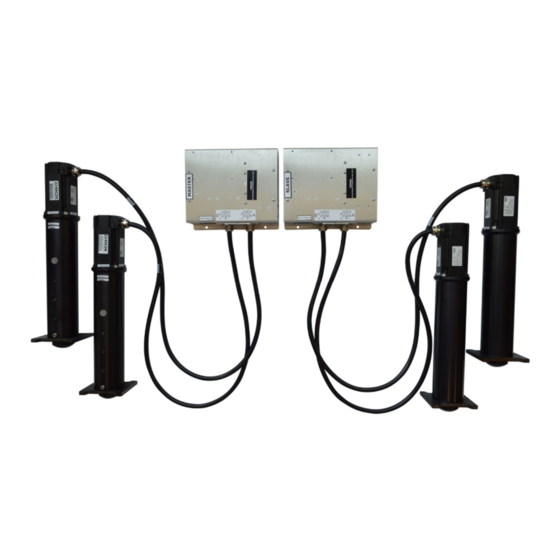
ACM Connections Depending on the ACM position in the system, it is programmed either as: ● MASTER: first ACM in a Motion System ● SLAVE: all following ACMs Here are typical ACM configurations for the connection of a single Motion System:... - Page 12 The following example shows 3 Motion Systems using 2 ACMs each.
-
Page 13: Acm G3 Led Status
Core. The Newton units are a reference to the load perceived by each motor but can’t be converted into actual Newtons. Therefore D-BOX uses the eponym index. Make sure that the weight on the platform is no higher than the maximum supported weight. -
Page 14: Weight Distribution
Each actuator has an individual maximal payload as previously mentioned. When integrating the Motion System on a platform, D-BOX recommends balancing the center of gravity (CG) of the platform to ensure each actuator supports an equal load . The following figures show equal distribution of weight with 2, 3 or 4 actuators. -
Page 15: Actuator Acceleration
Actuator Acceleration The D-BOX Motion System can produce a 1G acceleration or greater. However, to avoid risks of injury for the user or damage to the equipment, D-BOX recommends calibrating the Motion System to produce a maximum of 1G, using the control panel - see information on Motion Core. -
Page 16: Actuator Alignment
alignment Actuator When using 4 actuators, install them per a square or rectangular pattern. Avoid other patterns - e.g. trapezoid. Actuator straightness During installation, the actuators should always remain straight to limit radial loading. Radial loading could result in premature wear of the actuators. Level surface All actuators must be level on the same flat surface for optimal operations. -
Page 17: Motion System Accessories
To select your converter, please follow the power requirement listed in the spec sheets for your specific configuration. Other than power requirement, D-BOX would like to suggest the use of an isolated converter to avoid risks of electrical shock. If a non-isolated converter is selected, please make sure to secure ground connection. -
Page 18: Removal/Installation Procedures
EMOVAL NSTALLATION PROCEDURES H-Bracket for 1.5 in HD Actuator - AC10 Removal 1. Remove bolt (9) and pivot (8). 2. Remove bolt (7) and end piston adapter (6). 3. Remove bolt (5), lockwasher (4), stop (3), and H-plate (2) from housing (1). Installation NOTE : Apply one drop of Loctite 243 blue threadlocker on bolts (5), (7) and (9) before installation. -
Page 19: H-Bracket For 3In Actuator - Ac231
H-Bracket for 3in Actuator - AC231 Removal CAUTION: extend the piston and lock with a wrench to avoid breaking the cam follower. 1. Remove bolt (6) with a 3/8” hex bit, spacer (5) and pivot (4). 2. Remove bolt (3) and H-bracket (2). Installation 1. -
Page 20: H-Bracket For 6In Actuator - Ac360
2. Apply Loctite 243 (blue) thread locker in the four blind holes (2) on the piston body. NOTE : Apply the thread locker just before the bottom of the blind holes. 3. Use a 5 mm bit to secure the H-bracket plate to the piston body with 4 screws (item 4, M6 X 1.0 X 14 mm), then tighten the 4 screws to a torque of 133 N m (98 lbf in). -
Page 21: Captive Ending
Captive ending Some platforms may require the use of an actuator ending that binds the actuator to the floor or a frame. The D-BOX captive ending (ball joint) allows proper actuator movements. The D-BOX captive ending is a 2 components assembly:... - Page 22 Ball joint There are 2 models of ball joints. OEM : use with 6in - AC360 - actuators. OEM LITE : use with 1.5in - AC211, AC10 - and 3in - AC231 actuators. Spacer retainer The spacer-retainer allows specific movements of the ball joint on both x and y axes, thus eliminating any constraints during the movement of the platform.
-
Page 23: 1.5-Inch Actuator - Ac218
To help with positioning, the spacer retainer is marked OUTWARD on its top surface. 1.5-inch actuator - AC218 Here are installation instructions for the D-BOX ball joints. Make sure all the parts are clean before installation. CAUTION: Never operate the AC218 actuator without the pivot installed. Operating the... - Page 24 Removal Unscrew bolt (4) with the ½ hex key and remove washer (3) and pivot (2) from the actuator (1). Apply threadlocker Loctite 263 to the threaded section of bolts (3) and ball joint (4). Install pivot (2) on actuator (1) with bolts (3). Torque bolts to 50 lbf in.
- Page 25 Slide retainers (6) on spacer (5) and in the slot on the ball joint. Align the holes in the retainers with the holes in the spacer. Use 5/16 bolts to tighten the spacer and retainers to the floor. NOTE : the way the ball joint is anchored to the floor is the same for all actuators –...
-
Page 26: 3-Inch Actuator - Ac231
3-inch actuator – AC231 Unscrew bolt (1) with the 3/8 hex key and remove pivot (2) and spacers (3) from the actuator. Unscrew bolt (4) with the 4mm hex key and (optional) remove H-bracket (5) from the actuator. Add Loctite 263 to the threaded section. Screw the threaded section in the actuator (1). - Page 27 3-inch actuator – AC231 Slide retainers (4) on spacer (3) and in the slot on the ball joint. Align the holes in the retainers with the holes in the spacer. Use 5/16 bolts to tighten the spacer and retainers to the floor.
-
Page 28: 6-Inch Actuator - Ac360
6-inch actuator - AC360 Unscrew bolt (1) with the ½ hex key and remove pivot (2) and spacer (3) from actuator (4). Add Loctite 263 to the threaded section. Screw the threaded section in the actuator (1). Use a torque wrench with a 5/8 crow foot socket to tighten the ball joint assembly (2) in the actuator. - Page 29 6-inch actuator - AC360 Slide retainers (4) on spacer (3) and in the slot on the ball joint. Align the holes in the retainers with the holes in the spacer. Use 5/16 bolts to tighten the spacer and retainers to the floor.
-
Page 30: Ac218 Actuator Replacement
AC218 A CTUATOR EPLACEMENT Removal Remove the screws holding the center ACM cover. Then remove the remaining screws from the actuator cover and gently pull the actuator cover from the ACM. Each actuator is identified by a letter. Each actuator has two cables: a power cable and an encoder cable. -
Page 31: Installation
Installation Plug both power and encoder cables in the ACM. Install the actuator cover with screw. Install the center ACM cover with screw.
Need help?
Do you have a question about the G3 and is the answer not in the manual?
Questions and answers