
Related Manuals for HYDAC FILTER SYSTEMS CSM-E


Summary of Contents for HYDAC FILTER SYSTEMS CSM-E
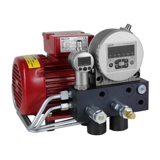
- Page 1 CSM-E ContaminationSensor Module - Economy Installation and Maintenance Instructions English (translation of original instructions) Keep for future reference. Document No.: 3911629a...
-
Page 2: Imprint
These documents have been created and inspected with the greatest care. However, errors cannot be ruled out completely. All details are subject to technical modifications. Technical specifications are subject to change without notice. en(us) CSM-E Page 2 / 64 MoWa CSM-E 3911629a en-us 2017-12-11.docx 2017-12-11... -
Page 3: Table Of Contents
Drilling template for fastening ..............22 Making the hydraulic connections to the unit .......... 23 Installing ContaminationSensor ..............23 Installing additional sensor(s) AS1000 / AS3000 / HLB1400 ..... 25 en(us) CSM-E Page 3 / 64 MoWa CSM-E 3911629a en-us 2017-12-11.docx 2017-12-11... - Page 4 Notes on pipes/hosing ................27 Connecting the IN suction port ............... 28 Hooking up tank connection OUT ............29 Connecting drain port LEAK (with CSM-E 1xxx-2 only…) ...... 29 For the version with the magnetic coupling (CSM-E 1xxx-4…) please note the following: ............... 30 Electrical connection of the unit ..............
-
Page 5: Preface
Warranty For the warranty provided by us, please refer to the terms of delivery of HYDAC FILTER SYSTEMS GMBH. You will find these under www.hydac.com -> Legal information. en(us) CSM-E Page 5 / 64 MoWa CSM-E 3911629a en-us 2017-12-11.docx 2017-12-11... -
Page 6: Using The Documentation
The documentation number with its index enables you to order another copy of the operating and maintenance instructions. The index is incremented by one digit every time the manual is revised or changed. en(us) CSM-E Page 6 / 64 MoWa CSM-E 3911629a en-us 2017-12-11.docx 2017-12-11... -
Page 7: Safety Information
NOTICE NOTICE – The signal word indicates a hazardous situation with a high level of risk, which, if not avoided, will result in damage to property. en(us) CSM-E Page 7 / 64 MoWa CSM-E 3911629a en-us 2017-12-11.docx 2017-12-11... -
Page 8: Structure Of The Safety Information And Instructions
Hazard, general Danger due to electrical voltage / current Risk of burns due to hot surfaces en(us) CSM-E Page 8 / 64 MoWa CSM-E 3911629a en-us 2017-12-11.docx 2017-12-11... -
Page 9: Signs Used For Giving Orders
Read and observe the operation and maintenance instructions. Others used symbols The following symbols found you in this operation instructions. Tip for handling the product Tools required en(us) CSM-E Page 9 / 64 MoWa CSM-E 3911629a en-us 2017-12-11.docx 2017-12-11... -
Page 10: Signs Used For The Required Specialist Personnel
Observe the following regulatory information and guidelines: • Legal and local regulations for accident prevention • Legal and local regulations for environmental protection • Country-specific regulations, organization-specific regulations en(us) CSM-E Page 10 / 64 MoWa CSM-E 3911629a en-us 2017-12-11.docx 2017-12-11... -
Page 11: Proper/Designated Use
Any use extending beyond this or deviating therefrom shall not be considered intended use. HYDAC Filter Systems GmbH will assume no liability for any damage resulting from such use. The user alone shall assume any and all associated risk. - Page 12 ► raffinates. NOTICE Highly contaminated fluid The pump will become worn out / damaged For long-term operation, pump only fluid with a maximum ► contamination of ISO 22/20/18 en(us) CSM-E Page 12 / 64 MoWa CSM-E 3911629a en-us 2017-12-11.docx 2017-12-11...
-
Page 13: Qualifications Of Personnel / Target Group
Such persons with corresponding specialist training and several years' work experience. They are able to assess and perform the work assigned to them, they are also able to recognize potential hazards. en(us) CSM-E Page 13 / 64 MoWa CSM-E 3911629a en-us 2017-12-11.docx 2017-12-11... - Page 14 • Knowledge about contamination due to solids and water Disposal Specialist • Proper and environmentally- personnel friendly disposal of materials and substances • Decontamination of contaminants • Knowledge about reuse en(us) CSM-E Page 14 / 64 MoWa CSM-E 3911629a en-us 2017-12-11.docx 2017-12-11...
-
Page 15: Wear Suitable Clothing
Use a powder extinguisher that corresponds to fire class B as per EN EN 2 to extinguish any fires. Maintain a minimum safe distance from electrical components. For a mains voltage of up to 1000 V, the minimum safe distance is 1 m. en(us) CSM-E Page 15 / 64 MoWa CSM-E 3911629a en-us 2017-12-11.docx 2017-12-11... -
Page 16: Unpacking The Unit
Rinse and drain the unit completely before putting it into extended storage. Store the unit in a clean, dry place. Store the unit on the rubber buffers in an upright position. en(us) CSM-E Page 16 / 64 MoWa CSM-E 3911629a en-us 2017-12-11.docx 2017-12-11... -
Page 17: Decoding The Name Plate
-> Model code; for details, see page 59 Max. INLET press -> Maximum pressure at the inlet section Max. Flow rate -> Maximum flow rate Weight -> Weight when empty en(us) CSM-E Page 17 / 64 MoWa CSM-E 3911629a en-us 2017-12-11.docx 2017-12-11... -
Page 18: Checking The Scope Of Delivery
Do not put the unit into operation. The following items are supplied: Item Designation ContaminationSensor Module, CSM-E Fastening screws for the ContaminationSensor Installation and Maintenance Instructions, this document en(us) CSM-E Page 18 / 64 MoWa CSM-E 3911629a en-us 2017-12-11.docx 2017-12-11... -
Page 19: Characteristics Of The Unit
8% air per bar). This is achieved using a valve situated downstream of the CS. However, pressurized air cannot be immediately dissolved in oil, consequently a path is provided for between the pump and the sensor. en(us) CSM-E Page 19 / 64 MoWa CSM-E 3911629a en-us 2017-12-11.docx 2017-12-11... -
Page 20: Unit Components
Rubber buffer for assembly onto connection block Rubber buffer for assembly onto electric motor Screw plug / Cavity for the AquaSensor AS1000 / AS3000 Flange port for the ContaminationSensor CS1000 en(us) CSM-E Page 20 / 64 MoWa CSM-E 3911629a en-us 2017-12-11.docx 2017-12-11... -
Page 21: Hydraulic Circuit Powerpack
Suction strainer, 400 µm Suction port (IN) Tank connection (OUT) Leakage oil connection (LEAK) (optional) Cavity for the AquaSensor AS1000 / AS3000 Flange port for the ContaminationSensor CS1000 en(us) CSM-E Page 21 / 64 MoWa CSM-E 3911629a en-us 2017-12-11.docx 2017-12-11... -
Page 22: Drilling Template For Fastening
Hydraulic circuit powerpack Drilling template for fastening All dimensions in mm. en(us) CSM-E Page 22 / 64 MoWa CSM-E 3911629a en-us 2017-12-11.docx 2017-12-11... -
Page 23: Making The Hydraulic Connections To The Unit
Before hooking it up hydraulically, assemble the ContaminationSensor CS1000 as follows: Remove the plastic screw plug (24) at the flange port. Use a lint-free cloth to clean the sealing surface at the en(us) CSM-E Page 23 / 64 MoWa CSM-E 3911629a en-us 2017-12-11.docx 2017-12-11... - Page 24 (9). Tighten the fastening screws (9) tight using an Allen wrench = 5 mm (torque: 8 ± 0.5 Nm). Installation of the ContaminationSensors (30) is complete. en(us) CSM-E Page 24 / 64 MoWa CSM-E 3911629a en-us 2017-12-11.docx 2017-12-11...
-
Page 25: Installing Additional Sensor(S) As1000 / As3000 / Hlb1400
Tighten the additional sensor tight using a fork wrench = 27 mm (torque : 20 +2 Nm). The installation of the additional sensor (31) is complete. en(us) CSM-E Page 25 / 64 MoWa CSM-E 3911629a en-us 2017-12-11.docx 2017-12-11... -
Page 26: Overview Of The Hydraulic Connections
Making the hydraulic connections to the unit Overview of the hydraulic connections The following illustration shows the hydraulic connections on the power unit: Suction port connection Return port connection LEAK Leakage oil connection (optional) en(us) CSM-E Page 26 / 64 MoWa CSM-E 3911629a en-us 2017-12-11.docx 2017-12-11... -
Page 27: Notes On Pipes/Hosing
Make sure that no vibrations or stress/loading are carried over to the pump by fastening the tubes. Mount hoses or expansion joints if necessary. en(us) CSM-E Page 27 / 64 MoWa CSM-E 3911629a en-us 2017-12-11.docx 2017-12-11... -
Page 28: Connecting The In Suction Port
The unit will be destroyed Note the maximum pressure on the suction port connection IN ► for CSM-E 1xxx-1 = -0.4 bar to 0.5 bar for CSM-E 1xxx-2 = -0.4 bar to 120 bar for CSM-E 1xxx-4 = -0.4 bar to 80 bar Use a negative pressure-resistant, flexible hose or a pipe for the suction-side connection. -
Page 29: Hooking Up Tank Connection Out
Closed tank connection (OUT) The unit will be destroyed Make sure that the return port is always open ► Connecting drain port LEAK (with CSM-E 1xxx-2 only…) NOTICE Closed drain port (LEAK) The unit will be destroyed Make sure that the leakage oil connection is always open ►... -
Page 30: For The Version With The Magnetic Coupling (Csm-E 1Xxx-4
Making the hydraulic connections to the unit For the version with the magnetic coupling (CSM-E 1xxx-4…) please note the following: The CSM1xx0-4… is equipped with a magnetic coupling between the electric motor and the pump. This magnetic coupling serves as a fuse element. The following needs to be considered when fault-finding. -
Page 31: Electrical Connection Of The Unit
To change the direction of rotation, commutate two phases. Depending on the network voltage, connect the motor in a star or delta connection. Check the type label on the motor to accomplish this. en(us) CSM-E Page 31 / 64 MoWa CSM-E 3911629a en-us 2017-12-11.docx 2017-12-11... -
Page 32: Electrical Connection Of The Contaminationsensor Cs1000
More information on this can be found in the corresponding installation instructions for the product. Electrical connection of the CSI-C-11 (optional) More information on this can be found in the corresponding installation instructions for the product. en(us) CSM-E Page 32 / 64 MoWa CSM-E 3911629a en-us 2017-12-11.docx 2017-12-11... -
Page 33: Starting Up The Unit
The counter balance valve (4) is delivered in a fully opened state. Adjusting the counter balance valve Adjust the counter balance valve (4) according to the following steps. en(us) CSM-E Page 33 / 64 MoWa CSM-E 3911629a en-us 2017-12-11.docx 2017-12-11... -
Page 34: Required Tools
The following tools are needed to set up the counter balance valve: Open-jaw wrench = 13 mm Allen wrench = 4 mm The two following procedures described for setting the counter balance valve are possible. en(us) CSM-E Page 34 / 64 MoWa CSM-E 3911629a en-us 2017-12-11.docx 2017-12-11... -
Page 35: Setting The Counter Balance Valve With A Pressure Gauge
Loosen the screw plug on the right-hand side of the CS in a counterclockwise direction and remove it completely. Screw the gauge port connector (A) into the CS. en(us) CSM-E Page 35 / 64 MoWa CSM-E 3911629a en-us 2017-12-11.docx 2017-12-11... - Page 36 ContaminationSensor (max. 60 bar) Unscrew the cap nut from the counter balance valve. Release the lock nut on the counter balance valve. en(us) CSM-E Page 36 / 64 MoWa CSM-E 3911629a en-us 2017-12-11.docx 2017-12-11...
- Page 37 11. Unscrew the pressure gauge (B) from the gauge port. The gauge port can remain in the 12. The unit is ready for operation. en(us) CSM-E Page 37 / 64 MoWa CSM-E 3911629a en-us 2017-12-11.docx 2017-12-11...
-
Page 38: Setting Up The Counter Balance Valve Without Pressure Gauge
Tighten the lock nut. Make sure that the setting of the counter balance valve is not changed in the process. Screw the head-nut onto the counter balance valve and tighten it firmly. en(us) CSM-E Page 38 / 64 MoWa CSM-E 3911629a en-us 2017-12-11.docx 2017-12-11... - Page 39 Adjusting the counter balance valve The unit is ready for operation. en(us) CSM-E Page 39 / 64 MoWa CSM-E 3911629a en-us 2017-12-11.docx 2017-12-11...
-
Page 40: Mounting Accessories
If you have ordered a montage kit for the power unit, mount it as illustrated in the following. Item Designation Montage Kit CSM-E, consisting of: - 1x assembly sheet for setup or suspension - 1x fastening material (screws, discs, nuts) -
Page 41: Performing Maintenance
24 hrs. 500 hrs. 3000 hrs. daily monthly twice per year Check for leaks Visual check of electrical equipment Clean the suction strainer en(us) CSM-E Page 41 / 64 MoWa CSM-E 3911629a en-us 2017-12-11.docx 2017-12-11... -
Page 42: Clean The Suction Strainer
1. Open the screw plug with an Allen wrench = 6 mm. 2. Take out the suction strainer by rotating it with a large, flat screwdriver in counterclockwise direction. en(us) CSM-E Page 42 / 64 MoWa CSM-E 3911629a en-us 2017-12-11.docx 2017-12-11... - Page 43 4. Rotate the suction strainer in clockwise direction into the housing with a large, flat screwdriver. 5. Screw in the screw plug by hand and tighten it with 12 Nm. en(us) CSM-E Page 43 / 64 MoWa CSM-E 3911629a en-us 2017-12-11.docx 2017-12-11...
-
Page 44: Errors And Troubleshooting
Suction strainer of the gear Clean the suction pump is clogged. strainer. See page 42. Only CSM-E 1xxx-1 / -2: Contact HYDAC. The coupling between the motor and the pump is loose or faulty. Only CSM-E 1xxx-4: Switch the pump off. -
Page 45: Shutting Down The Unit
See chapter "Taking the unit out of operation" Disposing of the unit After dismantling the unit and separating the various materials, dispose of the unit in an environmentally-friendly manner. en(us) CSM-E Page 45 / 64 MoWa CSM-E 3911629a en-us 2017-12-11.docx 2017-12-11... -
Page 46: Ordering Spare Parts
Ordering spare parts Ordering spare parts Make sure to indicate the entire unit designation and the serial number in accordance with the type label when ordering spare parts. en(us) CSM-E Page 46 / 64 MoWa CSM-E 3911629a en-us 2017-12-11.docx 2017-12-11... - Page 47 Pressure relief valve Pressure relief valve Rubber buffer 606841 Lock washer Washer Rubber buffer 6075352 Screw connection Screw connection Screw connection Screw connection Plug Screw Screw plug 615003 en(us) CSM-E Page 47 / 64 MoWa CSM-E 3911629a en-us 2017-12-11.docx 2017-12-11...
- Page 48 Pipe elbow, assy. Type label Screw plug 613141 Plastic plug with hand lever 6044485 Installation and Maintenance Instructions 3911629 *) available on request, -) not deliverable as spare part en(us) CSM-E Page 48 / 64 MoWa CSM-E 3911629a en-us 2017-12-11.docx 2017-12-11...
-
Page 49: Ordering Accessories
AquaSensor AS3008-5-000 922591 HLB14J8-1C000-000 923684 HLB14J8-00S12-000 923685 SensorMonitoring Unit 3467005 SMU1260-TU-00 SensorMonitoring Unit 3791708 SMU1261-TU-00 SensorMonitoring Unit 3704282 SMU1270-TU-00 SensorMonitoring Unit 3805688 SMU1271-TU-00 Pressure gauge Kit 0-60 bar 3942792 en(us) CSM-E Page 49 / 64 MoWa CSM-E 3911629a en-us 2017-12-11.docx 2017-12-11... - Page 50 CD FluMoT driver package 3355177 ContaminationSensor 3249563 Interface CSI-D-5 ContaminationSensor Interface CSI-C-11 4066011 CSI-V-11-0-0-0/-000 Power supply unit, PS5 3399939 Connection cable, screened, with 5-pole elbow 6019455 female connector, open en(us) CSM-E Page 50 / 64 MoWa CSM-E 3911629a en-us 2017-12-11.docx 2017-12-11...
- Page 51 2 m (ZBE42S-02) Connection cable, shielded with 8-pin mating connector 3281239 <-> 8-pin open end length 5 m (ZBE42S-05) Connection cable, shielded 3346101 with 4-pin mating connector <-> RJ45 en(us) CSM-E Page 51 / 64 MoWa CSM-E 3911629a en-us 2017-12-11.docx 2017-12-11...
- Page 52 Connection cable, shielded with 4-pin mating connector 3346101 <-> RJ45, length 10 m (ZBE45-10) Socket plug, 5-pin with 6006786 screw clamp (ZBE08) Socket plug, 8-pin with 3281243 screw clamp (ZBE44) en(us) CSM-E Page 52 / 64 MoWa CSM-E 3911629a en-us 2017-12-11.docx 2017-12-11...
-
Page 53: Technical Data
CSM-E1xxx-2 Permissible operating viscosity range CSM-E1xxx-4 2 … 1000 mm²/s CSM-E1xxx-1 10 … 1000 mm²/s CSM-E1xxx-2 Permissible viscosity range for the measurement operation CSM-E1xxx-4 2 … 800 mm²/s en(us) CSM-E Page 53 / 64 MoWa CSM-E 3911629a en-us 2017-12-11.docx 2017-12-11... - Page 54 Technical Data en(us) CSM-E Page 54 / 64 MoWa CSM-E 3911629a en-us 2017-12-11.docx 2017-12-11...
- Page 55 Rotational speed 1425 rpm 1755 rpm IP class IP55 IP55 Insulation class For other electrical versions, obtain the respective data from the type label on the electric motor. en(us) CSM-E Page 55 / 64 MoWa CSM-E 3911629a en-us 2017-12-11.docx 2017-12-11...
-
Page 56: Appendix
HYDAC SERVICE GMBH Friedrichsthaler Straße 15a, Werk 13 66540 Neunkirchen-Heinitz Germany Telephone: +49 681 509 441 Fax: +49 681 509 324 E-mail: service@hydac.com en(us) CSM-E Page 56 / 64 MoWa CSM-E 3911629a en-us 2017-12-11.docx 2017-12-11... -
Page 57: Unit Dimensions
Unit dimensions The powerpack has different dimensions depending on how it is equipped with sensors and interface modules. Dimensions with CS1000, AS1000 and CSI-C11 All dimensions in mm. en(us) CSM-E Page 57 / 64 MoWa CSM-E 3911629a en-us 2017-12-11.docx 2017-12-11... -
Page 58: Dimensions With Cs1000, Hlb1400 And Csi-C11
Appendix Dimensions with CS1000, HLB1400 and CSI-C11 All dimensions in mm. en(us) CSM-E Page 58 / 64 MoWa CSM-E 3911629a en-us 2017-12-11.docx 2017-12-11... -
Page 59: Model Code
230 V, 50 Hz, 3 Ph / 265 V, 60 Hz, 3 Ph 400 V, 50 Hz, 3 Ph / 460 V 60 Hz, 3 Ph Supplementary details = without en(us) CSM-E Page 59 / 64 MoWa CSM-E 3911629a en-us 2017-12-11.docx 2017-12-11... -
Page 60: Explanation Of Terms And Abbreviations
Fluoroelastomer rubber FluMoS FluidMonitoring Software FluMoT FluidMonitoring driver package HYDACLab Sensor Inlet INLET Inlet LEAK Leakage oil connection Nitrile rubber Outlet OUTLET Outlet PowerSupply SensorMonitoring Unit Electronics accessories en(us) CSM-E Page 60 / 64 MoWa CSM-E 3911629a en-us 2017-12-11.docx 2017-12-11... -
Page 61: Index
OUT 20, 21, 26, 29, 30, 33, 36, 38, 53, 60 OUTLET 60 DIN 60 Sensor 60 Error 44 Transport 14, 16 Filter 11 FluMoS 50, 60 FluMoT 50, 60 en(us) CSM-E Page 61 / 64 MoWa CSM-E 3911629a en-us 2017-12-11.docx 2017-12-11... - Page 64 HYDAC FILTER SYSTEMS GMBH Industriegebiet Postfach 1251 66280 Sulzbach/Saar 66273 Sulzbach/Saar Germany Germany Tel: +49 6897 509 01 Central Fax: +49 6897 509 9046 Technology Fax: +49 6897 509 577 Sales Department Internet: www.hydac.com E-mail: filtersystems@hydac.com...
Need help?
Do you have a question about the CSM-E and is the answer not in the manual?
Questions and answers