Table of Contents
Advertisement
Quick Links
Advertisement
Table of Contents

Related Manuals for Scientific SME1190


Summary of Contents for Scientific SME1190
- Page 1 AC/DC HIPOT TESTER SME1190/SME1190A User Manual...
- Page 2 Information in this manual supercede all corresponding previous released material. Scientific continues to improve products and reserves rights to amend part or all of the specifications , procedures, equipment at any time without notice.
-
Page 3: Table Of Contents
Content Chapter 1 Overview ............................ 5 1.1 Introduction .................................5 1.2 Conditions of Use ..............................6 .................................... 6 1.2.1 Power 1.2.2 Ambient Temperature and Humidity ............................6 1.2.3 Preheating ..................................6 1.2.4 Precautions ..................................6 1.3 Volume and Weight .............................7 1.4 Safety Requirements ............................7 1.4.1 Insulation Resistance ................................ - Page 4 4.6 Voltage Breakdown Test ........................... 37 4.6.1 Brief description ................................37 Operation instruction ..............................37 4.6.2 4.7 File Storage................................ 39 4.8 HANDLER ................................ 40 4.8.1 Brief Introduction ................................40 4.8.2 External Control Line Legend ............................. 41 Chapter 5 Interface and Communication ....................45 5.1 Remote Control Interface ..........................
-
Page 5: Chapter 1 Overview
High Voltage Floating Output design (for SME1190 only) When SME1190 high voltage output is set to the floating state, if the output high voltage is 5KV AC or 6KVDC at high voltage output terminal HV1, HV2, the leakage current of HV1 or HV2 terminal to earth(Earth) is no more than 3mA. -
Page 6: Conditions Of Use
USB DEVICE interface and LAN interface HANDLER interface: this interface enable the connection of the tester and the automatic equipment, control the tester operation and feedback the test results. GPIB interface (option): this general purpose interface provides the convenience for the tester to be connected with an automatic test system including a computer and other measuring instruments This tester also provides convenient and practical file function, which can save the measuring... -
Page 7: Volume And Weight
Do not use the tester in locations near a sensitive measuring instrument or receiver. Operation in a location subject, may cause such equipment may be affected by noise generated by the tester. At a test voltage exceeding 3 kV, corona discharge may be generated to produce substantial amounts of RF broadband emissions between grips on the test lead wire. -
Page 8: Chapter 2 Precautions On Handling
Chapter 2 Precautions on Handling This chapter describes the precautions to be followed in the handling of this tester. When using the tester, take utmost care to ensure safety. ! WARNING: The tester derives a 5 KVAC or 6KVDC test high voltage, incorrect or wrong operation can cause accidents which will result in human injury or death. - Page 9 high voltage is remote controlled, the operator can not know the actual working state of the tester through the interface. Please pay special attention to the reliability of remote control connection: 「 「 「 「 STOP」 」 」 」 key, must be connected reliably, 「 STOP」 key must be pressed before changing the DUT.
-
Page 10: Handling Measures
C: capacitance of the DUT If the time constant of the DUT is known, then the time required to discharge to 30V can be calculated by the above formula after the output is cut off. 8) Turn ON or OFF the Power Switch Once the power switch is turned off, be sure to allow several seconds or more before turning it ON again, never turn on and off the power switch repeatedly, so as not to cause erroneous actions. - Page 11 Warning: Keep away from the instrument after turning off the power and prevent other people from approaching. Do not immediately disassemble the test circuit. Immediately call our distributor or agent. High voltage may remain in the interior of the instrument. It is hazardous for an unqualified person to attempt to troubleshoot any tester problem.
-
Page 12: Chapter 3 Panel Description
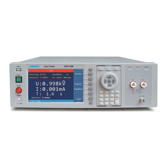
Chapter 3 Panel Description The contents of this chapter are only for a brief description. For details of operation and detailed explanation, refer to Chapter 4 for the corresponding content. 3.1 Front Panel Figure 3-1 gives a brief description of the front panel. Figure 3-1 1. -
Page 13: Rear Panel
DANGER light is on, it means there is high voltage delivering, touching is forbidden. 13. HV2 Terminal RTN terminal of high voltage output (only for SME1190, when GFI is set to FLOAT), when DANGER light is on, it means there is high voltage delivering, touching is forbidden. - Page 14 DANGER light is on, it means high voltage is delivering, touching is forbidden. 2. HV1 Terminal The high potential terminal of high voltage output, this is the high voltage output terminal, when DANGER light is on, it means there is high voltage delivering, touching is forbidden. 3.
-
Page 15: Chapter 4 Basic Operation
Chapter 4 Basic operation 4.1 Interface structure overview The following figure is the interface structure: TEST TEST TEST TEST S S S S tart Test tart Test tart Test tart Test SETUP SETUP STEP: : : : 01 STEP 01/01 I I I I nsert Delet nsert Delete e e e Save Save... -
Page 16: System Setup
4.2 SYSTEM Setup 4.2.1 System Test Parameter Settings Operation Instructions: 1. Press 〖SYSTEM〗key to enter the system setting interface shown in Figure 4-2. 2. Press F1~F3 key to change the measurement, environment and interface related system settings. 3. Press〖▲〗,〖▼〗 key to move the cursor to the parameters you want to set. Change the parameter settings with F1~F6 keys or numeric keys. - Page 17 Setup items Range Default Explanation Manual Set the trigger mode of the instrument to start the Trg. Mode External Manual test, only accept the trigger signal in the current trigger mode. Set the delay time from the receipt of the trigger Trg.
- Page 18 Before the completion of one measurement, the tester ignores other triggers. It can only be triggered again after the measurement is finished, or press the【STOP】key to exit the current measurement, and then trigger the measurement again. Manual trigger: press the【START】key on the panel to start measuring. External trigger: input a low level greater than 10mS through the external HANDLER interface board.
- Page 19 Figure 4-3 4.2.1.4 Auto Range When the auto range, that is, the withstand voltage auto range function is set to ON, at 0.6S before the completion of the test, if the measured current can be expressed by the low current range, the current range is automatically changed to the low current range.
- Page 20 The electric shock protection setting has three options, namely OFF, ON and FLOAT (only SME1190 has high-voltage floating output function). OFF and ON means the function is turned off and on. FLOAT means that the two high voltage output HV1 (high end), HV2 (low end) are isolated from the earth (with very high insulation resistance), for details, see the floating part description below.
-
Page 21: System Environment Parameters Setting
b) When the electric shock protection is set to FLOAT, the high-voltage output high terminal HV1, low terminal HV2 are in a float state, as shown in Figure 4-6. When the human body accidentally touches the test high voltage terminal, the low terminal HV2 of the high voltage circuit is not grounded ,but isolated from the ground, equivalent to connecting a high insulation resistance, therefore, the current through the human body will not exceed 3 mA, thus ensuring the safety of operator. - Page 22 Figure 4-8 system environment parameter settings Item Range Default Explanation Key Vol ON/OFF Set the key sound volume to ON or OFF. Language Chinese/English Chinese Set Chinese or English Display. Beep Vol Off/Low/Mid/High High Adjust the buzzer volume. Set the key lock, manual setting or bus UnLock Manual/Bus Manual...
-
Page 23: System Communication Setup
Figure 4-9 key lock and password interface 4.2.3 System Communication Setup Operation Instructions: 1. Press 〖SYSTEM〗 to enter the system setting interface shown in Figure 4-2. 2. Press the 〖F3〗 button to enter the communication settings page. 3. Press 〖▼〗 to move the cursor to the port format setting and enter the setting page shown in Figure 4-10. -
Page 24: Meas Setup
4.3 Meas SETUP Operation Instructions: 1. Press 〖SETUP〗 to enter the measurement setup interface shown in Figure 4-11. 2. INSERT, DELETE, NEW, SAVE or select up or down by pressing the F1~F6. 3. Press the right arrow key to move the cursor to the test mode option, as shown in Figure 4-12, uses the F1~F5 keys to select whether the test mode is AC withstand voltage, DC withstand voltage, insulation resistance, pause mode or open short circuit detection OSC. -
Page 25: Ac Withstanding Voltage Test Mode
4.3.1 AC Withstanding Voltage Test Mode Figure 4-12 Meas Mode Setup Setting Item Range Default Explanation 0.050 ~ 5.000kV, Set the voltage required for AC MeasVolt CLOSE 0 — CLOSE withstanding voltage testing. Select frequency Ac Freq 50Hz or 60Hz 50Hz withstanding voltage testing. -
Page 26: Dc Withstanding Voltage Test Mode
The time it takes to drop from the set voltage to the low voltage. 0.1~999.0s, FallTime CLOSE CLOSE means that the test time is 0 — CLOSE finished and the voltage output is cut off directly. Table 4-3 4.3.2 DC Withstanding Voltage Test Mode Figure 4-13 DC Withstanding Voltage Setup Setting item Range... - Page 27 When the RampJudg is set to ON, the DC withstand voltage testing judges whether the current test value exceeds the set value of current high limit when performing the ramp time. RampJudg CLOSE or ON CLOSE When the RampJudg is set to Close, the DC withstand voltage testing does not judge whether the current test value exceeds the set value of current high limit when...
-
Page 28: Insulation Resistance Test Mode
4.3.3 Insulation Resistance Test Mode Figure 4-14 IR Test Setup Setting item Range Default Explanation 0.050~5.000kV, Set the voltage required for the insulation MeasVolt CLOSE resistance test. 0 —CLOSE Lowlimit 0.1M~50GΩ 1.000MΩ Set the insulation resistance low limit. Set the high limit of the insulation resistance, Low limit~50GΩ, Hi Limit CLOSE... -
Page 29: Pause Mode
MeasRang: Select the appropriate current range for IR, calculate the current value according to the test voltage and the insulation impedance of the DUT, ie I = U/R, and then select the appropriate current range accordingly. Relationship between the current range and resistance measurement range is shown in table 4-6. -
Page 30: Osc Detection Mode Setup
4.3.5 OSC Detection Mode Setup Figure 4-16 OSC Detection Setup Set Up Range Default Explanations Set the conditions for judging the test 10%~100%, result of open, expressed as a percentage Open of the test value and the sampling standard Stepping 1% value. -
Page 31: Test Setup
Figure4-17 Sampling Setup 4.4 TEST Setup Operation Instructions: 1. Press 〖TEST〗 to enter the AC Test interface as shown in Figure 4-18.1. 2. Press F1 to offset. Press F3 and F4 key to display the main parameters of different test steps as shown in Figure 4-18.2, Figure 4-18.3, Figure 4-18.4 and Figure 4-18.5. - Page 32 Figure 4-18.1 AC Test Interface Figure 4-18.2 DC Test Interface Figure 4-18. 3 IR Test Interface 32 | 8 4...
-
Page 33: 1Offset
Figure 4-18.4 OSC Test Interface Figure 4-18.5 PAUSE Mode Interface 4.4.1OFFSET Before testing, due to the change of working environment and position of the test cable, there may be some base numbers when the tester is in no-load test. For some customers who pursuing accurate measurement can conduct offset in TEST interface. -
Page 34: Test Methods
Figure 4-19 STEP Display Interface On the STEP display page, in addition to test steps, test mode information, there is also large font shows the set voltage and current high limit before starting the test. After pressing 【START】 to start the test, the first line of the large font shows the test value of output voltage, the second line shows the actual measured value of the current, and the third line is time. -
Page 35: Sampling Operation Of Standard Capacitor
4. DANGER light stops flashing after the end of offset. 4.5.2 Sampling Operation of Standard Capacitor 1. Before Open Short-Circuit check mode (OSC) testing or testing a new capacitor DUT or replacing a capacitor DUT, the standard capacitance value must be sampled first, or input a capacitor value as the standard value. - Page 36 If the test value is detected abnormal, it is judged as fail and immediately cuts off the output. The rear panel gives a fail signal and the buzzer operates simultaneous, and it will continue until the 【STOP】 key is pressed. The test result in the lower right corner displays FAIL. Explanation Table for Fail: Displayed Test Result Meaning...
-
Page 37: Voltage Breakdown Test
In any case, if you want to abort the test output, just press the 【STOP】 key. The capacitance value displayed by the tester is not the actual capacitance value, but the value of the sampled current after impedance conversion, which should be approximate to the actual capacitance value installed between the test terminals. - Page 38 Figure 4-22 Figure 4-23 Parameters Function Explanation: Item Range Default Explanation Select to step according to the test Step Mode Norm Step/Volt Step Norm step or test voltage. Only for the NormStep mode, set the STEP 2~999 voltage rise steps. Only for the VoltStep mode, set the Step Volt 0.005kV...
-
Page 39: File Storage
AC:0~High Limit Value CLOSE Low Limit DC:0~High Limit Value Set the low limit of leakage current. CLOSE 0—CLOSE AC:0~20mA CLOSE Arc Limit Set the high limit of Arc. DC:0~10mA CLOSE 0—CLOSE Set whether to continue the test when CONT ON/OFF all the setup steps are completed. -
Page 40: Handler
Function Explanation Create a new file. Save Save the currently loaded file. Load Load the file as the current file. Copy All Copy all files for batch processing. Copy Copy internal files to U disk, copy U disk files to internal. Delete Delete the current file. -
Page 41: External Control Line Legend
The output is LOW when the test result is PASS, at this time /PASS /HIGH, /LOW, /ARC_FAIL, /GFI_FAIL and /SHORT_FAIL signal will not have output (all are HIGH). /HIGH Test result is HIGH FAIL, the output is LOW. /LOW Test result is LOW FAIL, the output is LOW. /SHORT_F Test result is SHORT_FAIL, the output is LOW. - Page 42 Take the External Power Supply as an Example 42 | 8 4...
- Page 43 43 | 8 4...
- Page 44 Timing Diagram Timing Diagram——Take 2 test steps as an example Time Range Explanations >10mS Internal trigger signal(/EXT_STRAT) continue time, need about >10mS External trigger signal(/EXT_STRAT) time needed from start to /EOT signal <20mS is cleared, <20mS ----------- Time setup for the trigger delay ----------- Time needed for each test steps (STEP) >10mS...
-
Page 45: Chapter 5 Interface And Communication
Chapter 5 Interface and Communication The instrument can use RS232C serial interface (standard) or GPIB parallel interface (optional) for data communication and remote control without instrument panel, but they can not be used at the same time. They have the same programming commands but use different hardware configurations and telecommunication protocols. - Page 46 DTR (4) DSR (6) (2) RXD RXD (2) Computer (3) TXD SME1190 (Controller) TXD (3) (5) GND GND (5) RTS (7) CTS (8) As can be seen from the above figure, the pin definition of this tester is the same as that of the 9-core connector serial interface pin used by the IMB AT compatible machine.
- Page 47 When communicating with the computer through the serial port, you should first set up the bus mode of the tester. The operation sequence is as follows: Press the SYSTEM menu button → (F3 soft key) → direction key to move the cursor to the port format →...
- Page 48 8) Once the host generates the query, please ensure that all query results are read (once NL is received, meaning end) to avoid the conflict between the query and the loopback; similarly, the host should also read all loopback characters before reading the query result. 9) For some bus commands that take a long time to complete, such as offset, the host should actively wait for, or respond to the user's keyboard input confirmation to synchronize the execution of the previous command, to avoid the next command being ignored or errored...
- Page 49 { char c; int m,n; while( check_stat(PORT) & 256 ) read_port( PORT );/* read data until null */ for( ;*ps; ) { c = 0; for( m = 100;m;m-- ) { send_port( PORT,*ps ); for( n = 1000;n;n-- ) { delay( 2 ); /* wait about 2ms, use dos.h libray funtion */ if( kbhit() &&...
- Page 50 *ps = c; ps++; *ps = 0; /* send a character to serial port */ void send_port( int port,char c ) union REGS r; r.x.dx = port; /* serial port */ r.h.ah = 1; /* int14 function1:send character */ r.h.al = c; /* character to be sent */ int86( 0x14,&r,&r );...
-
Page 51: Gpib Interface Instruction
{ union REGS r; r.x.dx = port; /* serial port */ r.h.ah = 0; /* int14 function0:initial serial port */ r.h.al = code; /* initialization code */ int86( 0x14,&r,&r ); 5.1.2 GPIB Interface Instruction 5.1.2.1 GPIB BUS The IEEE488 (GPIB) universal parallel bus interface is an internationally accepted intelligent instrument bus interface standard. - Page 52 Figure5-1 GPIB Connector/Pin Structure Diagram GPIB Cable Connection Method #1: Tester Back Connector 52 | 8 4...
- Page 53 Figure5-2 Double Back Connector Staking GPIB Cable Connection Method #2: Figure 5-3 Four-Back Connector Stacking 5.1.2.2 GPIB Interface Function This tester provides most of the general functions of GPIB except the controller, see the following table: Code Function Support all data source contact functions Support all digital panel meter contact functions Basic talk function;...
-
Page 54: Serial Port Commands Instruction
the non-volatile memory. The address setting is as below. Press SYSTEM menu key → (F3 soft key) → direction key to move the cursor to port format → GPIB soft key→ direction key to move the cursor to the address number → numeric keypad input address. -
Page 55: Scpi Commands
5.2.1 SCPI Commands Subsystem commands of SME1190/9110A: ●DISPlay ●FUNCtion ●SYSTem ●MMEM ●FETC 5.2.2 DISPlay Subsystem Commands DISPlay subsystem commands are mainly used to set the instrument display page. The :DISPlay? query returns to the current page. DISPlay: : : : PAGE Command Syntax: DISPlay:PAGE <page name>... - Page 56 5.2.3.3 AC Setup Fuction Commands FUNC:SOURce:STEP:AC:VOLT To set / inquiry about the voltage for ACW test. --Syntax: Command message: FUNC:SOUR:STEP <sn>:AC:VOLT<voltage> Query message: FUNC:SOUR:STEP <sn>:AC:VOLT? --Data<sn>: Data format: integer Data range: 1~50 Data accuracy: 1 --Data<voltage>: Data format: integer Data range: 50~5000 Data accuracy: 1 Data unit: V --Example:...
- Page 57 Command message: FUNC:SOUR:STEP <sn>:AC:LOWC<current> Query message: FUNC:SOUR:STEP <sn>:AC:LOWC? --Data<current>: Data format: float Data range: 0~UPPER current (0 is OFF) Data accuracy: 0.001mA Data unit: mA --Example: Set the LOWER current for ACW test in STEP1 as 1mA. Command message: FUNC:SOUR:STEP 1:AC:LOWC 1 Query message: FUNC:SOUR:STEP 1:AC:LOWC? Return message: 1.000 FUNC:SOURce:STEP:AC:TTIM...
- Page 58 Set the RISE time for ACW test in STEP1 as 1s. Command message: FUNC:SOUR:STEP 1:AC:RTIM 1 Query message: FUNC:SOUR:STEP 1:AC:RTIM? Return message: 1.0 FUNC:SOURce:STEP:AC:FTIM To set /inquiry about the FALL time for ACW test. --Syntax: Command message: FUNC:SOUR:STEP <sn>:AC:FTIM<time> Query message: FUNC:SOUR:STEP <sn>:AC:FTIM? --Data<time>: Data format: float...
- Page 59 FUNC:SOUR:STEP <sn>:AC:FREQ? --Data<frequency>: Data format: character Data range: 50/60 Data unit: Hz --Example: Set the test frequency for ACW test in STEP1 as 50Hz. Command message: FUNC:SOUR:STEP 1:AC:FREQ:50 Query message: FUNC:SOUR:STEP 1:AC:FREQ? Return message: 50 5.2.3.4 Commands for DC Setup Function FUNC:SOURce:STEP:DC:VOLT To set /inquiry about the voltage for DCW test.
- Page 60 --Example: Set the upper current for DCW test in STEP1 to 1mA Command message: FUNC:SOUR:STEP 1:DC:UPPC 1 Query message: FUNC:SOUR:STEP 1:DC:UPPC? Return value: 1.000 FUNC:SOURce:STEP:DC:LOWC To set /inquiry about the LOWER current for DCW test. --Syntax: Command message: FUNC:SOUR:STEP <sn>:DC:LOWC<current> Queery message:FUNC:SOUR:STEP <sn>:DC:LOWC? --Data<current>: Data format: float...
- Page 61 --Example: Set the rise time for DCW test in STEP1 to 1s Command message: FUNC:SOUR:STEP 1:DC:RTIM 1 Query message: FUNC:SOUR:STEP 1:DC:RTIM? Return value: FUNC:SOURce:STEP:DC:FTIM To set /inquiry about the FALL time for DCW test. -Syntax: Command message: FUNC:SOUR:STEP <sn>:DC:FTIM<time> Query message: FUNC:SOUR:STEP <sn>:DC:FTIM? --Data<time>: Data format: float Data range: 0~999.0s...
- Page 62 Data range: 0, 1.0~10.0mA (0 is OFF) Data accuracy: 0.1mA Data unit: mA --Example: Set the ARC upper current for DCW test in STEP1 to1mA Command message: FUNC:SOUR:STEP 1:DC:ARC 1 Query message: FUNC:SOUR:STEP 1:DC:ARC? Return value: 1.0 FUNC:SOURce:STEP:DC:RAMPARC To set /inquiry about the RAMP ARC for DCW test. --Syntax: Command message: FUNC:SOUR:STEP <sn>:DC:RAMPARC<current>...
- Page 63 5.2.3.5 Commands for IR Setup Function FUNC:SOURce:STEP:IR:VOLT To set /inquiry about the voltage for IR test. --Syntax: Command message: FUNC:SOUR:STEP <sn>:IR:VOLT<voltage > Query message: FUNC:SOUR:STEP <sn>:IR:VOLT? --Data<voltage>: Data format: float Data range: 50~1000 Data accuracy: 1 Data unit: V --Example: Set the voltage for IR test in STEP1 to 1000V.
- Page 64 Command message: FUNC:SOUR:STEP 1:IR:LOWR 1 Query message: FUNC:SOUR:STEP 1:IR:LOWR? Return value: FUNC:SOURce:STEP:IR:TTIM To set /inquiry about the TEST time for IR test. --Syntax: Command message: FUNC:SOUR:STEP <sn>:IR:TTIM<time> Query message: FUNC:SOUR:STEP <sn>:IR:TTIM? --Data<time>: Data format: float Data range: 0, 0.3~999.0s (0 is OFF) Data accuracy: 0.1s Data unit: s --Example:...
- Page 65 Set the fall time for IR test in STEP1 to 1s. Command message: FUNC:SOUR:STEP 1:IR:FTIM 1 Query message: FUNC:SOURce:STEP:IR:RANG To set /inquiry about the range for IR test. --Syntax: Command message:FUNC:SOUR:STEP <sn>:IR:RANG<range> Query message:FUNC:SOUR:STEP <sn>:IR:RANG? --Data<range>: Data format: integer Data range: 0~6 (0 is AUTO, 1 is 10mA, 2 is 3mA, 3 is 300uA, 4 is 30uA, 5 is 3uA, 6 is 300nA) --Example: Set the range for IR test in STEP1 to10mA.
- Page 66 Query message: FUNC:SOUR:STEP 1: PA:TIME? Return value: 5.2.3.7 Commands for OSC Setup Function FUNC:SOURce:STEP:OS:OPEN To set /inquiry about the OPEN rate for OS test. --Syntax: Command message: FUNC:SOUR:STEP <sn>:OS:OPEN<rate> Query message: FUNC:SOUR:STEP <sn>:OS:OPEN? --Data<rate>: Data format: integer Data range: 10~100 Data accuracy: 10 Data unit: --Example:...
- Page 67 The instrument will automatically sample the standard capacitance value after impedance transformation of the current. FUNC:SOURce:STEP:OS:STAND To set /inquiry about the STANDARD capacitance for OS test. --Syntax: Command message: FUNC:SOUR:STEP <sn>:OS:STAND<standard capacitance > Query message: FUNC:SOUR:STEP <sn>:OS: STAND? --Data< standard capacitance >: Data format: float Data range: 0.001~40.000 Data accuracy: 0.001...
- Page 68 --Example: Set the step for breakdown test:55 Command message: FUNC: :BREAK: STEP 55 Query message: FUNC: :BREAK: STEP? Return value: FUNC:BREAKdown:STEPVOLT To set /inquiry about the STEP VOLTAGE for voltage breakdown test . --Syntax: Command message: FUNC:BREAK:STEOVOLT<step voltage > Query message: FUNC: :BREAK: STEOVOLT? --Data<step voltage >: Data format: float Data range: 5~500...
- Page 69 Data unit: V --Example: Set the starting voltage for breakdown test to 1000V. Command message: FUNC:BREAK:VOLTS 1000 Query message: FUNC:BREAK:VOLTS? Return value: 1000 FUNC:BREAKdown:VOLTEnd To set /inquiry about the VOLTAGE END for voltage breakdown test. --Syntax: Command message: FUNC:BREAK:VOLTE<voltage> Query message: FUNC: :BREAK:VOLTE? --Data<voltage>: Data format: float Data range: 50~5000...
- Page 70 --Data<current>: Data format: float Data range: 0~uppder current (0 is OFF) Data accuracy: 0.0001mA (DC); 0.001mA (AC) Data unit: mA --Example: Set the lower current for breakdown test to1mA. Command message: FUNC:BREAK:LOWC 1 Query message: FUNC:BREAK:LOWC? Return value: 1.000 FUNC: BREAKdown:TTIM To set /inquiry about the TEST TIME for voltage breakdown test.
- Page 71 --Syntax: Command message:FUNC:BREAK:WTIM<time> Query message: FUNC:BREAK:WTIM? --Data<time>: Data format: float Data range: 0~999.0s (0 is OFF) Data accuracy: 0.1s Data unit: s --Example: Set the waiting time for breakdown test to1s. Command message: FUNC:BREAK:WTIM 1 Query message: FUNC:BREAK:WTIM? Return value: FUNC:BREAK:ARC To set /inquiry about the ARC high current for voltage breakdown test.
-
Page 72: System Subsystem Commands
--Example: Save the setting for breakdown test Command message: FUNC:BREAK: SAVE 5.2.4 SYSTem Subsystem Commands 5.2.4.1 Commands for MEA Setup Function SYSTem:MEA:TRGMODE To set /inquiry about the TRIGGER MODE for test. --Syntax: Command message: SYSTem:MEA:TRGMODE<mode> Query message: SYSTem:MEA:TRGMODE ? --Data<mode>: Data format: characters Data range: 0~3 (0: manual, 1:external, 2:bus, 3:auto) --Example:... - Page 73 --Example: Set the measurement mode to normal. Command message: SYSTem:MEA:MEAMODE 0 Query message: SYSTem:MEA:MEAMODE ? Return value: 0 SYSTem:MEA:RPTCNT To set /inquiry about the REPEAT COUNT for test. --Syntax: Command message: SYSTem:MEA:RPTCNT<count > Query message: SYSTem:MEA:RPTCNT ? -Data<count>: Data format: integer Data range: 0~999 Data accuracy: 1 --Example:...
- Page 74 Command message: SYSTem:MEA:AFTERFAIL 0 Query message: SYSTem:MEA:AFTERFAIL ? Return value: 0 SYSTem:MEA:PASSHOLD To set /inquiry about the beep response time for PASS HOLD. --Syntax: Command message: SYSTem:MEA:PASSHOLD <time> Query message: SYSTem:MEA:PASSHOLD ? --Data<time>: Data format: float Data rang: 0.2~99.9s Data accuracy: 0.1s Data unit: s --Example: Set the pass hold beep response time to1.0s.
- Page 75 Query message: SYSTem:MEA:HARDAGC? Return value: ON SYSTem:MEA:SOFTAGC To set /inquiry about SOFTWARE COMPENSATION status. --Syntax: Command message: SYSTem:MEA:SOFTAGC <ON/OFF>or<1/0> Query message: SYSTem:MEA:SOFTAGC? --Data<ON/OFF>: Data format: characters Data range: OFF (0), ON (1) --Example: Set the software compensation to ON. Command message: SYSTem:MEA:SOFTAGC ON Query message: SYSTem:MEA:SOFTAGC? Return value: SYSTem:MEA:AUTORANGE...
- Page 76 5.2.4.2 Commands for ENV Setup Function SYSTem:ENV:KEYVOL To set /inquiry about the state for KEY VOLUME. --Syntax: Command message: SYSTem:ENV:KEYVOL <ON/OFF>or<1/0> Query message: SYSTem:ENV:KEYVOL? --Data<ON/OFF>: Dataformat: characters Data range: OFF (0), ON (1) --Example: Set the key sound volume state to ON. Command message: SYSTem:ENV:KEYVOL 1 Query message: SYSTem:ENV:KEYVOL? Return value: 1...
- Page 77 Command message: SYSTem:ENV:FAILVOL <ON/OFF>or<1/0> Query messa: SYSTem:ENV:FAILVOL? --Data<ON/OFF>: Data format: characters Data range: OFF (0), ON (1) --Example: Set fail volume to ON. Command message: SYSTem:ENV:FAILVOL 1 Query message: SYSTem:ENV:FAILVOL? Return value: 1 SYSTem:ENV:LANGuage To set /inquiry about the state for LANGUAGE. --Syntax: Command message: SYSTem:ENV:LANGuage <1/0>...
-
Page 78: Mmem Subsystem Commands
Command message: SYSTem:ENV:BRIght <brightness> Query message: SYSTem:ENV:BRIght? --Data<brightness>: Data format: integer Data range: 1~10 --Example: Set the backlight brightness to 5. Command message: SYSTem:ENV:BRIght 5 Query message: SYSTem:ENV:BRIght? Return value: 5 SYSTem:ENV:DATE To set /inquiry about the system DATE. --Syntax: Command message: SYSTem:ENV:DATE <year month date>... -
Page 79: Usb Subsystem Commands
--Example: Set save file name: SME1190TEST Command message: MMEM:SAVE SME1190TEST MMEM:LOAD LOAD the internal file specified by the file name to the current. --Syntax: Command message: MMEM:LOAD <file> --Data<file>: Data format: characters --Example: Set the load file name to SME1190TEST. Command message: MMEM:LOAD SME1190TEST Return value: load pass return OK, load fail return ERROR MMEM:DEL... -
Page 80: Fetch Subsystem Commands
USB:LOAD LOAD current settings to external storage file name. --Syntax: Command message: USB:LOAD <file name> --Data<file name>: Data format: characters --Example: Set the load file name to SME1190TEST. Command message: USB:LOAD SME1190TEST Return value: load pas return OK, load fail return ERROR USB:DEL DELETE current settings to external storage file name. -
Page 81: Other Commands
Inquiry about the model and version information of the instrument. Return message: <manufacturer>,<model>,<firmware><NL^END> Where, <manufacturer> Gets the manufacturer name (Tonghui) <model> Gets the machine model (such as SME1190/9110A) <firmware> Gets the version number of firmware (such as Version1.0.5) For example: *IDN? FUNC:START Start Test... -
Page 82: Chapter 6 Technical Parameter
Chapter 6 Technical Parameter Model SME1190 SME1190A Withstanding Voltage Test Range 0.05-5.0kV Waveform 50/60Hz ±0.1% Sinusoidal Wave Output 500VA (5.0kV 100mA) Output Voltage Power Range 0.05-6.0kV Output 150VA (6.0kV 25mA) Power Load Regulation ± (1%set value + 0.2%full scale) (rated power) - Page 83 OSC Detection Sampling Standard Capacitance Range 0.001~40nF Open Circuit Judgement Range 10%~100% Short Circuit Judgement Range 100%~500% Time Setting Test Time 0.3~999s, 0 indicates continuous testing Rise Time 0.1~999s, 0 is OFF Fall Time 0.1~999s, 0 is OFF Wait Time 0.1~999s, 0 is OFF (on DC withstanding voltage) Safety Protection Function Test Mode...
-
Page 84: Chapter 7 Warranty
Chapter 7 Warranty Scientific warrants all its Instruments to be free from defects in material and workmanship when used under normal operating conditions in accordance with the instructions given in the manual for a period of 12 (Twelve) months from date of purchase from Scientific or its authorized dealers. The service during the warranty period will be rendered on return to factory / service center basis.
Need help?
Do you have a question about the SME1190 and is the answer not in the manual?
Questions and answers