Table of Contents
Advertisement
Quick Links
Advertisement
Table of Contents

Related Manuals for C&D Technologies Liberty MSE


Summary of Contents for C&D Technologies Liberty MSE
- Page 1 ® ® RS02109/0814/CD w w w.cdtechno.com...
- Page 2 Blue Bell, PA 19422-0858 Telephone 1-800-543-8630 +1 (215)619-2700 FAX 215-619-7899 customersvc@cdtechno.com Check C&D’s web site for further details www.cdtechno.com NOTE This manual is to be used for the installation and operating of C&D’s Liberty MSE or Liberty DCS series of batteries. RS02109/0814/CD www.cdtechno.com...
-
Page 3: Table Of Contents
Liberty 2V (Liberty MSE & Liberty DCS) VALVE REGULATED LEAD-ACID BATTERIES TECHNICAL MANUAL Table of Contents Part 1 - Introduction ..........................5 1.1 Cell Characteristics........................5 Part 2 - Recommended Technical References ................. 6 Part 3 - Safety Precautions ......................... 7 3.1 Recommended Tools ........................ - Page 4 Appendix A – Installation of Modules ....................24 Appendix B - Terminal Connections ....................30 Appendix C – MSDS 14-355 Liberty MSE & Liberty DCS ............... 31 Appendix D – Handling and Replacement of Individual Cells ............31 Appendix E – Battery Inspection Report ..................33 Appendix F –...
-
Page 5: Part 1 - Introduction
Part 1 - Introduction The Liberty 2V batteries (Liberty MSE or Liberty DCS) referenced in this document are stationary, lead-acid batteries. They are constructed with an absorbent glass mat (AGM) and are characterized as Valve Regulated Lead-Acid (VRLA). As VRLA, there is no free flowing electrolyte. They are constructed... -
Page 6: Part 2 - Recommended Technical References
Part 2 - Recommended Technical References These instructions assume a certain level of competence by the installer/user. Installers must have the appropriate knowledge and experience to safely install the batteries. The design of the battery room, system wiring, protection, environmental, fire, and safety requirements must comply with applicable codes required by the governing enforcement agency. -
Page 7: Part 3 - Safety Precautions
Part 3 - Safety Precautions This battery is designed for industrial, stationary use only and is not intended for application in vehicular, starting, lighting and ignition (SLI), and the operation of portable tools and appliances. Use in accordance with this manual or all IEEE battery procedures. Use of this product other than in accordance with these instructions may produce hazardous and unsafe operating conditions, leading to damage of equipment and/or personal injury. -
Page 8: Installation Equipment, Tools And Supplies
3.3 Installation Equipment, Tools and Supplies • Lifting sling or appropriately sized platform – for lifting cells into modules or modules into position. • Fork lift or portable crane. • Insulated steel toed safety shoes & remove all metals, i.e. rings, etc – to ensure no short circuits. •... -
Page 9: Part 5 Storage
Part 5 Storage 5.1 Storage Conditions Store batteries indoors in a cool, well ventilated, clean, dry location and place in service as soon as possible after receiving. 5.2 Storage Temperature and Duration The recommended temperature for storage is 50°F (10°C) to 77°F (25°C). Liberty 2V cells may be stored at these temperatures for approximately six months;... - Page 10 When considering room layouts and determining the necessary floor space required for mounting a given system the below diagram is a guide to C&D’s recommended system clearances. Should a question or concern arise please contact your C&D sales representative for further details. Each system is shipped with an Applications Engineering System layout which goes into further detail on system layouts and floor anchoring.
-
Page 11: Ventilation
6.2 Ventilation Although the Liberty 2V batteries are valve regulated, they can produce minimal gas emissions during normal operation. If exposed to abnormal high voltage charging, the cells may vent potentially explosive hydrogen gas. Hydrogen gas when accumulated in a confined area that exceeds four (4%) percent by volume in air is explosive. -
Page 12: Terminal Plates
6.6 Terminal Plates (If part of the battery system) For reasons of safety, it is recommended that terminal plates be installed before connector installation as described in section 6.8. Interconnect cells and modules with tin-plated (standard) copper connectors and 6mm stainless steel hex head bolts and washers in accordance with the connection diagram supplied with each battery shipment. -
Page 13: Tap Connections
The top row of connectors is to be installed first, then the second row down and so on, working from the top down. When installing connectors, install the top (upper most) bolt first. Complete connector installation by torquing all connections to 110 in-lb. [12.4 N-m], using an insulated torque-wrench. NOTE: Over-torquing can damage the post seal and degrade connection integrity. -
Page 14: Part 7 - Initial Charging
Part 7 - Initial Charging General Information and Precautions To safely charge the Liberty 2V batteries and avoid damaging the battery and/or connected equipment, observe the following: • Use a constant voltage charger with only direct current (DC). AC ripple current from charger shall not exceed (5%) of the 8-hour (ampere-hour) rating of the battery. -
Page 15: Initial Charge
Voltage Type Charging Current 77°F (25°C) (25°C) Time Amps per 100Ah Hours battery rating Liberty MSE 2.25 to 2.30 2.35 +/- 0.02 12 – 16 Recommended 2.35 to 2.40 Liberty DCS 2.25 to 2.30 2.4 to 2.45 12 – 24 +/- 0.02... - Page 16 Battery identifications 1. Date of readings 2. Battery total float voltage 3. Ambient operating temperature 4. Date and description of initial or last equalizing charge 5. General observations from visual inspection 6. Individual cell voltages 7. Connection resistance measurement 9. *Optional: One of the following for cell ohmic testers: Impedance, Conductance or Resistance 10.
-
Page 17: Part 8 - Battery Operation
Standby batteries are connected to control circuits, which must be energized at all times. Liberty MSE 2V batteries must be constant voltage charged as described in section 7. Connected to a load in parallel with a continuously operating power supply, these batteries assure instantaneous support of the load in the event of a power failure or brownout. -
Page 18: Equalize Or Freshening Charging
8.3 Equalize or Freshening Charging 8.3.1 Equalize or Freshening Charge Float Charge Applications Under normal float charge operating conditions, it is not necessary to equalize or freshen the Liberty 2V batteries when used within the criteria described in sections 5.2 and 7. NOTE: Some hydrogen gas may be liberated at equalize charging voltage. -
Page 19: Temperature Effects On Batteries
8.4 Temperature Effects on Batteries C&D recommends that the battery be operated at 77°F (25°C) ± 10°F (5.5°C). For ambient temperatures outside the recommended temperature range, the float voltage must be adjusted by 2mV per °F or 3.6mV per °C. Adjust as indicated below. Add 2mV (0.002 volts) per °F or 3.6mV per °C below 77°F (25°C). -
Page 20: Part 9 - Maintenance
Part 9 – Maintenance 9.1 Monthly Inspection The Liberty 2V battery is a VRLA cell which does not require water addition and no specific gravities or water levels need to be checked throughout its life. However, it is recommended to properly follow the below maintenance procedure, to assure that the batteries are well maintained and ready for operation when needed. -
Page 21: Performance Tests
10.2 Float versus Cycle Life Standby batteries such as the Liberty MSE are designed and constructed to provide long life in continuous float service. They differ in their design from the 2V Liberty DCS cycling batteries. Standby... -
Page 22: Low Float Voltage And Sulfation
Liberty DCS cells are specifically designed for cycle service and while their robust design allows them to be used in numerous types of cycle applications from mild shallow DoD service to continuous PSoC service, battery service life can be maximized by following recommended cycle charge voltages and currents as shown in Table 1 (Section 7.1). -
Page 23: Parallel Battery Strings
10.5 Open Circuit – Late Installations As soon as a battery is disconnected from a charger, local action (self-discharge) begins. This is caused by inherent internal losses within the cell. In the case of Liberty 2V cells, a self-discharge is expected to occur at a rate of “up to 3.0 percent”... -
Page 24: Appendix
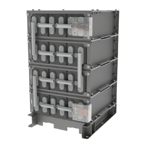
Appendix Appendix A – Installation of Modules The Liberty 2V battery systems can be shipped with the cells installed into the modules or separately. Modules with cells installed are stacked vertically and bolted to pallets for ease of transportation (See Figure A1 & A2). - Page 25 Floor Anchoring Floor loading and anchoring requirements are the responsibility of the user/installer and all applicable building codes and regulations must be followed. C&D provides connection drawings, weights, dimensions, and floor loading information on our system drawings for reference which is supplied with every shipment. Anchor bolts are the responsibility of the user/installer and are not supplied with the order.
- Page 26 Module Stacking/System Assembly With base properly installed, modules unpackaged and in the horizontal position, locate the C&D issued system diagram to verify proper cell orientation when stacking modules. C&D recommends the following two methods for handling Liberty 2V modules. 1. Portable Crane/Fork lift: In the case of limited access in the rear of the module install only the (4) 10mm bolts in the rear flanges prior to hoisting.
- Page 27 Module Stacking/System Assembly (Tiers 2 and higher) 1. Using either of the two lifting methods described on the previous sheet continue with stacking modules for tiers (2) on up. As mentioned before it is always a good practice to reference C&D connection diagram while stacking modules to assure proper cell orientation.
- Page 28 System Restraints All systems are supplied from the factory with two types of restraints. These restraints are critical in maintaining the seismic rating of the system and must be installed properly. Front Restraint Front restraints are installed between each tier of the system to prevent cells from shifting in the event of an earthquake.
- Page 29 Stack Module Disassembly and Re-assembly Procedure If a requirement to disassemble and re-assemble a module stack arises, follow the following procedure. 1. Starting with the uppermost module in the stack, remove the individual cells following the instructions shown in Appendix D. 2.
-
Page 30: Appendix B - Terminal Connections
Appendix B - Terminal Connections 1. Remove any remaining factory-applied grease coating from the terminals with a dry cloth. 2. Lightly brush the terminal, cable lug, terminal plates and contact surfaces with a plastic brush or burlap. 3. Coat all electrical surfaces with NO-OX-ID grease. (Optional: Use heat gun or hot plate to melt and then apply the NO-OX-ID grease, no open flames). -
Page 31: Appendix C - Msds 14-355 Liberty Mse & Liberty Dcs
Appendix C – MSDS Documentation For the most up to date MSDS information, please visit the C&D Technologies public website. Public Website - www.cdtechno.com MSDS Sheets - http://cdtechno.com/resource/msds.html RS02109/0814/CD www.cdtechno.com... -
Page 32: Appendix D - Handling And Replacement Of Individual Cells
Appendix D – Handling and Replacement of Individual Cells A key design feature of the Liberty 2V battery is the provision for servicing individual cells. With a minimum amount of handling and downtime, individual cells can be changed in the field. In addition, disassembly and re- assembly of the stack modules may accommodate installation of a new battery if necessitated by a hard-to-access location. -
Page 33: Appendix E - Battery Inspection Report
Appendix E – Battery Inspection Report RS-1992 APPENDIX E BATTERY INSPECTION REPORT TECHNICAL SERVICE DEPARTMENT Inspection by: 1400 UNION MEETING ROAD BLUE BELL, PA 19422 Date of Inspection: C&D TECHNOLOGIES' 2-VOLT BATTERY AND CHARGER INSPECTION REPORT User's Name: Authorized Site Contact: Installation Location: Phone Number: Other:... - Page 34 RS-1992 BATTERY CHARGE STATUS Open Circuit Float Equalize BATTERY BUS VOLTAGE LOCATION: Internal Cell Internal Cell Volts Connection Conductance/ Volts Connection Conductance/ Cell # Serial # Cell # Serial # +2.000 Resistance Impedance/ +2.000 Resistance Impedance/ Resistance Resistance RS02109/0814/CD www.cdtechno.com...
-
Page 35: Appendix F - Recycling
Appendix F – Recycling Lead-acid batteries are recyclable and C&D Technologies currently has a low cost, convenient, and environmentally safe collection and recycling program. Visit the C&D Web site at www.cdtechno.com further information. RS02109/0814/CD www.cdtechno.com... - Page 36 RS02109/0814/CD www.cdtechno.com...
- Page 37 RS02109/0814/CD www.cdtechno.com...
- Page 38 Any data, descriptions or specifications presented herein are subject to revision by C&D Technologies, Inc. without notice. While such information is believed to be accurate as indicated herein, C&D Technologies, Inc. makes no warranty and hereby disclaims all warranties, express or implied, with regard to the accuracy or completeness of such information.
Need help?
Do you have a question about the Liberty MSE and is the answer not in the manual?
Questions and answers