Advertisement
Congratulations and thank you for your purchase of the Planet
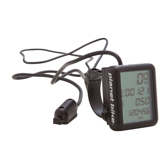
Bike Protegé Bicycle Computer. The Protegé represents a
breakthrough in bicycle computer design and function. The
MacroMonitor™ LCD display, "buttonless" design, and overall
compact size offer advantages to you the cyclist that no other
computer can match. In addition, Planet Bike will donate 25% of
our profits from this purchases and any other Planet Bike
product you buy, to non-profit bicycle advocacy groups to
further benefit your cycling experience. Enjoy your new Protegé
Bicycle Computer and thank you for making a difference!
2. Mounting Instructions
STEP 1:
Attach the wheel sensor to the right or left fork using two quick ties (diagram #1).
Note: Do not fully tighten quick ties until final placement is determined. We recommend a
sensor placement of 1-2 inches up from hub axle (diagram #1). Position sensor and wire on
backside (toward rider) of fork blade to offer protection from debris while riding.Ł
Ł
STEP 2:
Attach magnet to spoke using screwdriver (diagram #2) so magnet lines up
directly across from one of the flat round dots at the lower or upper portion of wheel sensor
with a distance of 1-2 mm between sensor and magnet (diagram #3).Ł
Caution: Do not over-tighten magnet screw.Ł
Ł
STEP 3:
Attach the wire harness to the fork using quick ties (diagram #1). Excess wire can
be wrapped around brake cable before securing bracket to handlebar. Note: Allow slight wire
slack between fork and brake cable for turning handlebars.Ł
Ł
STEP 4:
Attach the computer bracket to the handlebars near the stem (diagram #4). Use
any combination of rubber shims to fit different diameter handlebars. Tighten the screw so
the bracket will not rotate on the handlebars. Slide the computer head into the bracket until it
"snaps" into place.Ł
Ł
STEP 5:
TEST. Install computer head into bracket and rotate front wheel to test for proper
function of magnet/wheel sensor alignment. The mph/kph indicator will flash if the sensor and
magnet are properly aligned. Tighten quick ties on sensor when correct alignment is acheived.Ł
Ł
TO REMOVE COMPUTER HEAD FROM BRACKET: Push the computer in the opposite direction
you would to mount it (diagram #5). The computer head will "snap" out. Note: You may have
to push hard, do not be afraid of breaking it, it will pop out.
3. Functions, Specifications & Additional Features
SCREEN:
1Ł
2
Additional Features:
LINE
: LCD Specification : Line 1, 2 and 3 modes do not change
1Ł
CURRENT SPEED • Miles or Kilometers per hour • 0-99.5 mph/Kph • Increments of 0.5 mph/KphŁ
2Ł
RIDE TIME, "RTM" • Up to 9:59:59 • Increments of 1 secondŁ
3Ł
RIDE DISTANCE, "DST" • Up to 999.99 M or K • Increments of 0.01 M or KŁ
4
ODOMETER, "ODO" • Up to 999.99 M or K • Increments of 0.01 M or K
OR
CHANGE MODE TO SCREEN 2 BY PUSHING COMPUTER FORWARD IN BRACKET TO ACCESS:
CLOCK• 12 Hr Format • Indicated by flashing colon ":"
+ Auto-Start/Stop - Automatically starts recording data or stops recording data when you start or stop ridingŁ
+ Auto LCD Off - LCD automatically shuts off to conserve power after 5 minutes of non-use. Clock will still be displayed.Ł
+ MacroMonitor™ LCD display displays up to 4 functions at once, allowing for fewer mode changes.Ł
+ "Buttonless" design for ease of use - push computer forward in bracket to change modes.Ł
+ Weather proof construction and heavy duty wire harness for all-weather use.
1. Parts List
1
. Mounting Bracket
1 mm
4
2 mm
. Rubber Shims
MOUNTING SENSOR
1
MOUNTING BRACKET
2
. Wheel Sensor
5
. Wheel Magnet
MOUNTING MAGNET (Front Wheel)
2
COMPUTER HEAD REMOVAL
FrontŁ
of bike
4
PUSH AND RELEASE FORŁ
CAUTION:Ł
HOLD FORŁ
LESS THAN ONE SECONDŁ
OR YOU WILL RESET ALLŁ
OF THE RIDE DATA
3
. Computer Case
6
. Quick Ties
Line up SensorŁ
and MagnetŁ
at same levelŁ
Ł
* 1-2 mm apartŁ
Ł
* DO NOT line upŁ
Magnet betweenŁ
flat round dotsŁ
3
on Sensor.
RearŁ
of bike
5
MODE
Ł
CHANGEŁ
Advertisement
Table of Contents

Related Manuals for Planet Bike Protege 5.0


Summary of Contents for Planet Bike Protege 5.0
- Page 1 MacroMonitor™ LCD display, "buttonless" design, and overall compact size offer advantages to you the cyclist that no other computer can match. In addition, Planet Bike will donate 25% of our profits from this purchases and any other Planet Bike 1 mm .
- Page 2 Ł setup data. Replace the computer in the bracket. Ł Ł If you experience any other problems, Contact your Planet Bike dealer or Planet Bike. ©2002. Planet Bike. All Rights Reserved.
Need help?
Do you have a question about the Protege 5.0 and is the answer not in the manual?
Questions and answers