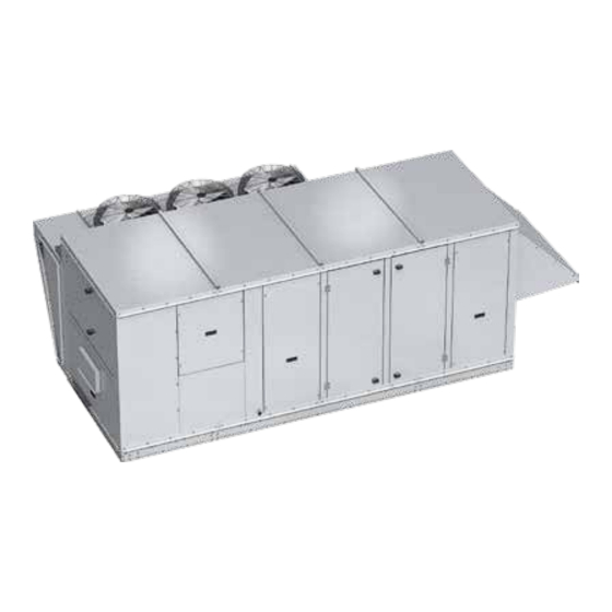
valent VX Series Installation, Operation And Maintenance Manual

valent VX Series Installation, Operation And Maintenance Manual

Dedicated outdoor air unit
Hide thumbs Also See for VX Series:
Table of Contents

Advertisement

Installation, Operation and Maintenance Manual
Please read and save these instructions for future reference. Read carefully before attempting to assemble, install,
operate or maintain the product described. Protect yourself and others by observing all safety information. Failure
to comply with these instructions will result in voiding of the product warranty and may result in personal injury
and/or property damage.

General Safety Information

Only qualified personnel should install and maintain this
system. Personnel should have a clear understanding of
these instructions and should be aware of general safety
precautions. Improper installation can result in electric
shock, possible injury due to coming in contact with
moving parts, as well as other potential hazards. Other
considerations may be required if high winds or seismic
activity are present. If more information is needed,
contact a licensed professional engineer before moving
forward.
1. Follow all local electrical and safety codes, as well
as the National Electrical Code (NEC), the National
Fire Protection Agency (NFPA), where applicable.
Follow the Canadian Electrical Code (CEC) in
Canada.
2. All moving parts must be free to rotate without
striking or rubbing any stationary objects.
3. Unit must be securely and adequately grounded.
4. Do not spin wheel faster than maximum cataloged
Fan Rpm. Adjustments to fan speed significantly
affect motor load. If the fan RPM is changed, the
motor current should be checked to make sure it is
not exceeding the motor nameplate amps.
5. Verify that the power source is compatible with the
equipment.
6. Never open access doors to the unit while it is
running.
Dedicated Outdoor Air Unit
WARNING
The roof lining contains high voltage wiring. To
prevent electrocution, do not puncture the interior or
exterior panels of the roof.
DANGER
• Always disconnect power before working on or near
this equipment. Lock and tag the disconnect switch
or breaker to prevent accidental power up.
• If this unit is equipped with optional gas accessories,
turn off gas supply whenever power is disconnected.
CAUTION
This unit is equipped with a compressed refrigerant
system. If a leak in the system should occur,
immediately evacuate the area. An EPA Certified
Technician must be engaged to make repairs or
corrections. Refrigerant leaks may also cause bodily
harm.
CAUTION
When servicing the unit, the internal components may
be hot enough to cause pain or injury. Allow time for
Cooling before servicing.
Document 483593
Model VX / VXE
Dedicated Outdoor Air Unit
1

Advertisement

Table of Contents
loading
Need help?

Need help?

Do you have a question about the VX Series and is the answer not in the manual?

Questions and answers

Subscribe to Our Youtube Channel

Summary of Contents for valent VX Series

  • Page 1 Document 483593 Model VX / VXE Dedicated Outdoor Air Unit Installation, Operation and Maintenance Manual Please read and save these instructions for future reference. Read carefully before attempting to assemble, install, operate or maintain the product described. Protect yourself and others by observing all safety information. Failure to comply with these instructions will result in voiding of the product warranty and may result in personal injury and/or property damage.
  • Page 2 Table of Contents General Safety Information ..... . 1 Receiving, Handling, Storage ....3 Product Overview .
  • Page 3 Receiving Outdoor The unit should be placed on a level surface to prevent This product may have been subject to road salt during water from leaking into the unit. The unit should be transit. If so, immediately wash off all visible white elevated so that it is above water and snow levels.
  • Page 4 Product Overview A horizontally configured High Percentage Outdoor Air unit designed for installation either indoors or outdoors. Each unit has multiple options for cooling and/or heating. The unit is designed to replace air that is exhausted from the building and also heat and cool, as needed.
  • Page 5 Subassemblies Blower - Supply Filters - Either one or two plenum-type fans. All units All housings are available with a filter are equipped with a plenum fan for Supply Air and a bank depth of either 2 or 4-inch. second may be selected for Exhaust (Relief) Air. Indirect Gas-Fired Furnace - Furnace model PVG is Coils -...
  • Page 6 Installation Typical Unit Weights and Dimensions Component Access Optional Inverter Compressor Optional Compressor/Electrical Optional Gas Furnace/Optional Electric Heater Electrical Supply Blower Coil Filters Exhaust Blower/Optional Electric Preheat * When a powered exhaust fan (or RVE) is selected, door 8 will be to the immediate right of door 7.
  • Page 7 Installation Service Clearances NA from CS CONDENSING SECTION NA from Unit EXHAUST AIR WEATHERHOOD ACCESS DOOR OUTDOOR AIR WEATHERHOOD SUPPLY FAN EXHAUST FAN CONTROL CENTER ACS SIDE Control Cabinet End Outdoor Air Intake from from Piping Indoor Unit Size Access Vestibule from Unit Condensing...
  • Page 8 Installation Handling Concerns for Additional Clearances for Packaged DX or Air-Source Heat Pump Packaged DX Units Units with PDX or ASHP have a system that is Packaged DX units require additional clearance pressurized with refrigerant. If damage occurs, the because they must have unrestricted air movement refrigerant could leak into the atmosphere or cause around the condenser coil and condenser fans.
  • Page 9 Installation Lifting Roof Curb Mounting 1. Ensure that all shipping materials have been Roof curb details, including duct locations and removed from unit. dimensions, are to be found in the roof curb assembly instructions. 2. To assist in determining rigging requirements, weights are provided in the Unit Weights &...
  • Page 10 Installation Optional Piping Vestibule Rail Mounting and Layout If the unit was ordered with the vestibule, the NA (Non- • The units may be installed on rails provided and Access side) clearance dimension must be measured installed by others. Ensure that rails are designed to from the vestibule.
  • Page 11 Recommended Electrical and Gas Supply Entry Locations Manufacturer recommends that electrical service and Optional Gas Piping gas supply be brought into the cabinet through the Units with indirect gas-fired furnaces require field- end wall, as shown below. There are three penetrations supplied and installed gas supply piping.
  • Page 12 Piping Installation Optional Coil Piping Direct Expansion (DX) Coils (Split DX) 1. Piping should be in accordance with accepted Factory-installed cooling and heating components are industry standards. Pipework should be supported mounted in the coil section of the unit. The coil section independently of the coils.
  • Page 13 Electrical Information Determine the Size of Electric Heater WARNING Wiring The roof lining contains high voltage wiring. To prevent An optional electric heater may require a separate electrocution, do not puncture the interior or exterior power supply. The power connection should be made panels of the roof.
  • Page 14 Control Center Components Main Control Center Components Image represents a typical installation for VXE-112 or VXE-212. Components and locations will vary on VXE-311, -352 and VX models. Electrical Cabinet 1. Power distribution block; high voltage supply is terminated here 2. Fuse holders Electrical Cabinet Accessible via control center door 3.
  • Page 15 Component Operation Optional Component Operation Phase Monitor Exhaust Fan VFD Sequence The unit control circuitry includes a phase monitor that Optional Building Static Pressure Sensor: The constantly checks for phase reversal, phase imbalance, exhaust fan is modulated based upon the signal from loss of phase or a power brownout.
  • Page 16 Optional Component Operation Electronically Commutated (EC) Air-Source Heat Pump Condenser Fans with Standard Scroll or IMPORTANT Digital Scroll Compressors Air-source heat pumps are equipped with a defrost The EC condenser fan will cycle to remove ice from the outdoor coil. During modulate up and down to defrost cycles, melted water may drip from the maintain the highest liquid...
  • Page 17 Optional Component Operation Airflow Monitor Hot Gas Reheat Valve Units equipped with a reheat coil IMPORTANT use a three-way valve with actuator For the airflow monitoring device to perform as to control the supply air discharge intended, field calibration is required. Calibration of temperature of the unit during the airflow monitoring device requires an independent dehumidification mode.
  • Page 18 Optional Component Operation Frost Control Rotation Sensor Extremely cold outdoor air temperatures can cause The rotation sensor monitors energy wheel rotation. If moisture condensation and frosting on the energy the wheel should stop rotating, the sensor will close a recovery wheel. Frost control is an optional feature that set of contacts in the unit control center.
  • Page 19 Factory-Installed Refrigeration System Components Packaged DX Cooling with Three Way Hot Gas Reheat and Hot Gas Bypass 1. Compressor 13. Evaporative Coil 2. High Limit Pressure Switch 14. Low Limit Pressure Switch The switch opens when refrigerant pressure The switch is installed on the suction line and increases above the set point in the discharge line.
  • Page 20 Factory-Installed Refrigeration System Components Air-Source Heat Pump with Three Way Hot Gas Reheat Outdoor Airflow Supply Airflow Outdoor Airflow Supply Airflow Dedicated Outdoor Air Unit...
  • Page 21 Factory-Installed Refrigeration System Components 1. Compressor 2. High Limit Pressure Switch The switch opens when refrigerant pressure increases above the set point in the discharge line. A manual reset is then required. 3. Hot Gas Reheat Valve (optional) Units equipped with a reheat coil use a three- way valve with actuator to control the supply air discharge temperature of the unit during dehumidification mode.
  • Page 22 Start-Up Unit DANGER WARNING Electric shock hazard. Can cause injury or death. Prior to starting up the unit, power must be energized Before attempting to perform any service or for 24 hours without a call for cool to allow the maintenance, turn the electrical power to unit to OFF compressor crankcase heaters time to boil off any at disconnect switch(es).
  • Page 23 Start-Up Unit Pre-Start-Up Checklist IG Furnace o If there is an indirect gas-fired furnace in this unit, o Remove any foreign objects that are located in the refer to the manual provided with this unit for Pre- unit. Start-Up information. o Check all fasteners, set-screws, and locking collars o Gas piping is complete and gas lines are purged.
  • Page 24 Start-Up Checklist - General Start-Up Checklist - General Line Voltage. Check at unit disconnect. L1-L2 Volts L2-L3 Volts L1-L3 Volts Motor Amp Draw Supply Motor 1 Amps Amps Amps Amps Supply Motor 2 Amps Amps Amps Amps Supply Motor 3 Amps Amps Amps Amps...
  • Page 25 Start-Up Checklist - Packaged Direct Expansion (PDX) Start-Up Checklist - Packaged Direct Expansion (DX) Compressor 1 Compressor 2 Compressor 3 Compressor 4 Amps Amps Amps Amps Amps Amps Amps Amps Amps Amps Amps Amps Crankcase Heater Amps Amps Amps Amps Not present on inverter compressor Superheat (Models VX/VXE-112, -212, and -311)
  • Page 26 Start-Up Checklist - Air-Source Heat Pump (ASHP) Compressor 1 Compressor 2 Compressors Amps Amps Amps Amps Amps Amps Crankcase Heater Amps Cooling Superheat Should be between 10º and 20ºF (0% reheat) or Deg. F Deg. F should be between 10º and 30ºF (100% reheat) Subcooling Should be between 10º...
  • Page 27 Start-Up Components Supply/Exhaust Fan The fan should be checked for free rotation. If any The optional exhaust fan is a direct-drive plenum type. binding occurs, check for concealed damage and Fan speed is controlled by a VFD which, in turn, is foreign objects in the fan housing.
  • Page 28 Start-Up Components Communication Setup Airflow Monitoring 1. Press the UP and DOWN keys at the same time for For additional information on how to navigate through 3 seconds the airflow controller menus, refer to technical manuals from GreenTrol® Automation Inc. at www.greentrol. 2.
  • Page 29 Start-Up Components Optional Hot Gas Bypass Valve Optional Dirty Filter Switch (standard scroll) To adjust the switch, the unit must be running with To adjust, connect a pressure gauge to the suction line all of the access doors in place, except for the and block the entering air to the evaporator coil.
  • Page 30 Optional Energy Wheel Start-Up Sequence of Operation If selected, the energy wheel is installed in the unit’s Optional Economizer - The economizer will be locked airstream with one half of the wheel in the intake out when: the outside air is below economizer lockout; airstream and one half in the exhaust airstream.
  • Page 31 Optional Energy Wheel Maintenance Whenever retaining clips are opened, they should be closed as soon as possible. If the wheel should rotate WARNING when a clip is open, the clip will jam against the bearing Whenever performing maintenance or inspections, support bar and could cause damage.
  • Page 32 – Optional Energy Wheel Troubleshooting Symptom Possible Cause Corrective Action Refer to Adjust the Air Seals in the Optional Energy Wheel Air seals are too tight. Energy wheel Start-Up section. does NOT Broken belt. Replace. turn No power to wheel motor. Make sure wheel drive is plugged in.
  • Page 33 Troubleshooting – Unit Symptom Possible Cause Corrective Action Blown fuse or open circuit breaker. Replace fuse or reset circuit breaker and check amps. Defective motor or capacitor. Replace. Blower fails Motor overloaded. Reset VFD and check amps. to operate Check for On/Off switches. Check for correct supply Electrical.
  • Page 34 Troubleshooting – Refrigeration Circuit TROUBLESHOOTING NOTE IMPORTANT Do not release refrigerant to the atmosphere! If required service procedures include the adding or Before any components are changed on the removing of refrigerant, the service technician must refrigeration system, the cause of the failure must be comply with all federal, state and local laws.
  • Page 35 Troubleshooting – Refrigeration Circuit Symptom Possible Cause Corrective Action Refrigerant overcharge. Check pressures, charge by subcooling. Compressor Condenser fan motor defective. Check fan motor. starts but cuts out Condenser coil inlet obstructed or dirty. Check coil and clearances. Clean coil if necessary. on high Check high side equalized pressures, check expansion pressure...
  • Page 36 Troubleshooting – Refrigeration Circuit Symptom Possible Cause Corrective Action Check for high entering wet bulb temperature, check for Excessive load on evaporator coil. excessive air flow. Compressor is unloaded. Check digital scroll controller signal and solenoid valve. (digital scroll) Check the thermal expansion valve, ensure bulb is insulated.
  • Page 37 Troubleshooting – Refrigeration Circuit Symptom Possible Cause Corrective Action Check subcooling, check for leak. Repair leak and add Insufficient refrigerant charge. refrigerant. Defective or improperly adjusted Check superheating and adjust thermal expansion valve. expansion valve. discharge pressure Low suction pressure. See “low suction pressure”.
  • Page 38 Routine Maintenance Annually DANGER It is recommended that the annual inspection and Electric shock hazard. Can cause injury or death. maintenance occur at the start of the cooling season. Before attempting to perform any service or After completing the checklist, follow the unit start-up maintenance, turn the electrical power to the unit to checklist provided in the manual to ensure the OFF at disconnect switch(es).
  • Page 39 Routine Maintenance Maintenance Procedures: For coils with fragile fins or high fin density, foaming chemical sprays and washes are available. Many coil Lubrication - Check all moving components for cleaners use harsh chemicals, so they must be used proper lubrication. Apply lubricant where required. with caution by qualified personnel only.
  • Page 40 Routine Maintenance Outdoor Air Supply Final Model Weatherhood Pre-Wheel Outdoor Exhaust Filters Filters (Aluminum Mesh) (Pre-coil) VX-112 (4) 20x20x2 (4) 20x20 VX-212 (4) 25x25x2 (8) 16x25 VX-311 (6) 20x25x2 (12) 16x20 VX-311 ^ (8) 20x25x2 (12) 16x20 6-row DX coil: VX-352 (4) 20x24 + (4) 20x20 (8) 20x25x1...
  • Page 41 Reference - Venting Connection Locations VXE-112 200-300MBH 100-150MBH COMPRESSOR / CONTROL CENTER COMPRESSOR / CONTROL CENTER ACCESS ACCESS COMBUSTION AIR INLET COMBUSTION AIR INLET EXHAUST OUTLET EXHAUST OUTLET IG FURNACE IG FURNACE ACCESS ACCESS VXE-212 300-400MBH 500MBH COMPRESSOR CONTROL CENTER COMPRESSOR CONTROL CENTER ACCESS...
  • Page 42 Reference - Venting Connection Locations Cont. (Models VX/XVE-352) EXHAUST OUTLET COMBUSTION AIR INLET EXHAUST OUTLET COMBUSTION AIR INLET IG Venting Location Inlet Dimensions Outlet Dimensions Furnace Model Size Edge Length Height Length Height (MBH) Thickness 6 13.8 17.2 20.5 50 NA NA NA NA NA 21.5 6 13.8 24.7 20.5 49.8...
  • Page 43 Reference - Rated Airflow Model Airflow (SCFM) Model Airflow (SCFM) VX-112-5I 2325 VX-212-17.5I 4650 VX-112-5D 2325 VX-212-17.5D 4650 VX-112-5S 2325 VX-212-17.5S 4650 VX-212-17.5A 5500 VX-112-5A 3400 VX-212-20I 4900 VX-112-7.5I 2300 VX-212-20D 5100 VX-112-7.5D 2300 VX-212-20S 5100 VX-112-7.5S 2300 VX-212-20A 6400 VX-112-7.5A 3000 VX-212-25I...
  • Page 44 M E C H A N I C A L A N D C O N T R O L S M A N U A L S Go to the literature section of your air handler's web site to find current mechanical and controls manuals: Valent units: www.valentair.com Dedicated Outdoor Air Model VX/VXE Manual Part number: 483693 Rev.
  • Page 45 Document 483593 Model VX / VXE Dedicated Outdoor Air Unit Installation, Operation and Maintenance Manual Please read and save these instructions for future reference. Read carefully before attempting to assemble, install, operate or maintain the product described. Protect yourself and others by observing all safety information. Failure to comply with these instructions will result in voiding of the product warranty and may result in personal injury and/or property damage.
  • Page 46 Routine Maintenance Annually DANGER It is recommended that the annual inspection and Electric shock hazard. Can cause injury or death. maintenance occur at the start of the cooling season. Before attempting to perform any service or After completing the checklist, follow the unit start-up maintenance, turn the electrical power to the unit to checklist provided in the manual to ensure the OFF at disconnect switch(es).
  • Page 47 Routine Maintenance Maintenance Procedures: For coils with fragile fins or high fin density, foaming chemical sprays and washes are available. Many coil Lubrication - Check all moving components for cleaners use harsh chemicals, so they must be used proper lubrication. Apply lubricant where required. with caution by qualified personnel only.
  • Page 48 Routine Maintenance Outdoor Air Supply Final Model Weatherhood Pre-Wheel Outdoor Exhaust Filters Filters (Aluminum Mesh) (Pre-coil) VX-112 (4) 20x20x2 (4) 20x20 VX-212 (4) 25x25x2 (8) 16x25 VX-311 (6) 20x25x2 (12) 16x20 VX-311 ^ (8) 20x25x2 (12) 16x20 6-row DX coil: VX-352 (4) 20x24 + (4) 20x20 (8) 20x25x1...
  • Page 49 UNISON COMFORT TECHNOLOGIES LIMITED WARRANTY & DISCLAIMER POLICY (Please read the Unison Comfort Technologies terms and conditions of sale Section 9 for additional details, conditions and exclusions.) PRODUCT WARRANTY Unison warrants that at the time of delivery and for a period of twelve (12) months from the initial startup or eighteen (18) months from the date of shipment, whichever is less, its products will be free from defects in materials and manufacture, provided that the products have been installed properly, maintained and operated under normal conditions and serviced in accordance with Unison’s...
  • Page 50 This certificate verifies that Harrison Energy Partners has a Limited Extended Warranty policy from Unison Comfort Technologies for the following unit(s): Unit Brand: Valent Unit Model or Tag#: RVE-85 Unit Serial #: The Extended Limited Warranty coverage for this unit is as follows:...

Table of Contents

Save PDF