Table of Contents
Advertisement
Installation, Operation and Maintenance Manual
Please read and save these instructions for future reference. Read carefully before attempting to assemble, install,
operate or maintain the product described. Protect yourself and others by observing all safety information. Failure
to comply with these instructions will result in voiding of the product warranty and may result in personal injury
and/or property damage.
General Safety Information
Only qualified personnel should install and maintain this
system. Personnel should have a clear understanding of
these instructions and should be aware of general safety
precautions. Improper installation can result in electric
shock, possible injury due to coming in contact with
moving parts, as well as other potential hazards. Other
considerations may be required if high winds or seismic
activity are present. If more information is needed,
contact a licensed professional engineer before moving
forward.
1. Follow all local electrical and safety codes, as well
as the National Electrical Code (NEC), the National
Fire Protection Agency (NFPA), where applicable.
Follow the Canadian Electrical Code (CEC) in
Canada.
2. All moving parts must be free to rotate without
striking or rubbing any stationary objects.
3. Unit must be securely and adequately grounded.
4. Do not spin wheel faster than maximum cataloged
fan RPM. Adjustments to fan speed significantly
affect motor load. If the fan RPM is changed, the
motor current should be checked to make sure it is
not exceeding the motor nameplate amps.
5. Verify that the power source is compatible with the
equipment.
6. Never open access doors to the unit while it is
running.
Dedicated Outdoor Air Unit
WARNING
The roof lining contains high voltage wiring. To
prevent electrocution, do not puncture the interior or
exterior panels of the roof.
DANGER
• Always disconnect power before working on or near
this equipment. Lock and tag the disconnect switch
or breaker to prevent accidental power up.
• If this unit is equipped with optional gas accessories,
turn off gas supply whenever power is disconnected.
CAUTION
This unit is equipped with a compressed refrigerant
system. If a leak in the system should occur,
immediately evacuate the area. An EPA Certified
Technician must be engaged to make repairs or
corrections. Refrigerant leaks may also cause bodily
harm.
CAUTION
When servicing the unit, the internal components may
be hot enough to cause pain or injury. Allow time for
cooling before servicing.
Document 483593
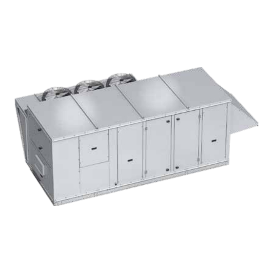
Model VX / VXE
Dedicated Outdoor Air Unit
1
Advertisement
Table of Contents
Troubleshooting

Related Manuals for valent VXE-112


Summarization of Contents
General Safety Information
WARNING: High Voltage
Warning about high voltage wiring in the roof lining.
DANGER: Power Disconnection
Always disconnect power before working on equipment.
CAUTION: Refrigerant System
Precautions for compressed refrigerant system leaks.
CAUTION: Hot Components
Internal components may be hot enough to cause injury.
Unit Receiving and Handling
Receiving and Inspection
Inspect product for damage and verify items upon receipt.
Handling and Unpacking
Use lifting brackets and verify all parts are received.
Unit Storage and Maintenance
Storage Guidelines
Store in a clean, dry environment if not installed.
Inspection and Removal from Storage
Inspect units monthly; check assembly before installation.
Product Overview
Cooling and Heating Options
Available cooling and heating options for the unit.
Airflow Arrangement and Safety
Unit airflow capabilities and safety listings.
Subassemblies Overview
Major Unit Components
Lists and briefly describes key subassemblies like blowers, coils, and compressors.
Installation - Unit Weights and Dimensions
Unit Size and Dimensions Table
Details unit sizes, weights, and overall dimensions.
Component Access Diagram
Shows access locations for various unit components.
Installation - Service Clearances
Required Service Clearances
Table provides required clearances for different unit sizes and access sides.
Installation - Additional Clearances
Clearances for Packaged DX Units
Requires clearance for unrestricted air movement around condenser.
Clearances for Air Source Heat Pump
Requires clearance for unrestricted air movement around outdoor coil.
Handling Concerns
Use protective equipment due to refrigerant hazards.
Installation - Lifting and Mounting
Lifting Procedures and Safety
Guidelines for safely lifting the unit.
Roof Curb Mounting Instructions
Instructions for installing the unit on a roof curb.
Installation - Mounting Options
Optional Piping Vestibule
Clearance measurement considerations for piping vestibule.
Rail Mounting and Layout
Guidelines for installing the unit on provided rails.
Ductwork Configurations
Note on downblast discharge ductwork requirements.
Electrical and Gas Supply Entry
Recommended Entry Locations
Shows typical locations for electrical and gas supply entry.
Alternate Entry Locations
Guidelines for selecting and using alternate entry points.
Gas Piping and Connections
Details gas connection size, pressure, and piping.
Piping Installation
Coil Piping and Water Coils
Notes on coil piping and water coil installation guidelines.
DX Coil and Condensate Drain
DX system piping, drain trap, and overflow switch.
Electrical Information and Safety
Electrical Safety Warnings
Warnings about high voltage, electrocution, and moving parts.
Power Line Sizing and Connections
Sizing power lines and connecting electrical components.
Field-Provided Disconnect
Recommendations for installing a field disconnect switch.
Control Center Components
Main Control Center Layout
Overview of components in Electrical and Controls Cabinets.
Optional Indirect Gas-Fired Furnace
Notes on dual furnace installations and controls.
Component Operation Overview
Phase Monitor and VFD Operation
Monitors phase status and controls blower speed via VFD.
Fan and Damper Control Sequences
How fans and dampers respond to various inputs.
Exhaust Fan and Power
Exhaust fan operation and dedicated power circuit.
Optional Component Operation
EC Fans and ASHP Operation
EC fans modulate; ASHP has defrost and ambient limits.
Operating Conditions and Limitations
Conditions required for cooling and heating modes.
Optional Component Operation
Airflow Monitor and Hot Gas Systems
Airflow monitoring and hot gas bypass/reheat functions.
VFD Compressor and Oil Management
VFD compressor control, envelope, and oil return.
Optional Component Operation
Frost Control Options
Methods to prevent or control energy recovery wheel frosting.
Sensor and Control Systems
Rotation sensor, dirty filter sensor, and microprocessor control.
Factory-Installed Refrigeration Components
Packaged DX Cooling System
Diagram and list for DX cooling with reheat/bypass.
Refrigeration System Components
Lists components like compressor, switches, and valves.
Factory-Installed Refrigeration Components
Air-Source Heat Pump System
Diagram and list for ASHP with reheat.
Refrigeration System Components
Lists components like compressor, reversing valve, EXV/TXV.
Factory-Installed Refrigeration Components
Component List Details
Detailed list of components for ASHP and DX systems.
Start-Up Unit Procedures
Critical Safety Precautions
Essential safety warnings before unit start-up.
Pre-Start-Up Checklist Overview
Key items to verify before energizing the unit.
Start-Up Warnings and Notes
Important warnings and notes for unit start-up.
Start-Up Unit - Pre-Start-Up Checklist
General and Electrical Checks
Verifying fasteners, wiring, controls, and power.
Compressor and Furnace Checks
Checking compressor heaters and gas/water systems.
Start-Up Procedure and Voltage
Steps for unit start-up and voltage imbalance calculation.
Start-Up Checklist - General
Motor Amp Draw and Fan Data
Recording amp draw, RPM, and rotation for fans.
Condensing and Outdoor Fans
Recording amp draw for condenser and outdoor fans.
Compressor Readings
Recording temperatures and humidity for compressors.
Start-Up Checklist - Packaged DX
Compressor Electrical and Refrigerant Data
Recording voltage, amperage, superheat, subcooling, and pressures.
Sight Glass and Bypass Operation
Checking liquid visibility and hot gas bypass.
Start-Up Checklist - Air-Source Heat Pump
Cooling Mode Parameters
Recording cooling superheat, subcooling, pressures, and temperatures.
Heating Mode Parameters
Recording heating superheat, subcooling, pressures, and temperatures.
Start-Up Components
Fan Inspection and Rotation
Checking fan for free rotation and proper rotation direction.
Fan Setup and Vibration
VFD control, motor verification, and vibration causes.
Discharge Air Temperature Sensor
Field installation instructions for the discharge air sensor.
Start-Up Components
Airflow Monitoring Setup
Calibrating and setting up the airflow monitoring device.
Communication Setup
Configuring airflow monitor for MODBUS communication.
Start-Up Components
Dirty Filter Switch Adjustment
Procedures for adjusting the dirty filter switch.
Hot Gas Bypass Valve Adjustment
Steps to adjust the hot gas bypass valve setting.
Optional Energy Wheel
Start-Up and Air Seal Adjustment
Adjusting air seals for minimum leakage and proper operation.
Drive Belt Inspection
Inspecting the drive belt for smooth ride and alignment.
Sequence of Operation
Explains economizer and frost control sequences.
Optional Energy Wheel Maintenance
Inspection and Disassembly
Inspecting wheel, motor, belt; procedures for disassembly.
Cleaning and Reassembly
Procedures for cleaning wheel segments and reassembly.
Belt and Bearing Checks
Inspecting belt and accessing wheel bearing.
Optional Energy Wheel Troubleshooting
Troubleshooting Table
Lists symptoms, causes, and corrective actions for energy wheel issues.
Alarms and Fault Codes
Explains microprocessor and VFD alarm indicators.
Digital Scroll Compressor Fault Codes
Lists fault codes and actions for digital scroll compressors.
Troubleshooting – Unit Issues
Blower and Motor Problems
Diagnosing and fixing blower and motor operational issues.
Airflow Issues
Identifying causes of low or high airflow.
Noise and Vibration Issues
Identifying and resolving noise or vibration problems.
Troubleshooting – Refrigeration Circuit
Compressor Start-Up Failures
Diagnosing and rectifying compressor start-up failures.
Low Pressure Cut-Out Issues
Troubleshooting low pressure cut-out issues.
Troubleshooting – Refrigeration Circuit
High Pressure and Thermal Overload
Diagnosing high pressure and thermal overload cut-outs.
Compressor Noise and Vibration
Identifying causes of compressor noise and vibration.
Troubleshooting – Refrigeration Circuit
High Suction and Discharge Pressure
Diagnosing and resolving high suction/discharge pressure issues.
Low Suction Pressure Issues
Addressing issues leading to low suction pressure.
Troubleshooting – Refrigeration Circuit
Low Discharge Pressure and Short Cycling
Diagnosing low discharge pressure and frequent cycling.
Compressor Oil Loss and Capacity Issues
Identifying causes of oil loss and performance issues.
Frosting Issues
Troubleshooting frosted liquid lines, suction lines, and coils.
Routine Maintenance
Maintenance Frequency Guidelines
Recommended maintenance intervals based on usage.
Monthly Maintenance Tasks
Tasks to perform monthly, including filter cleaning/replacement.
Semiannually Maintenance Tasks
Tasks to perform every six months, like bearing checks.
Annually Maintenance Tasks
Annual inspection items for optimal operation.
Routine Maintenance Procedures
Lubrication, Dampers, and Motors
Procedures for lubricating components and maintaining dampers/motors.
Fan Wheel, Coils, and Filters
Maintaining fan wheels, cleaning coils, and servicing filters.
Reference - Venting Connection Locations
VXE-112 and VXE-212 Venting Details
Diagrams and dimensions for VXE-112 and VXE-212 venting.
IG Venting Locations Table
Table showing IG venting locations and flue connection sizes.
Reference - Venting Connection Locations Cont.
VX/VXE-352 Venting and Dimensions
Diagrams and dimensions for VX/VXE-352 venting.
Reference - Rated Airflow
VX Series Airflow Data
Table listing rated airflow for VX models.
VXE Series Airflow Data
Table listing rated airflow for VXE models.
LIMITED WARRANTY & DISCLAIMER POLICY
PRODUCT WARRANTY
Standard warranty terms for product defects.
START-UP LABOR LIMITED WARRANTY
Limited labor warranty for qualified start-up services.
PARTS-SUPPLIED-BY-OTHERS
Unison's warranty limitations for third-party components.
Extended Limited Warranty Certificate
Warranty Coverage Details
Details warranty extension for various unit components.
Exterior Air Handler Inspection
Shipping Damage, Seams, and Access
Checking for shipping damage, caulking, and door operation.
Ductwork, Drains, and Filters
Checking ductwork, drain systems, and air filters.
Split Air Handler Inspection
Exterior Joints and Mating Surfaces
Inspecting exterior joints, alignment, gasket compression, and bolts.
Reconnections Verification
Verifying wiring and refrigerant/piping reconnections.
Control Cabinet and Power Inspection
Control Cabinet Checks
Checking terminal display, wiring, sensors, and schematics.
Power Inspection
Checking line phasing and comparing measured voltage to nameplate.
Dampers Inspection
Command Matching and Operation
Verifying damper command matching and smooth operation.
Blowers and Blower Motors Inspection
Mechanical Component Checks
Checking fasteners, bearings, belts, and rotation direction.
Motor Overloads and EC Motor Specifics
Setting overloads and checking EC motor inputs/outputs.
VFD Parameters
Recording Modified VFD Settings
Documenting all parameters modified from VFD default settings.
Indirect Fired Gas Furnace
Furnace Identification and Component Inspection
Verifying furnace details and inspecting components.
IDF Furnace Performance Readings
Gas Pressure and Flue Gas Data
Recording gas pressures, CO2, CO, and flue gas temperatures.
Gas Set Point Guidelines
Guidelines for natural gas and propane set points.
Electric Heater Inspection
Electrical and Operational Checks
Verifying electrical integrity and operational parameters.
Integral AC System
Condenser Fan Motor Amp Draw
Recording amp draw for condenser fan motors.
Compressor Readings
Recording voltage and amperage for compressors.
Heat Pump System
Compressor Readings
Recording compressor voltage and amperage for heat pump circuits.
Water Coil Inspection
System Checks and Readings
Verifying valve operation, air, glycol, and recording temperatures.
Energy Recovery Wheel Inspection
System Inspection Checks
Checking cassette, rotor, seals, and drive components.
System Start-Up Checks
Verifying rotor direction, controls, and airflow.
DDC Controller
Serial Number and IO Configuration
Identifying controller serial number and confirming IO configuration.
Wiring and I/O Verification
Checking wiring against schematic and verifying I/O functionality.
DDC Mode of Operation Testing
Mode Verification
Confirming heating, cooling, economizer, defrost, and dehumidification modes.
DDC Parameters
Parameter Settings Recording
Recording default and active parameter settings.
Additional System Notes
System Notes
Space for any additional system notes or observations.
Need help?
Do you have a question about the VXE-112 and is the answer not in the manual?
Questions and answers