Table of Contents
Advertisement
Installation, Operation and Maintenance Manual
Please read and save these instructions for future reference. Read carefully before attempting to assemble, install,
operate or maintain the product described. Protect yourself and others by observing all safety information. Failure
to comply with these instructions will result in voiding of the product warranty and may result in personal injury
and/or property damage.
General Safety Information
Only qualified personnel should install and maintain this
system. Personnel should have a clear understanding of
these instructions and should be aware of general safety
precautions. Improper installation can result in electric
shock, possible injury due to coming in contact with
moving parts, as well as other potential hazards. Other
considerations may be required if high winds or seismic
activity are present. If more information is needed,
contact a licensed professional engineer before moving
forward.
1. Follow all local electrical and safety codes, as well
as the National Electrical Code (NEC), the National
Fire Protection Agency (NFPA), where applicable.
Follow the Canadian Electrical Code (CEC) in
Canada.
2. All moving parts must be free to rotate without
striking or rubbing any stationary objects.
3. Unit must be securely and adequately grounded.
4. Do not spin wheel faster than maximum cataloged
Fan Rpm. Adjustments to fan speed significantly
affect motor load. If the fan RPM is changed, the
motor current should be checked to make sure it is
not exceeding the motor nameplate amps.
5. Verify that the power source is compatible with the
equipment.
6. Never open access doors to the unit while it is
running.
Dedicated Outdoor Air Unit
WARNING
The roof lining contains high voltage wiring. To
prevent electrocution, do not puncture the interior or
exterior panels of the roof.
DANGER
• Always disconnect power before working on or near
this equipment. Lock and tag the disconnect switch
or breaker to prevent accidental power up.
• If this unit is equipped with optional gas accessories,
turn off gas supply whenever power is disconnected.
CAUTION
This unit is equipped with a compressed refrigerant
system. If a leak in the system should occur,
immediately evacuate the area. An EPA Certified
Technician must be engaged to make repairs or
corrections. Refrigerant leaks may also cause bodily
harm.
CAUTION
When servicing the unit, the internal components may
be hot enough to cause pain or injury. Allow time for
Cooling before servicing.
Document 483593
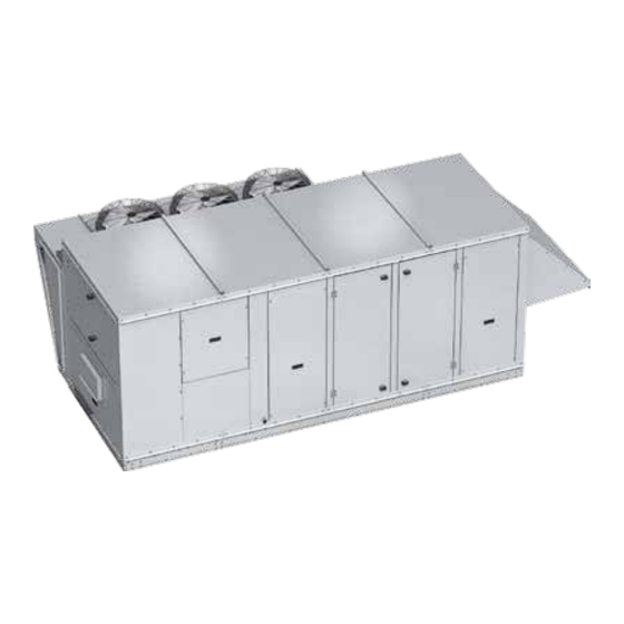
Model VX / VXE
Dedicated Outdoor Air Unit
1
Advertisement
Table of Contents
Troubleshooting

Related Manuals for valent VXE-212


Summarization of Contents
Installation
Typical Unit Weights and Dimensions
Lists unit dimensions, weights, and component access locations.
Service Clearances
Specifies required clearances around the unit for proper installation and maintenance.
Additional Clearances for Packaged DX Units
Details clearance requirements for packaged DX units to ensure proper airflow.
Additional Clearances for Air Source Heat Pump
Specifies clearance needs for ASHP units due to defrost cycle water.
Lifting
Provides instructions and warnings for safely lifting and handling the unit.
Roof Curb Mounting
Details the process for mounting the unit on a roof curb.
Optional Piping Vestibule
Information on clearances required for optional piping vestibules.
Ductwork Configurations
Notes on specific ductwork configurations for downblast discharge.
Recommended Electrical and Gas Supply Entry Locations
Optional Gas Piping
Information on gas connection sizes and pressure for indirect gas-fired furnaces.
Piping Installation
Water Coils
Guidelines for installing and maintaining water coils, including freeze protection.
Direct Expansion (DX) Coils (Split DX)
Instructions for installing DX coils, including piping and condensate drain requirements.
Electrical Information
Determine the Size of the Main Power Lines
Guidance on sizing main power lines based on the unit's nameplate.
Connect the Power Supplies
Instructions for connecting main power lines and electric heater power lines.
Control Center Components
Main Control Center Components
Identifies components within the electrical and controls cabinets.
Component Operation
Phase Monitor
Explains the function of the phase monitor in detecting faults.
Variable Frequency Drive (VFD)
Details how VFDs control blower speed for CAV and VAV systems.
Supply Fan VFD Sequence
Describes how supply fan speed is modulated based on sensor inputs.
Optional Component Operation
Electronically Commutated (EC) Condenser Fans with Standard Scroll or Digital Scroll Compressors
How EC condenser fans modulate speed based on liquid line pressure.
Air-Source Heat Pump
Important considerations for ASHP units, including defrost and snow accumulation.
Optional Component Operation
Airflow Monitor
Details the airflow monitoring system's functionality, calibration, and navigation.
VFD Compressor
Explains VFD compressor operation, envelope control, and oil return management.
Optional Component Operation
Frost Control
Options for preventing or controlling frost on the energy recovery wheel.
Microprocessor Control
How the microprocessor optimizes unit performance and interfaces with BMS.
Factory-Installed Refrigeration System Components
Packaged DX Cooling with Three Way Hot Gas Reheat and Hot Gas Bypass
Diagram and component list for DX cooling with reheat and bypass.
Factory-Installed Refrigeration System Components
Air-Source Heat Pump with Three Way Hot Gas Reheat
Diagram and component list for ASHP with hot gas reheat.
Start-Up Unit
Pre-Start-Up Checklist
Comprehensive checklist for pre-start-up checks covering electrical, compressors, and system types.
Start-Up Unit
Start-Up Procedure
Steps to follow for safely starting up the unit and verifying operation.
Voltage Imbalance
Explains how to identify and the importance of managing voltage imbalance.
Start-Up Checklist - General
Motor Amp Draw
Section to record motor amp draw for various fans and motors.
Compressors
Section to record compressor operating data like temperature and humidity.
Start-Up Components
Fan
Instructions for checking fan rotation, offset, and general condition.
Start-Up Components
Airflow Monitoring
Information on navigating the airflow controller menus and performing field calibration.
Start-Up Components
Optional Dirty Filter Switch
Instructions for adjusting the optional dirty filter switch.
Optional Energy Wheel
Start-Up
Procedures for adjusting air seals and inspecting the energy wheel during start-up.
Sequence of Operation
Explains economizer and frost control sequences for the energy wheel.
Optional Energy Wheel
Maintenance
Guidelines for inspecting, cleaning, and disassembling energy wheel segments.
Optional Energy Wheel – Troubleshooting
Troubleshooting – Alarms
Information on microprocessor controller faults and digital scroll compressor controller fault codes.
Routine Maintenance
Maintenance Frequency
Recommended schedule for performing maintenance tasks (monthly, semiannually, annually).
Monthly
Tasks to be performed on a monthly basis, including filter cleaning and replacement.
Semiannually
Tasks for semiannual maintenance, such as checking motor bearings and coils.
Annually
Annual maintenance checks including lubrication, dampers, and cabinet integrity.
Routine Maintenance
Lubrication
Instructions for lubricating moving components and checking for wear.
Coil Maintenance
Procedures for cleaning evaporator and condenser coils to maintain efficiency.
Internal Filter Maintenance
Guidance on checking and replacing internal pleated paper filters.
CONTACT US / MORE INFORMATION
CONTACT US
Contact information for technical support and service.
MORE INFORMATION
Information on unit schematics and mechanical/controls manuals.
Need help?
Do you have a question about the VXE-212 and is the answer not in the manual?
Questions and answers