Advertisement
Splitband amplifier MSA100
Product description
The amplifier is designed for amplifying SAT IF and terrestrial TV signals.
There are three connectors with DC feeding for external.
22 kHz signal can be passed to SAT IF input from TERR TV + SAT IF output or from 22 kHz control connector, depending
on the possition of 22 kHz path selection switch.
The amplifier has independent switchable gain and slope regulators for SAT IF band and TERR TV band and fixed slope
pre-corrections for both SAT IF and TERR TV bands.
According to the standard ETSI EN 303 354 V.1.1.1, this TERR TV band amplifier type is Launch, selectivity clasification 0.
The amplifier is designed for indoor use only.
Safety instructions
The amplifier is powered from mains 230 V~. This voltage is dangerous to life.
Installation of the amplifiers must be done according IEC60728-11 and national safety standards.
Any repairs must be done by a qualified personnel.
The amplifier is double isolated from the mains 230 V~.
Do not remove the cover of the power supply section, without disconnecting the unit from the mains supply.
Do not plug the amplifier into the mains supply if the power cord or plug is damaged.
Do not plug the amplifier into the mains supply until all cables have been connected correctly.
To disconnect the amplifier completely, disconnect plug from the mains socket.
The mains socket must be easily accessible.
The amplifier shall not be exposed to dripping or splashing water and no objects filled with liquids, such as vases, shall
be placed on it.
Avoid placing amplifier next to central heating components and in areas of high humidity.
No naked flame sources, such as lighted candles, should be placed on amplifier.
If the amplifier has been kept in cold conditions for a long time, keep it in a warm room no less than 2 hours before plugging
into the mains.
Do not insert any objects into ventilation openings.
The ventilation should not be impeded by covering the ventilation openings with items, such as newspapers, table-cloths, curtains.
Mount the amplifier in vertical position with four RF connectors on the left, DC OUT2 and 22kHz connectors underneath.
The amplifier must be fixed with steel screws Ø 4-4.5 mm. The screws are not included in a package.
From top, front and bottom of installed amplifier must be at least 10 cm free space.
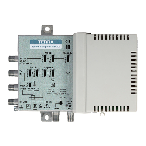
External view and operating controls
Terr.TV input
Terr.TV input
attenuator
equalizer
switches
switches
SAT IF input & DC
output
DC OUT1
Terr.TV input & DC
output
DC OUT 12V (switchable)
Output test
-30 dB
Terr. TV+SAT IF output
Functional
grounding clamp
12 V output switch
12 V output
indicator
SAT IF
input
SAT IF
attenuator
interstage equalizer
switches
switch
22 kHz
DC OUT2
control
output
22 kHz path
DC voltage
selection switch
indicator
Installation
The amplifiers should be mounted vertically with four RF connectors on the left, DC OUT2 and 22 kHz connectors
underneath, in order to ensure good ventilation conditions. Ground the amplifiers housing. Connect the amplifier into the
mains supply lastly.
WARNING!
Overload or short cuircuit on DC OUT1 connector triggers protection of power supply. The amplifier self recovers
when short circuit or overload is eliminated.
Technical characteristics
Frequency range
Gain (fixed slope pre-correction)
Gain adjustment
Slope adjustment
15 dB by 1 dB step
Input and output return loss
Output level
115 dBµV IMD3=60 dB, 2 equal carriers
Noise figure
Output test point
Rejection
DC feeding for external
DC OUT 1
DC OUT 2
DC OUT 12 V
Supply voltage limit values,
power consumption***
Operating temperature range
Dimensions/Weight (packed)
*
short circuit/overload protection is realized on integrated power supply
** has its own short circuit/overload protection
*** with external DC feeding; without external DC feeding 3.7 W
Caution
.
Risk of electric shock.
This product complies with the relevant clauses of the European Directive 2002/96/EC. The unit must be recycled
or discarded according to applicable local and national regulations.
Equipment intended for indoor usage only.
Equipment is double insulated from the mains, with functional earthing.
Functional earthing. Connect to the main potential equalization.
This product is in accordance to following norms of EU: EMC norm EN50083-2, safety norm EN60065, RoHS
norm EN50581.
This product is in accordance with Custom Union Technical Regulations: "Electromagnetic compatibility of technical
equipment" CU TR 020/2011, "On safety of low-voltage equipment" CU TR 004/2011.
This product is in accordance with safety standard AS/NZS 60065 and EMC standards of Australia.
Draugystes str. 22, LT-51256 Kaunas, Lithuania, tel.: +370 37 - 31 34 44, fax: +370 37 - 31 35 55
E-mail: sales@terraelectronics.com, http://www.terraelectronics.com
Terr. TV
SAT IF
47-862 MHz
950-2400 MHz
31-35 dB
35-40 dB
15 dB by 1 dB step
9 dB by 3 dB step
≥
10 dB
120 dBµV IMD3=35 dB, 2 equal carriers
7 dB
8 dB
-30 dB
≥
≥
25 dB of SAT IF
35 dB of Terr. TV
20 V 700 mA*
20 V 100 mA**
12 V 100 mA**, switchable
190-250 V~ 50/60 Hz 29 W
-20
÷ +50
C
0
0
180x135x52 mm/0.62 kg
Advertisement
Table of Contents

Related Manuals for Terra MSA100


Summary of Contents for Terra MSA100
- Page 1 Splitband amplifier MSA100 Installation The amplifiers should be mounted vertically with four RF connectors on the left, DC OUT2 and 22 kHz connectors Product description underneath, in order to ensure good ventilation conditions. Ground the amplifiers housing. Connect the amplifier into the The amplifier is designed for amplifying SAT IF and terrestrial TV signals.
- Page 2 Splitband amplifier MSA100 Installation The amplifiers should be mounted vertically with four RF connectors on the left, DC OUT2 and 22 kHz connectors Product description underneath, in order to ensure good ventilation conditions. Ground the amplifiers housing. Connect the amplifier into the The amplifier is designed for amplifying SAT IF and terrestrial TV signals.
Need help?
Do you have a question about the MSA100 and is the answer not in the manual?
Questions and answers