Advertisement
Quick Links
OPERATING
Settings menu
To enter setting mode, press any keyboard button. The dC
(0V/12V on RF input), F1 (filter1), F2 (filter2), F3 (filter3), F4
(filter4) can be accessed by pressing (▼-minus or ▲- plus) keys.
To enter dC mode, "ENTER" key must be pressed. dC value
(0V/12V) can be set by pressing (▼-minus or ▲- plus) keys.
To confirm the voltage setting "ENTER" must be pressed. The
display will jump back to dC mode.
To enter F1 (filter1) setting the "ENTER" key must be
pressed. Set channel value (21-60) by pressing (▼-minus
or ▲- plus) keys. To confirm the channel value the "ENTER"
must be pressed. Set the output attenuator value (00-10) by
pressing (▼-minus or ▲- plus) keys. To confirm "ENTER" must
be pressed. Set RF (on/ oF) by pressing (▼-minus or ▲- plus)
keys. To confirm "ENTER" must be pressed. Set offset value
(see table 1) by pressing (▼-minus or ▲- plus) keys. To confirm
"ENTER" must be pressed. The display will return to the F1
main setting menu. Now dC, F1, F2, F3, F4 can be selected by
pressing (▼-minus or ▲- plus) keys.
NOTE! DC "ON" can damage some devices in the RF input.
ENSURE DC "12" IS ONLY SELECTED WHEN POWERING
A MASTHEAD PRE-AMPLIFIER. If the unit is untouched or
un-attended for 10 minutes, all parameters and settings will be
stored and sleep mode ("- -") activated.
To leave sleep mode, press any keyboard button.
The at440 has automatic overload or short circuit protection
for RF input connector (1) (Figure 1.)
Technical specifications
Table 2.
Sections
Tuning range of channels
RF input
TV standard
pr.
channel bandwidth
level/impedance
frequency range of RF distribution
loop through gain
return loss
RF output
level/impedance, typical
MER of DVB-T signal
frequency range of RF combining
DC pass through, max.
combining through loss Terr/SAT
level adjustment range
pr.
return loss
Noise figure
Selectivity, typical
Offset*
Spurious signals level
Mirror channel selectivity
Flatness of channel bandwidth, typical
DC feeding for external
pr.
Supply voltage
Current consumption**
Operating temperature range
Dimensions/Weight (packed)
* the offset is used for fine tuning of the channel frequency response ** without external DC loading
Draugystes str. 22, LT-51256 Kaunas, Lithuania, tel.: +370 37 - 31 34 44, fax: +370 37 - 31 35 55
E-mail: sales@terraelectronics.com, http://www.terraelectronics.com
Power Up
- -
dC
F1
F2
F3
0
21
21
21
00
00
00
oF
oF
oF
0
0
0
4
470-790 MHz (21-60 ch.)
DVB-T
8 MHz
50-75 dBµV/75 Ω
47-790 MHz
0 ± 1.5 dB
>10 dB
82 dBµV/75 Ω
≥ 36 dB (input signal MER 38 dB)
47-2150 MHz
0.3 A 24 V
1.5/2.5 dB
0 ÷ -10 dB by 1 dB step
≥ 10 dB
8 dB
40 dB, ± 2 MHz from 8 MHz bandwidth border
± 1 MHz by 0.125 MHz step
≤ -55 dBc
≥ 60 dB
± 1.5 dB
12 V
0.1 A max.
12 ± 1 V
0.75 A
÷ +50
0
o
o
C
198x107.5x48.5 mm/1 kg
pr. software control
Multichannel headend
Product description
The at440 is intended to filter and equalize UHF TV channel 21 – 60 (470 – 790 MHz) signals before distribution in MATV
or IRS network.
The at440 has four fully independent and agile TV filters/amplifiers in one unit. Each filter consists of an AGC (Automatic
Gain Control) circuit, SAW (Surface Acoustic Wave) ultra high selective filter, IF (Intermediate Frequency) offset control circuit,
F4
adjustable output attenuator and controllable +12 V DC feeding circuit for preamplifier (Figure 1).
This at440 can be used as stand-alone unit or as a modular system powered from single power supply (Figure 3).
21
The amplifier has been designed in accordance with standard EN60728-5 grade 2.
The amplifier is intended for indoor use only.
The at440 can be mounted directly on a headend board, mounted on a bracket or mounted on standard DIN rail.
00
Safety instructions
Installation of the amplifier must be done according IEC60728-11 and national safety standards.
The amplifier is powered from a 12 V power supply unit. This voltage is not dangerous to life.
oF
The power supply unit must have a short circuit and overload protection.
Any repairs must be made by qualified personnel.
0
Do not connect the 12 V power supply unit into the mains socket until all amplifier cables have been connected correctly.
The mains socket of PSU +12 V must be easily accessible.
To disconnect the amplifier power completely, disconnect the power supply from the mains.
Do not expose this amplifier to moisture or splashing water and make sure no objects filled with liquids, such as vases,
are placed near or on the unit.
Avoid placing the amplifier next to heat sources such as central heating components or in areas of high humidity.
Keep the amplifier away from naked flames.
If the amplifier has been kept in cold conditions for a long time, bringing it into a warm environment may cause condensation,
so allow it to warm up for no less than 2 hours before plugging into the mains.
Ventilation should not be impeded by covering the ventilation openings with items, such as newspapers, table-cloths,
curtains etc.
Mount the amplifier in a vertical position only to allow the free flow of air through the unit. If installing in a 19" rack system
additional forced air cooling fans may be required (see Table 2 - operating temperature range).
Always allow 10 cm of free space from the top, front and bottom of the unit to enable any heat to be dissipated.
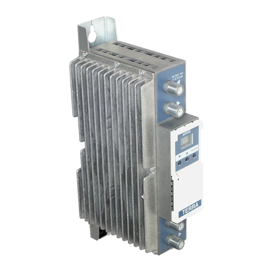
External view
Figure 1. External view and structure diagram
Quattro TV channel amplifier at440
1 - ◄ - RF input, DC output +12 V switchable (F socket)
2 - ►- RF output (input signal loop-through) (F socket)
3 - two digit LED display
4 - +12 V powering input (screw terminal)
5 - ◄ - RF input (output signal loop-through) (F socket)
6 - ► - RF output (F socket)
7 - power distribution bus connector (under the cover)
Advertisement

Related Manuals for Terra at440


Summary of Contents for Terra at440
- Page 1 To enter dC mode, “ENTER” key must be pressed. dC value The at440 is intended to filter and equalize UHF TV channel 21 – 60 (470 – 790 MHz) signals before distribution in MATV (0V/12V) can be set by pressing (▼-minus or ▲- plus) keys.
- Page 2 Equipment intended for indoor usage only. TERRA confirms, that this product is in accordance to following norms of EU: EMC norm EN50083-2, safety norm EN60065, RoHS norm EN50581. TERRA confirms, that this product is in accordance with Custom Union Technical Regulations: “Electromagnetic compatibility of technical Figure 3.
Need help?
Do you have a question about the at440 and is the answer not in the manual?
Questions and answers