Advertisement
Quick Links
Especificaciones tecnicas
Ganacia
FM (88-108 MHz)
VHFIII (174-260 MHz)
UHF (470-862 MHz)
Numero de entradas
Figura de ruido
Nivel salida maxima IMD3=60 dB (DIN45004B)
Control de ganancia
atenuador
interruptor
Perdida de retorno
DC para equipos externos (total)
Alimentación
Consumo*
Rango de temperatura de trabajo
Dimensionses/Peso
* sin carga DC externa;
con carga máxima de DC externa 0.58 A
Diagrama de estructura
Este producto cumple con la Directiva Europea 2002/96/EC. La unidad debe ser reciclado o desechado de
acuerdo con la normativa local y nacional.
Equipo diseñado para uso exclusivo en interior.
TERRA declara que este producto cumple con las siguientes normas de seguridad de la Directiva Europea EMC: EN50083-2,
EN60065 y RoHS EN50581.
TERRA declara que este producto cumple las normativas en conformidad con el Reglamento Técnico de la Unión Aduanera:
"Compatibilidad electromagnética de equipos técnicos" CU TR 020/2011, "Sobre la seguridad de bajo voltaje de los equipos"
CU TR 004/2011.
TERRA declara que este producto es conforme a la norma de seguridad AS/NZS 60065 y las normas EMC de Australia.
Draugystes str. 22, LT-51256 Kaunas, Lithuania, tel.: +370 37 - 31 34 44, fax: +370 37 - 31 35 55
E-mail: sales@terraelectronics.com, http://www.terraelectronics.com
30 dB
30 dB
30 dB
3
VHF < 7 dB; UHF < 5 dB
VHF 116 dBµV; UHF 118 dBµV
0 ÷ -15 dB
0/-10 dB
> 10 dB
12 V
0.1 A max.
12 ± 1 V
0.48 A
÷ +50
0
o
o
C
198x107.5x36 mm/ 0.9 kg
Multichannel headend
Multiband amplifier ma400
Product description
The multiband amplifier ma400 is intended to amplify RF signals in FM, VHFIII and UHF bands. The splitband design
ensures low intermodulation distortion.
Each input has 15 dB fine gain regulator and discrete 0/10 dB gain stage switch.
The amplifier provides +12 V DC power for external equipment through each input connector independently (control by
switches).
The amplifier can be used as stand-alone unit as well as modular system part powered from single power supply through
power input (5) or power distribution bus connector (6).
The amplifier is intended for indoor use only.
Safety instructions
Installation of the amplifier must be done according IEC60728-11 and national safety standards.
The amplifier is powered from power supply unit (PSU) +12 V. This voltage is not dangerous to life.
Output of PSU +12 V must have a short circuit protection.
Any repairs must be done by a qualified personnel.
Do not plug the PSU +12 V into the mains socket until all modules cables have been connected correctly;
The mains socket of PSU +12 V must be easily accessible;
To disconnect the amplifier completely, disconnect the PSU +12 V from the mains.
The amplifier shall not be exposed to dripping or splashing water and no objects filled with liquids, such as vases, shall
be placed on it;
Avoid placing amplifier next to central heating components and in areas of high humidity;
No naked flame sources, such as lighted candles, should be placed on amplifier;
If the amplifier has been kept in cold conditions for a long time, keep it in a warm room no less than 2 hours before
plugging into the mains;
The ventilation should not be impeded by covering the ventilation openings with items, such as newspapers, table-cloths,
curtains;
Mount the amplifier in vertical position;
From top, front and bottom of installed amplifier must be at least 10 cm free space.
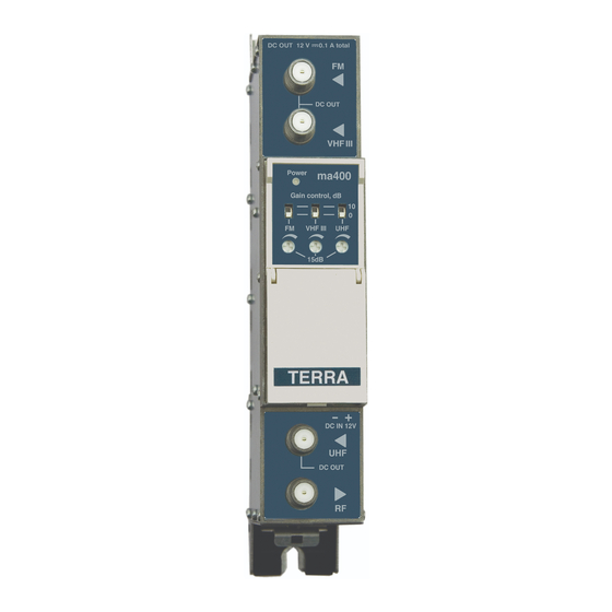
External view
Figure 1. External view of the amplifier
1 - 10 dB gain switches
2 - 15 dB fine gain regulators
3 - DC for external equipment switches
4 - LED indicator of the amplifier's status
5 - +12 V powering input (screw terminal)
6 - powering and power distribution bus connector
7 - ◄ - FM input, DC output +12 V switchable (F socket)
8 - ◄ - VHFIII input, DC output +12 V switchable (F socket)
9 - ◄ - UHF input, DC output +12 V switchable (F socket)
10 - ► - RF output (F socket)
Advertisement

Related Manuals for Terra MA400


Summary of Contents for Terra MA400
- Page 1 Product description UHF (470-862 MHz) 30 dB The multiband amplifier ma400 is intended to amplify RF signals in FM, VHFIII and UHF bands. The splitband design Numero de entradas ensures low intermodulation distortion. Each input has 15 dB fine gain regulator and discrete 0/10 dB gain stage switch.
- Page 2 Montaje en DIN rail Installation instructions Read the safety instruction first. If any of RF connectors are not used, connect 75 Ω isolated load. Operating Turn on the regulators clockwise with supplied plastic screw driver to increase gain for each sub-band (figure 1, pos. 2). The powering circuit has overload and short circuit protection.
- Page 3 Instrucciones de instalacion Mounting on DIN rail En primer lugar, lea las instrucciones de seguridad con atención. Si cualquiera de los conectores RF no se utilizan, conecte una carga aislada de 75 Ω. Funcionamiento Gire los trimmer en el sentido de las agujas del reloj, con el destornillador de plástico suministrado, para aumentar la ganancia para cada sub-banda (figura 1, pos.
- Page 4 10 - ► - salida RF (conector F) TERRA confirms, that this product is in accordance to following norms of EU: EMC norm EN50083-2, safety norm EN60065 and RoHS norm EN50581. TERRA confirms, that this product is in accordance with Custom Union Technical Regulations: “Electromagnetic compatibility of technical equipment“...
Need help?
Do you have a question about the MA400 and is the answer not in the manual?
Questions and answers