Table of Contents
Advertisement
Quick Links
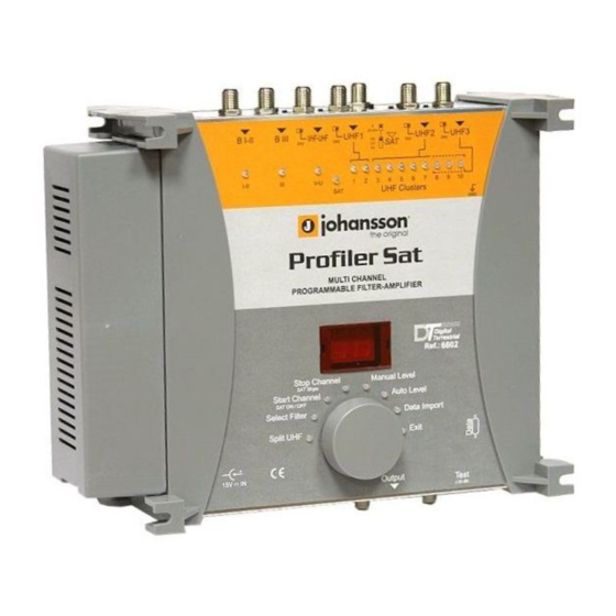
Multi Channel Programmable Filter-Amplifier
Digital
Terrestrial
FEATURES
- Designed for both digital and analogue Satellite and Terrestrial channels,
- 1 SAT input + 6 Terrestrial inputs :
B I-II / B III / VHF-UHF and 3 UHF inputs splitted over 10 UHF programmable clusters,
- Each cluster can have 1 to 7 channels bandwidth,
- Easy programming by using one rotary / push button viewed on 2 digits display and LEDs for each cluster
and each input,
- 'COPY' function in order to transfer all settlements from one unit to another reducing time of installation,
- High selectivity filters,
- Low noise figure amplifiers,
- High gain and output power,
- VHF-UHF-SAT split band amplifiers with interstage attenuators for VHF-UHF,
- Automatic leveling of signal or manual by attenuator with 1 dB step for accurate equalization
- Selectable remote power on VHF-UHF and UHF inputs,
- 0 - 13 - 18V / 0 - 22 kHz remote power for LNB,
- -30 dB Test output.
R
User Manual
0
22 kHz
B I-II
B III
VHF-UHF
UHF1
24V
24V
18V
13V
0V
I-II
III
V-U
1
2
3
SAT
UHF Clusters
MULTI CHANNEL
PROGRAMMABLE FILTER-AMPLIFIER
Stop Channel
Manual Level
SAT Slope
Start Channel
SAT ON / OFF
Select Filter
Split UHF
+
15V
IN
Output
Ref. : 6602
UHF2
UHF3
24V
24V
SAT
4
5
6
7
8
9
10
GND
R
Digital
Terrestrial
Ref.: 6602
Auto Level
Data Import
Exit
Test
(-30 dB)
Advertisement
Table of Contents

Related Manuals for Johansson Profiler SAT


Summary of Contents for Johansson Profiler SAT
- Page 1 Ref. : 6602 Multi Channel Programmable Filter-Amplifier User Manual Digital 22 kHz B I-II B III VHF-UHF UHF1 UHF2 UHF3 Terrestrial I-II UHF Clusters MULTI CHANNEL PROGRAMMABLE FILTER-AMPLIFIER Digital Terrestrial Ref.: 6602 Stop Channel Manual Level SAT Slope Start Channel Auto Level SAT ON / OFF Select Filter...
-
Page 3: Safety Instructions
SAFETY INSTRUCTIONS Read carefully these instructions before connecting the unit. The operating voltage is indicated on the adapter. To prevent fire, short circuit, shock hazard: Do not expose the unit to rain or moisture. Install the unit in a dry location without infiltration or condensation of water. Do not expose it to dripping or splashing. - Page 4 DESCRIPTION 0 - 13V - 18V 0 - 22 kHz BI-FM BIII / DAB UHF-VHF UHF1 UHF2 UHF3 LEDs for Inputs and Clusters Grounding 2 Digit Display Mains 230V~ DSUB9 Connector Rotary / Push Button Mode / Function LEDs Output Test Output...
-
Page 5: Operation
OPERATION All parameters are set with the rotary push button. Each function and parameters are shown on 2 digits display and different LEDs . Programming - Make all the necessary connections and connect amplifier to mains. The software version is displayed, followed by a dot. - Page 6 CLUSTER PROGRAMMING Setting clusters / UHF input - The amplifier has 3 UHF inputs which are splitted over 10 clusters. There are three possible configurations : Input UHF1 UHF2 UHF3 UHF1 clusters are indicated by the YELLOW LEDs n° 1 and 2. Number of UHF2 clusters are indicated by the RED LEDs n°...
- Page 7 Setting channels / cluster Each cluster has a bandwidth which can be programmed from 1 to 7 channels : To set the channel(s) per cluster : In the following example cluster 1 is set for channel 22 to channel 26. - Turn the button to select the Select Filter mode.
- Page 8 Notes : - Single channel mode : When the Start Channel is selected, the Stop Channel is automatically set at the same value. Start Channel - Park function : to switch off the cluster, select Start Channel and set 00. The Stop Channel goes automaticaly to 00.
- Page 9 To check the channel settings of each cluster : - Turn the rotary button to select Select Filter. Select Filter The LED is GREEN. - Push the rotary button to enter the selected mode. Select Filter The LED is now RED colored. - Turn the button to choose the cluster to be checked.
-
Page 10: Level Adjustment
LEVEL ADJUSTMENT Levels are manually set for each input and / or automatically for the UHF clusters. Automatic level setting The levels of BI-II / BIII / VHF-UHF / SAT are not processed in the Auto Level function. - Turn the button to choose the Auto Level. Auto level The LED is GREEN. - Page 11 After automatic level setting procedure, the general level of the UHF signals (clusters and the UHF part of the VHF-UHF input) can be adjusted from +10 dB to -9 dB in steps of 1 dB. General UHF level setting - Select all the clusters and VHF-UHF. - Turn the button to choose the Select Filter mode.
- Page 12 Manually level setting To set manually the level. - Select the desired input or cluster. Example : setting the level of BI-II - Turn the button to choose the Select Filter mode. Select Filter The LED is green. - Push the rotary button to enter the selected mode. Select Filter The LED is now RED colored.
-
Page 13: Sat Operation
SAT OPERATION Select the SAT input. - Turn the button to choose the Select Filter mode. Select Filter The LED is green. - Push the rotary button to enter the selected mode. Select Filter The LED is now RED colored. - Turn the button to select SAT. - Page 14 To set the Gain. - Turn the button to select the Manual Level mode. Manual Level The LED is green. - Push the rotary button to enter the selected mode. Manual Level The LED is now RED colored. - Turn the button to set the level, variable from 20 dB to 0 dB. - Push the button to confirm.
- Page 15 To switch OFF the SAT amplifier - Turn the button to choose the Select Filter mode. Select Filter The LED is green. - Push the rotary button to enter the selected mode. Select Filter The LED is now RED colored. - Turn the button to select SAT.
-
Page 16: Copy Function
COPY FUNCTION This function allows to transmit all settings from one unit to another unit. All actions have to be done on the SLAVE unit. The MASTER unit remains in Stand-by. B I-II B III VHF-UHF UHF1 22 kHz UHF2 UHF3 B I-II B III... -
Page 17: General Reset
GENERAL RESET This function can reset all clusters and attenuators to zero. - Disconnect the mains power. 22 kHz B I-II B III VHF-UHF UHF1 UHF2 UHF3 I-II UHF Clusters M ULTI CHANNEL PROGRAM M ABLE FILTER-AM PLIFIER Digital Terrestrial Ref.: 6602 Stop Channel Manual Level... -
Page 18: Block Diagram
BLOCK DIAGRAM... -
Page 19: Technical Specifications
TECHNICAL SPECIFICATIONS BI-FM BIII VHF-UHF UHF 1 UHF 2 UHF 3 47-108 174-240 47-240 + 470-862 470-862 470-862 470-862 950-2300 8-56 (1 to 7 channels / cluster) " +10 dB to -9 dB " &' " ( &' VHF:118 / UHF:123 "... - Page 20 Specifications are subject to change without notice. 05/05 UNITRON n.v. Frankrijklaan 27 TEL +32 5733 3363 FAX +32 5733 4524 B-8970 Poperinge Belgium www.johansson.be e-mail: sales@johansson.be...
Need help?
Do you have a question about the Profiler SAT and is the answer not in the manual?
Questions and answers