Table of Contents
Advertisement
Quick Links
Advertisement
Table of Contents

Related Manuals for Johansson Super Profiler 6630


Summary of Contents for Johansson Super Profiler 6630
- Page 1 Super Profiler installation guide 6630...
- Page 2 Unitron can not be held liable for any damages resulting from the use of this product. Specifications are subject to change without notice. 09/11 © Unitron - Frankrijklaan 27 - B-8970 Poperinge - Belgium T +32 57 33 33 63 F +32 57 33 45 24 email sales@johansson.be www.johansson.be - www.unitrongroup.com...
-
Page 3: Table Of Contents
CONTENTS 1 INTRODUCTION the Profiler range ........................package contents ........................safety instructions ........................accessories ..........................2 INSTALLATION OF THE HARDWARE module overview ........................3 CONFIGURATION OF THE DEVICE control unit ..........................PC control ..........................4 BLOCK DIAGRAM ....................... 5 TECHNICAL SPECIFATIONS ................... -
Page 4: Introduction
1 INTRODUCTION THE PROFILER RANGE Profiler Plus 10 clusters » REF. 6620 10 highly selective filters (1-7 channels) 4 UHF inputs FM/VHF/AUX input high output power: >120 dBµV 2 programmable outputs Profiler Plus SAT 10 clusters » REF. 6621 10 highly selective filters (1-7 channels) 4 UHF inputs SAT input FM/VHF/AUX input... - Page 5 Profiler Plus 12 clusters » REF. 6622 12 highly selective filters (1-7 channels) 4 UHF inputs FM/VHF/AUX input high output power: >120 dBµV 2 programmable outputs Profiler Plus SAT 12 clusters » REF. 6623 12 highly selective filters (1-7 channels) 4 UHF inputs SAT input FM/VHF/AUX input...
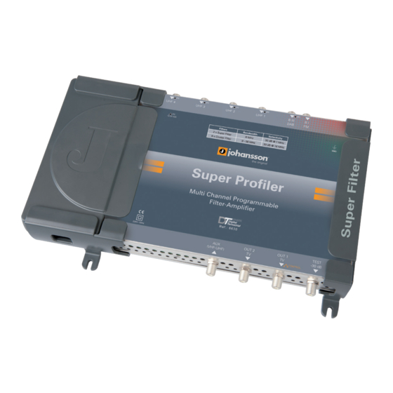
- Page 6 Super Profiler » REF. 6630 2 super selective filters: 30 dB @ 1 MHz 8 highly selective filters (1-7 channels) frequency conversion functionality 4 UHF inputs FM/VHF/AUX input high output power: >120 dBµV 2 programmable outputs Super Profiler SAT » REF.
-
Page 7: Package Contents
PACKAGE CONTENTS Be sure all items listed below are included: Profiler Plus module (ref. 6630) power cord user manual... -
Page 8: Safety Instructions
SAFETY INSTRUCTIONS Read these instructions carefully before connecting the unit To prevent fire, short circuit or shock hazard: Do not expose the unit to rain or moisture. Install the unit in a dry location without infiltration or condensation of water. Do not expose it to dripping or splashing. - Page 9 To avoid any risk of electrical shocks: Connect apparatus only to socket with protective earth connection. The mains plug shall remain readily operable. Pull out power plug to make the different connections of cables. To avoid electrical shock, do not open the housing of adapter. Maintenance Only use a dry soft cloth to clean the cabinet.
-
Page 10: Accessories
ACCESSORIES Control Unit » REF. 6565 control different Johansson products big OLED display for easy reading operating voltage: 5-24V power through coax cable or with delivered adapter Ethernet-To-Coax » REF. 6564 control profiler products by PC (this unit is the... -
Page 11: Installation Of The Hardware
2 INSTALLATION OF THE HARDWARE MODULE OVERVIEW 60 mm 220 mm 325 mm hole for mounting screw SAT input (6621 / 6623 / 6631 only) BI-FM input BIII-DAB input UHF input 1 UHF input 2 UHF input 3 UHF input 4 detachable power supply... - Page 12 power cord connection hole for mounting screw AUX (VHF-UHF) output TV output 2 TV output 1 & control unit input test output (-30 dB) detachable power supply...
-
Page 13: Configuration Of The Device
3 CONFIGURATION OF THE DEVICE There are two ways of configuring the Profiler. In both cases, you need an optional ac- cessory. The operation of these accessories is described in the respective manuals. CONTROL UNIT The device can be controlled by means of a separate control unit (ref. 6565), which is connected to the test output port of the unit. - Page 14 The operation of the control unit (ref. 6565) is explained in the manual of the 6565. The menu structure of the profiler is shown in the following picture: PRESS 3 S PRESS 3 SECO...
- Page 15 SECONDS ONDS...
-
Page 16: Pc Control
PC CONTROL The device can be controlled by PC with our advanced UUI (Universal User Interface). You need an Ethernet to Coax adapter (ref. 6564) and the UUI software. The UUI gives access to all possible functionalities of the hardware and allows an easy and conveni- ent way of configuring the device. -
Page 17: Block Diagram
4 BLOCK DIAGRAM... -
Page 18: Technical Specifications
5 TECHNICAL SPECIFICATIONS 6630 BIII/ BI-FM UHF1 UHF2 UHF3 UHF4 SUPER PROFILER 47-68 174-240 47-862 470-862 470-862 470-862 470-862 FREQUENCY RANGE (MHz) 88-108 8-56 (1 to 7 channels) FILTER BANDWIDTH (MHz) GAIN* (dB) ATTENUATOR (dB) SLOPE ADJUSTMENT (dB) GENERAL UHF LEVEL +10 to -10 ADJUSTMENT (dB) NOISE FIGURE (dB) -
Page 19: Conditions Of Warranty
6 CONDITIONS OF WARRANTY PERIOD OF WARRANTY Unitron N.V. warrants the product as being free from defects in material and workmanship for a period of 24 months starting from the date of production indicated on it. See note below. If during this period of warranty the product proves defective, under normal use, due to defective materials or workmanship, Unitron N.V, at its sole option, will repair or replace the product. -
Page 20: Frequency Table
7 UHF FREQUENCY TABLE TV band Channel Frequency MHz 470-478 478-486 486-494 494-502 502-510 510-518 518-526 526-534 534-542 542-550 550-558 558-566 566-574 574-582 582-590 590-598 598-606 606-614 614-622 622-630 630-638 638-646 646-654 654-662 662-670 670-678 678-686 686-694 694-702 702-710 710-718 718-726 726-734 734-742... -
Page 21: Power Conversion Table
8 POWER CONVERSION TABLE µV 75 Ω dBµV mV 75 Ω dBµV V 75 Ω dBµV -109 -105.5 63.5 -45.5 123.5 +14.5 -103 -101 -99.5 69.5 -39.5 129.5 +20.5 15.5 -93.5 75.5 -33.5 135.5 +26.5 23.5 -85.5 83.5 -25.5 29.5 -79.5 89.5 -19.5... - Page 24 UNITRON NV Frankrijklaan 27 B-8970 Poperinge Belgium T +32 57 33 33 63 F +32 57 33 45 24 sales@johansson.be www.johansson.be...
Need help?
Do you have a question about the Super Profiler 6630 and is the answer not in the manual?
Questions and answers